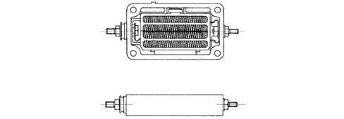
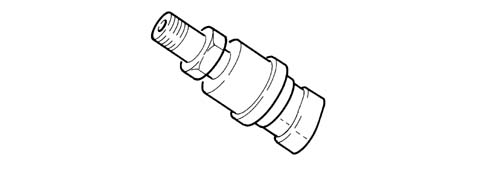
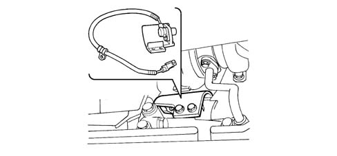
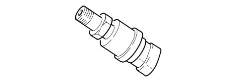
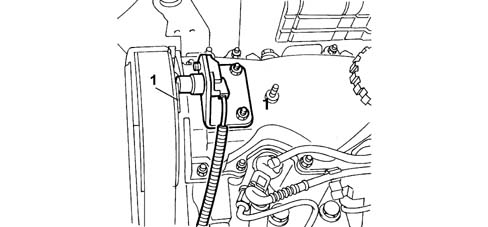
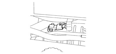
The heat flange ensures engine start-up even at low temperatures. The device is fitted on the intake manifold intake and consists of a heating coil that is controlled by relay and a signal from the injection control unit.
Engines: 2.3 JTD 16V
Fiat Ducato commercial vehicles are equipped with a 2300 cc 4 cylinder in-line turbodiesel engine with Bosch electronic injection, four valves per cylinder and two overhead camshafts. They are air turbocharged by means of a turbocharger and intercooler.
Engines: 2.8 JTD 8V
Cold outside air passes over the heating coils to heat the air so that it reaches the engine combustion chamber at a high enough temperature for engine start-up to take place.The device is activated and deactivated by a relay controlled by the injection unit in accordance with internal maps. This device is fitted as an alternative to a thermal starter.
Engines: 2.3 JTD 16V
The fuel system ensures the engine operates correctly and may be schematically broken down into the following circuits:
fuel supply circuit with Common Rail injection;
air supply circuit;
exhaust circuit;
crankcase oil vapour recirculation circuit;
exhaust gas recirculation circuit (EGR).
Engines: 2.8 JTD 8V
Engines: 2.3 JTD 16V
Operation of the various circuits that make up the fuel system is optimised by an electronic control system managed by a special control unit.The main feature of the fuel system is Common Rail fuel injection.The Common Rail system is a high pressure electronic injection circuit for fast, direct injection diesel engines.The main features of the Common Rail system are as follows:
availability of high pressure (up to 1600 bars);
possibility of modulating these pressures (from a minimum of 150 bars to a maximum of 1600 bars) independently of engine rotation speed (rpm) and load;
ability to work at high engine rpms (up to 5000 rpm);
injection control precision (injection advance and duration);
reduction in fuel consumption;
reduction in emissions.
FUEL SYSTEM MANAGEMENT STRATEGIES
The control unit memory contains a management programme (software) that includes a set of strategies, each of which manages a specific system control function.Each strategy uses information provided by the various sensors (input) to process a set of parameters that are based on data maps stored in special control unit memory areas. The strategy then controls system actuators (output) that allow the engine to operate.The main purpose of the management strategies is to calculate the exact amount of fuel to be injected into the cylinders. The associated timing (injection advance) and precision are set to ensure the best possible engine performance in terms of power, fuel consumption, fume emissions and vehicle handling.The main system management strategies are essentially as follows:
control of injected fuel quantity;
cylinder balance check when idling;
injetion advance control;
control of anti-judder function;
injection pressure control;
turbocharging control;
engine coolant temperature control;
fuel pre-feed pump control;
exhaust fume control;
injection control during over-run (cut-off);
maximum speed limit control;
idle speed check
exhaust gas recirculation control (E.G.R.);
maximum torque limit control;
climate control system activation control;
self-diagnosis;
engine immobiliser function control.
HIGH PRESSURE ELECTRONIC FUEL INJECTION SYSTEM (COMMON RAIL)
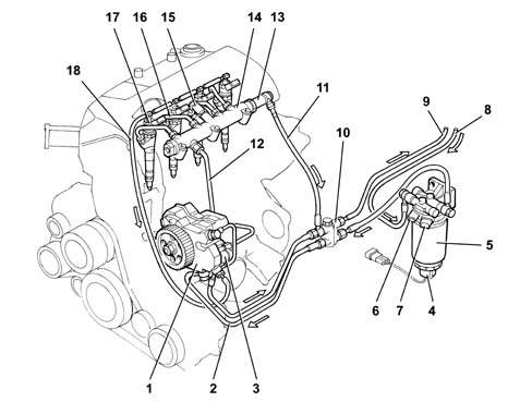
Very high injection pressures are required to eliminate particulate emissions. The Common Rail system allows fuel to be injected at pressures of up to 1600 bars. The injection precision achieved by electronic system management optimises engine operation to limit emissions and fuel consumption. Glow plugs are used for preheating to facilitate cold starts.Schematic view of the Common Rail system
1 - High pressure pump
2 - Fuel inlet pipe from filter
3 - Pressure regulator
4 - Sensor to detect presence of water in filter
5 - Fuel filter with water separator
6 - Fuel temperature sensor
7 - Fuel preheating
8 - Pipe carrying fuel to filter
9 - Fuel return pipe to tank
10 - Four-way adaptor
11 - Low pressure return pipe from Common Rail to four-way adaptor
12 - High pressure delivery pipe to Common Rail
13 - Pressure relief valve
14 - Common Rail
15 - Pressure sensor
16 - High pressure pipe between Rail and injectors
17 - Injectors
18 - Return pipe from injectors
In this Common Rail injection system with a CP3 pump, the pressure regulator located upstream of the high pressure pump modulates the fuel flow to the level required by the low pressure system. The high pressure pump then supplies the Rail correctly.Because this solution only pressurises the required amount of fuel, energy efficiency is improved and system fuel heating is limited. The limit valve fitted to the high pressure pump maintains a constant pressure of 5 bars at the pressure regulator input regardless of the efficiency of the fuel filter and upstream system. The limit valve cuts in to increase fuel flow in the high pressure pump cooling circuit.Pump CP3 maintains fuel continuously at high pressure regardless of phase and cylinder receiving the injection. Pressure thus accumlates in a duct shared by all injectors.Fuel at an injection pressure calculated by the ECU is therefore always available at the injector input.When the solenoid of one injector is excited by the electronic control unit, fuel taken directly from the Rail is injected into the relevant cylinder.The hydraulic system comprises one low pressure circuit and one high pressure circuit. The high pressure circuit consists of the following pipes:
pipe connecting the high pressure pump outlet to the Rail;
Common Rail;
pipes that supply the injectors from the Rail.
The low pressure circuit consists of the following pipes:
fuel inlet pipe from the tank to the prefilter;
pipes supplying the mechanical supply pump and the prefilter;
pipes supplying the high pressure pump via the fuel filter.
The fuel system is completed by the fuel outlet circuit from the Rail and injectors.For safety reasons due to the high pressures in this hydraulic system it is absolutely necessary to:
avoid tightening the high pressure pipe fittings to an approximate torque;
avoid disconnecting the high pressure pipes with the engine running (do NOT attempt to bleed because this is absolutely pointless and dangerous!)
Because the low pressure circuit must also be undamaged for the system to operate efficiently, avoid handling or modification and take action immediately to rectify leaks.
Control of amount of fuel injected
The control unit controls the fuel pressure regulator and injectors on the basis of signals received from the accelerator pedal, debimeter or air pressure sensor in the intake manifold and the engine rpm sensor.Injection timing and sequence are determined upon engine start-up using signals from the engine rpm sensor and timing sensor (synchronisation stage). Injection timing is then implemented using the engine rpm sensor signal alone and considering the 1 - 3 - 4 - 2 injection sequence of the 2300 JTD engine.The control unit inhibits injection in the following cases:
Fuel pressure value greater than 1700 bar;
Fuel pressure value lower than 100 bar;
engine speed greater than 5000 rpm.
When the engine is warm, maximum injection duration (injector opening time) is 1500 s. The duration may extend to 4500 s during start-up.
Injection advance control
The electronic control unit determines injection advance mainly on the basis of the amount of fuel to be injected and engine speed.Injection advance is then corrected on the basis of engine coolant temperature in order to compensate for the increase in ignition delay due to low temperatures present in the combustion chambers during warm-up.
Injection pressure control
This control is important because injection pressure influences the following parameters:
amount of fuel taken into the cylinders for the same injection time duration;
nebulisation of fuel injected;
jet penetration;
delay between electric injector control and the effective start of fuel injection;
duration of fuel injection in the combustion chamber.
The above parameters influence engine behaviour crucially, particularly in terms of power supplied, exhaust emissions, noise and car handling.The engine control unit controls the high pressure pump intake pressure regulator as required on the basis of engine load and engine speed to ensure optimal line pressure at all times.When the engine is cold, injection pressure is corrected on the basis of coolant temperature to meet engine requirements at different service temperatures.Fuel pressure is modulated according to instantaneous engine service conditions (speed, load etc.).The lower pressure is compensated for by longer injection times and viceversa, taking into account required loads at all times.Up to 2800 rpm, a preinjection is also carried out to reduce the noise typical of direct injection.Pre-injection advance angles, distance between pre-injection and main injection and main injection advance angles vary according to instantaneous engine operating conditions.
Control of electric fuel pre-supply pump
The auxiliary fuel pump submerged in the tank is supplied by the engine control unit via a relay when the ignition key is in MAR position.The pump supply is inhibited under the following circumstances:
after the ignition key has been in MAR position for 10 seconds and the engine is not operating;
if the inertia switch has gone off.
Injection control during over-run (cut-off)
The fuel cut-off strategy is implemented when the engine control unit receives information from the potentiometer, which sends a signal to indicate that the accelerator pedal has been released by the user.Under these conditions, the control unit cuts off the power supply to the injectors and reactivates it before reaching idle speed. It also controls the fuel pressure regulator.
Idle speed control
The injection control unit controls the pressure regulator and alters injector opening times on the basis of signals from the engine rpm sensor and coolant temperature sensor to keep idle speed stable. Under certain conditions, the control unit takes battery voltage into account to control idle speed.
Maximum speed limit control
The engine control unit intervenes in two ways to limit maximum speed on the basis of rpm:
as maximum speed approaches (4600 rpm), the amount of fuel injected falls and line pressure is reduced;
injector operation is inhibited at speeds over 5000 rpm.
Maximum torque limit control
The injection control unit calculates limit torque and maximum permitted fume index parameters according to rpm. The calculations are based on predefined maps stored in its memory. The control unit corrects the above parameters using engine coolant and vehicle speed data and uses the resulting values to modulate the amount of fuel to be injected by adjusting the pressure regulator and injectors.
Control of fuel temperature
The injection control unit is constantly informed of fuel temperature by means of a specific sensor in the fuel filter.If fuel temperature exceeds a set level ( 80°C), the engine control unit gradually reduces maximum power to 90°C to achieve a minimum level of 60% of nominal power.
Engine coolant temperature control
The injection control unit is constantly informed of coolant temperature by means of a sensor on the thermostat.If engine coolant temperature exceeds certain levels, the control unit takes the following actions:
reduces the amount of fuel injected by adjusting the pressure regulator and injectors (power reduction from a level of 106°C).
controls the engine cooling fan (activation/deactivation temperature at 95 / 91°C for the first speed and 99 / 95°C for the second speed).
When the ignition key is turned to STOP (if the temperature exceeds the cooling system activation threshold), the fan stays on for a maximum time of 20 seconds to take the temperature below the cooling system activation threshold.When the ignition key is turned to the ON position. (coolant temperature exceeds the cooling system activation threshold), the fans do not activate until engine rpm exceeds 770 rpm. (engine speed when warm is 800 rpm).
Exhaust fume control
The injection control unit limits any exhaust fumes that could occur during strong acceleration.To meet this requirement, the control unit processes signals from the accelerator pedal potentiometer, engine rpm sensor and intake air quantity sensor (debimeter or pressure/temperature sensor); the inejction control unit controls the fuel pressure regulator and injectors to modulate the amount of fuel to be injected into the combustion chamber and reduce exhaust fume levels.
Exhaust gas recirculation control
The injection control unit, on the basis of signals supplied: by sensors measuring engine rpm, intake air quantity (debimeter), engine coolant temperature and accelerator pedal position, controls EGR valve activation to achieve partial exhaust gas recirculation only under certain engine service conditions.
Control of air conditioning system activation
The engine control unit manages the vehicle air conditioning system compressor electromagnetic coupling by pursuing a strategy that prevents engine performance being penalised while the air conditioner is being used.When the compressor is activated, the engine control unit increases the amount of fuel at idle speed to adjust the engine to the higher power requirement and cut off power supply to the compressor under conditions of:
excessive coolant temperature (threshold of 105°C for deactivation and 100°C for reactivation).
Engine immobiliser function control
The system is equipped with an engine immobiliser. This function is executed by a control unit (Fiat CODE) able to communicate with the engine control unit and an electronic key with a transmitter that sends out a recognition code. Whenever the key is turned OFF, the Fiat CODE system fully deactivates the engine control unit.When the key is turned ON, the following operations take place in sequence:
the engine control unit (with the secret code in its memory) sends the Fiat CODE control unit a secret code request that deactivates the function lock;
the Fiat CODE control unit responds by sending back the secret code only once it has received, in turn, a recognition code sent by the ignition key.
secret code recognition allows engine control unit lock deactivation and resumption of normal operation.
Self-diagnosis
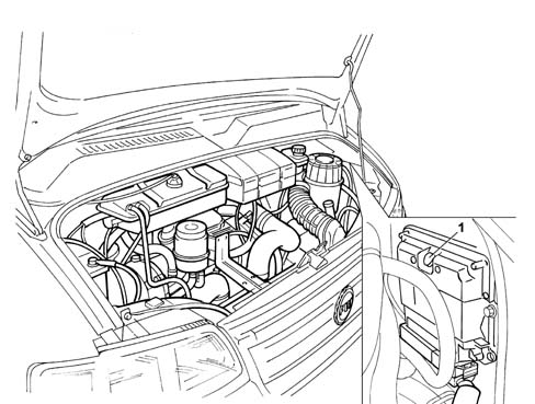
Full injection system electronic diagnosis is carried out by connecting an appropriate tester (EXAMINER or SDC station) to the tester input located in the engine bay.The system also comes with a self-diagnostic function that detects, stores and indicates faults.If a fault is detected in a sensor or actuator, signal reconstruction strategies (recovery) are immediately activated to ensure the engine operates at an acceptable level without impairing service. The vehicle can therefore be driven to a service outlet for the necessary repairs.
BOSCH EDC MS6-3 ENGINE CONTROL UNIT
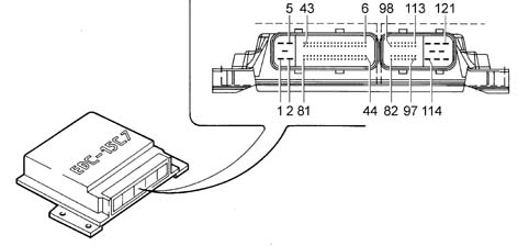
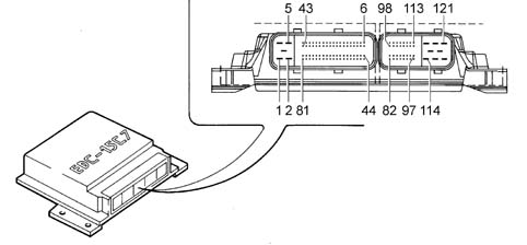
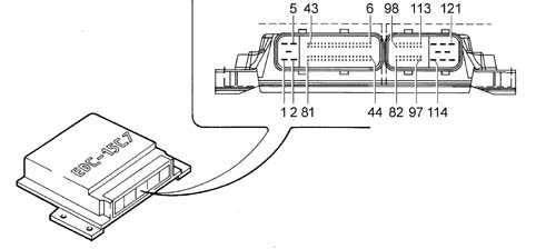
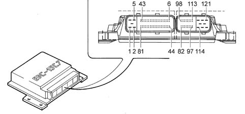
The EDC MS6-3 processes signals from the sensors by applying software algorithms and controls actuators (particularly the injectors and pressure regulator) to achieve the most effective possible engine operation.The control unit is flash E.P.R.O.M. type and can be reprogrammed externally without the need to adjust the hardware.The engine control unit contains a built-in atmospheric pressure sensor and is connected to the wiring by means of 2 connectors that provide a total of 121 pins.
Identification of EDC MS6-3 engine control unit connections
Currently available versions are:
2.3 JTD engine with EGR;
2.3 JTD engine without EGR;
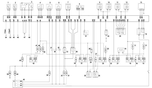
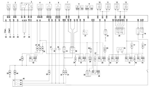
Version with EGR
Diagram showing injection system with EGR
1 - Fuel temperature sensor.
2 - Engine coolant temperature sensor.
3 - Air flow meter (debimeter).
4 - Fuel pressure sensor.
5 - Engine rpm sensor.
6 - Timing sensor.
7 - Fuel pressure regulator.
8 - Fuel filter heater relay.
9 - Cylinder no. 1 injector.
10 - Cylinder no. 2 injector.
11 - Cylinder no. 3 injector.
12 - Cylinder no. 4 injector.
13 - Glow plug control unit.
14 - 4 stage pressure switch.
15 - Engine cooling relay (high speed)
16 - 40 A fuse.
17 - Engine cooling fan.
18 - Engine cooling relay (high speed)
19 - Resistor.
20 - Potentiometer on accelerator pedal.
21 - Engine cooling relay (low speed)
22 - 40 A fuse.
23 - Compressor.
24 - Sensor on clutch pedal.
25 - Compressor control relay.
26 - Throttle solenoid.
27 - 7.5 A fuse.
28 - Inertia switch
29 - Electric pump submerged in tank.
30 - EGR solenoid.
31 - Pulse generator.
32 - Relay controlling electric pump submerged in tank.
33 - Vehicle brake light control.
34 - 15 A fuse.
35 - 7.5 A fuse.
36 - Preheating warning light.
37 - Injection system failure warning light.
38 - 7.5 A fuse.
39 - 15 A fuse.
40 - 10 A fuse.
41 - 20 A fuse.
42 - Main relay.
43 - 7.5 A fuse.
44 - 20 A fuse.
45 - Ignition switch.
46 - Tester input.
47 - Chassis earth.
48 - Fiat CODE control unit.
49 - Signal for rev counter on instrument panel.
50 - Cruise control.
51 - 7.5 A fuse.
52 - Cruise Control activation warning light.
53 - 150 A fuse.
54 - C-Can L network.
55 - C-Can H network.
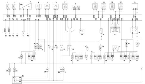
Version without EGR
Diagram showing injection system without EGR
1 - Fuel temperature sensor.
2 - Engine coolant temperature sensor.
3 - Air pressure - temperature sensor in intake manifold.
4 - Fuel pressure sensor.
5 - Engine rpm sensor.
6 - Timing sensor.
7 - Fuel pressure regulator.
8 - Fuel filter heater relay.
9 - Cylinder no. 1 injector.
10 - Cylinder no. 2 injector.
11 - Cylinder no. 3 injector.
12 - Cylinder no. 4 injector.
13 - Glow plug control unit.
14 - 4 stage pressure switch.
15 - Engine cooling relay (high speed)
16 - 40 A fuse.
17 - Engine cooling fan.
18 - Engine cooling relay (high speed)
19 - Resistor
20 - Potentiometer on accelerator pedal.
21 - Engine cooling relay (low speed)
22 - 40 A fuse.
23 - Compressor.
24 - Sensor on clutch pedal.
25 - Compressor control relay.
26 - 150 A fuse.
27 - 7.5 A fuse.
28 - Inertia switch.
29 - Electric pump submerged in tank.
30 - Cruise Control activation warning light.
31 - Pulse generator.
32 - Relay controlling electric pump submerged in tank.
33 - Vehicle brake light control.
34 - 15 A fuse.
35 - 7.5 A fuse.
36 - Preheating warning light.
37 - Injection system failure warning light.
38 - 7.5 A fuse.
39 - 15 A fuse.
40 - 10 A fuse.
41 - 20 A fuse.
42 - Main relay.
43 - 7.5 A fuse.
44 - 20 A fuse.
45 - Ignition switch.
46 - Tester input.
47 - Chassis earth.
48 - Fiat CODE control unit.
49 - Signal for rev counter on instrument panel.
50 - Cruise control
51 - 7.5 A fuse.
52 - C-Can L network.
53 - C-Can H network.
Input/output exchanged between engine control unit and sensors/actuators
The input/output signals exchanged between the engine control unit and sensors/actuators are as follows:input signals:
EDC switch on clutch
speed limit regulation switch
low fuel pressure indication switch
engine coolant temperature sensor
engine oil temperature indicator switch
switch for fuel heater activation
rpm sensor on camshaft
switch for EDC function control
brake pedal pressed signal switch
accelerator pedal potentiometer
pressure regulation sensor
pressure and environmental air temperature sensor for EDC
output signals:
glow plug
brake light activation relay
glow plug activation relay
fuel pump activation relay
EDC relay
EDC failure indication led
preheating indication led on
Instrument panel
pressure regulation solenoid
EGR device control solenoid
electronic injection solenoid
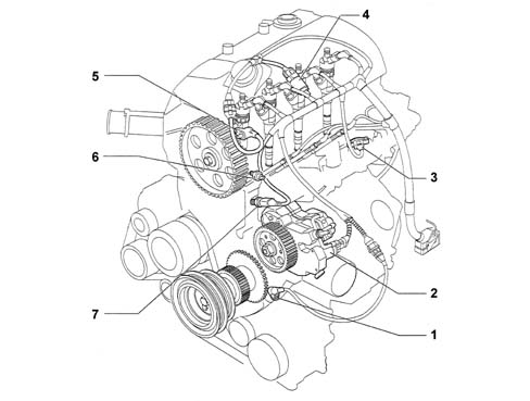
Arrangement of sensors on engine
The following figure shows the arrangement of the sensors on the engine
1 - Engine rpm sensor.
2 - Pressure regulator
3 - Air flow sensor
4 - Rail pressure sensor
5 - Timing sensor
6 - Coolant temperature sensor (indicator on instrument panel)
7 - Coolant temperature sensor (signal to control unit)
Engine rpm sensor
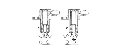
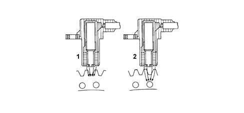
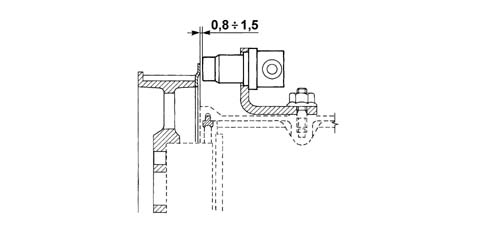
This inductive sensor is located on the engine near the flywheel. The sensor generates signals produced by magnetic flow lines that close through holes in the flywheel. The number of holes is 58.The electronic control unit uses the signal to detect engine rotation speed and angular position and to govern the electronic rev counter.
Operation
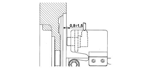
The changeover from full to empty determined by the presence or absence of a hole brings about a magnetic flux change sufficient to generate an induced alternating voltage proportional to the number of holes on the flywheel phonic wheel.Rpm sensor peak output voltage depends, all else being equal, on the distance between the sensor and the phonic wheel holes.To obtain correct signals, the specified distance between phonic wheel and sensor (gap) must be between 0.8 - 1.5 mm.This distance is not adjustable. If the gap is found to be outside the tolerance limits, check the condition of the sensor and phonic wheel.
1 - Maximum magnetic flux
2 - Minimum magnetic flux
Engine coolant temperature sensor
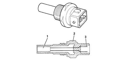
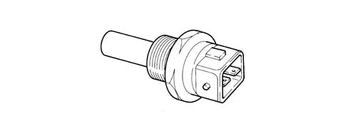
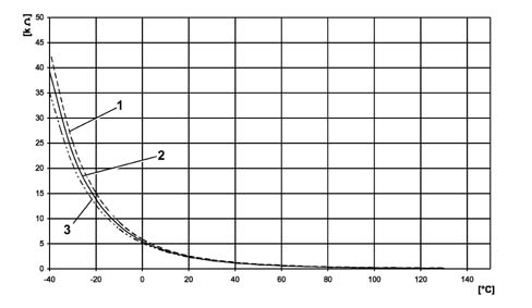
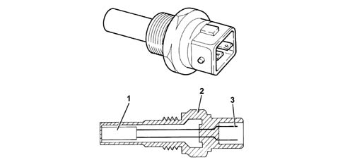
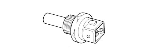
The sensor is installed on the thermostat and detects engine coolant temperature by means of an NTC thermistor with a negative resistance coefficient.The sensor is designed using semiconductor technology. In other words, the resistance level drops if sensor element temperature increases with increasing coolant temperature.Because the resistance does not change in linear fashion as temperature increases, it is relatively higher at low temperatures than at high temperatures.
1 - N.T.C. resistance
2 - Resistor case.
3 - Electrical connector.
Fuel temperature sensor
Fuel temperature sensor (1) incorporated in the fuel filter detects fuel temperature and sends it to the electronic control unit. When fuel temperature is excessive (outdoor environmental temperature condition, engine under full load and tank on reserve), effective high pressure pump lubrication can no longer be guaranteed. The control unit determines fuel density and volume on the basis of input values and corrects output to limit engine performance.
Fuel pressure sensor
The sensor is installed in the middle of the fuel delivery manifold (rail) and is responsible for sending the engine control unit a return signal (feedback) to:
modulate injection pressure;
regulate fuel injection duration.
Timing sensor
This Hall-effect sensor is installed on the cylinder head, where it faces the camshaft pulley.A sector on the pulley allows the timing sensor to detect engine timing position and notify the engine control unit.The injection control unit uses the timing sensor signal to identify T.D.C. at the end of compression.
1 - Timing sensor
Operation
A current-carrying semiconductor layer immersed in a normal magnetic field (force lines at right angles to current direction) generates a potential difference known as a Hall voltage at its terminals.If current intensity remains constant, the generated voltage depends on magnetic field intensity alone. Periodic changes in magnetic field intensity are sufficient to generate a modulated electrical signal with frequency proportional to the speed of magnetic field change.This change is achieved by making a magnetic ring (internal part of pulley) with an opening pass the sensor.As it moves, the metal part of the ring covers the sensor to block the magnetic field and thus generate a low ouput signal. Conversely, the sensor generates a high signal when the opening is over the sensor and a magnetic field is present.This signal, combined with the rpm and T.D.C. signals, allows the injection control unit to identify piston position and determine the injection point.To obtain correct signals, the specified distance between camshaft pulley and sensor (gap) must be between 0.8 - 1.5 mm.This distance is not adjustable. If the gap is found to be outside the tolerance limits, check the condition of the sensor and camshaft pulley.
Air flow meter
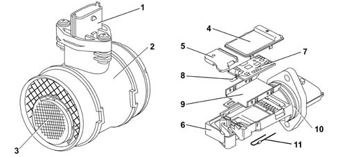
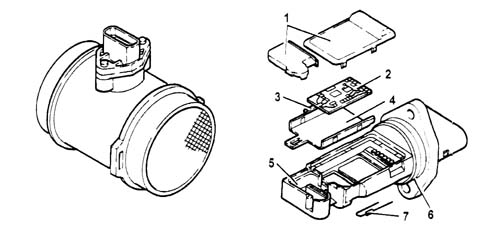
The debimeter is located on the air intake sleeve and is hot film type.The debimeter contains an integral intake air temperature sensor. The debimeter is used in the version with EGR.
Operation
The principle of operation is based on a heated membrane positioned within a measurement channel that carries air into the engine.The hot film membrane is maintained at constant temperature (about 120°C higher than the incoming air temperature) by the heating coil.The air mass that flows through the measurement channel tends to remove heat from the membrane. Current must therefore flow through the coil to maintain the membrane at a constant temperature.Absorbed current is proportional to the air mass that flows into the engine. It is measured using a Wheatstone bridge and the resulting signal is sent to the engine control unit.
1 - Connector
2 - Debimeter case.
3 - Air intake grate
4 - Cover
5 - Cover
6 - Mount
7 - Electronic card
8 - Sensor
9 - Mounting plate
10 - Sealing ring
11 - Temperature sensor
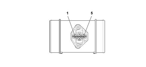
Debimeter connector pin out
1 - Temperature sensor
2 - Supply
3 - Earth
4 - Reference voltage (5V)
5 - Signal
The following table shows resistance values as a function of temperature
Temperature [°C]
Resistance (kohm]
minimum
rated
maximum
-40
35,140
39,260
43,760
-30
20,770
22,960
25,310
-20
12,660
13,850
15,120
-10
7,943
8,609
9,307
0
5,119
5,499
5,892
+10
3,384
3,604
3,829
+20
2,290
2,420
2,551
+30
1,573
1,662
1,752
+40
1,096
1,166
1,238
+50
0,779
0,835
0,892
+60
0,565
0,609
0,654
+70
0,416
0,452
0,488
+80
0,312
0,340
0,370
+90
0,238
0,261
0,285
+100
0,184
0,202
0,222
+110
0,144
0,159
0,176
+120
0,114
0,127
0,141
+130
0,091
0,102
0,114
The following diagram shows resistance level changes with changing temperature.
Air pressure - temperature sensor
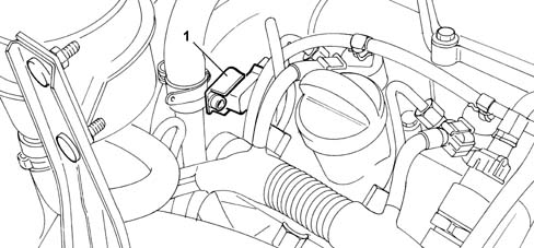
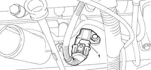
The air pressure/temperature sensor is located on the intake manifold and detects the level of turbocharged air pressure taken into the intake manifold.This value, combined with the air temperature sensor reading, allows the electronic control unit to determine the precise amount of air taken into the cylinders. The unit can then govern the injectors to modulate fuel delivery, limit harmful emissions and improve fuel consumption and performance.The sensor contains an electronic circuit that corrects temperature to optimise pressure detection as a function of intake air temperature. The sensor is fitted to the version without EGR.
1 - Air pressure/temperature sensor
Injectors
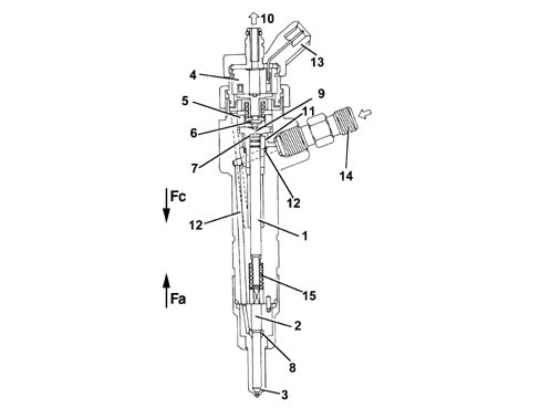
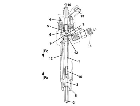
The injectors fitted to the cylinder head are electromagnetic and controlled directly by the engine control unit.The injectors are equipped with a high pressure supply duct (1600 bars) and an environmental ressure recirculation pipe. The supply duct is connected to the delivery manifold (rail) by means of pipes designed to support the high service pressures.The injector may be divided into two sections:
actuator/nebuliser consisting of pressure rod (1), pin (2) and nozzle (3);
control solenoid consisting of coil (4) and pilot valve (5).
Operation
Injector operation is divided into three stages:
Rest position: coil (4) is deactivated and plunger (6) is in closed position to prevent fuel from being introduced into the cylinder: Fc > Fa, where Fc is the force generated by the pressure acting on control area (7) of push-rod (1) and Fa is the force due to pressure acting in supply volume (8).
Injection start: coil (4) is excited and causes plunger (6) to rise. Fuel flows from control volume (9) to the return manifold to bring about a pressure drop on control area (7). Simultaneously, line pressure flowing through intake duct (12) exercises a force Fa > Fc in supply volume (8) to cause pin (2) to lift and allow fuel into the cylinders.
Injection end: Coil (4) is deactivated and causes plunger (6) to return to closed position. This rebalances the forces so that pin (2) returns to closed position and thus ends the injection.
1 - Push-rod.
2 - Pin.
3 - Nozzle.
4 - Coil.
5 - Pilot valve.
6 - Ball plunger.
7 - Control area.
8 - Supply volume.
9 - Control volume.
10 - Fuel outlet fitting (low pressure).
11 - Control duct.
12 - Supply duct.
13 - Electrical connection.
14 - Fuel intake fitting (high pressure).
15 - Spring.
Heater plugs check
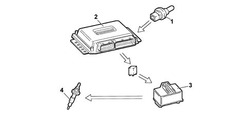
The engine control unit, during the following stages:
start-up
post-starting
applies a timer to the glow plug preheating control unit based on engine temperature.
1 - Engine coolant temperature sensor
2 - Engine management control unit
3 - Glow plug control unit
4 - Glow plugs
Glow plug electronic unit
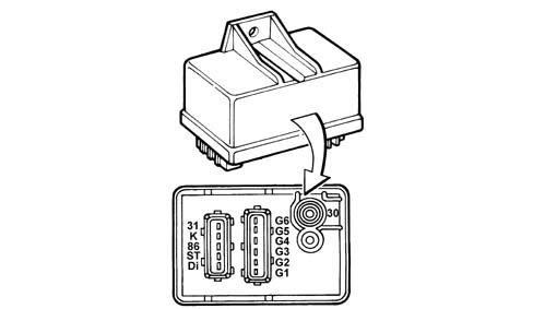
The glow plugs are controlled by the preheating control unit under the direct control of the engine control unit.The preheating control unit contains a smart relay that sends a return response (feedback) to the engine control unit. The unit is thus notified of possible faults in the preheating control unit or short-circuits to earth in the glow plugs.The figure shows the connectors at the preheating control unit base and the pin-out.
31 - Earth
K - Engine control unit
86 - Ignition switch (+15)
ST - Not connected
Di - Engine control unit
30 - Battery positive (+30)
G1 - Glow plugs
G2 - Glow plugs
G3 - Glow plugs
G4 - Glow plugs
G5 - Not connected
G6 - Not connected
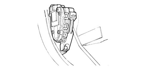
Accelerator pedal potentiometer
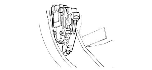
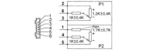
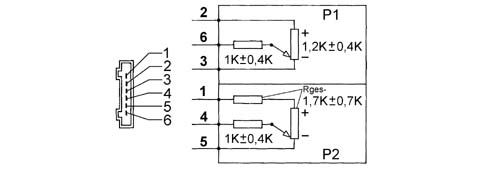
Accelerator pedal position is converted into an electrical voltage signal and sent to the engine control unit by a potentiometer on the pedal unit assembly.The accelerator pedal position sensor is used, together with rpm level, to establish injection times and relative fuel pressure.
1 - 5V positive.
2 - 5V positive.
3 - Negative.
4 - Analogue signal.
5 - Negative
6 - Analogue signal.
Accelerator pedal operation check
Connector the tester station (EXAMINER or SDC) to the input in the passenger compartment (facia junction unit).Move the accelerator pedal to the end of its travel (fully depressed).Record the accelerator pedal potentiometer output voltage.If the value measured is not within the range of 3.5 - 4.4 Volts, replace the pedal complete with potentiometer.Disconnect the tester station jack from the input in the passenger compartment (facia junction unit).
Brake pedal switch
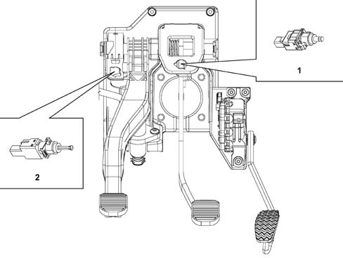
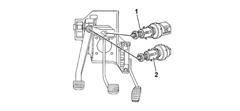
Switch (1) on the brake pedal controls the vehicle brake lights. The same switch sends a signal to pin A59 of the engine control unit.The control unit uses the "brake pedal depressed" signal to:
detect a situation of deceleration
check the veracity of the accelerator potentiometer output signal.
Clutch pedal switch
Switch (2) on the clutch pedal is connected to pin A61 of the engine control unit. The engine control unit uses the "clutch pedal operated" signal to distinguish between gear engaged and gear change conditions.
Atmospheric pressure sensor
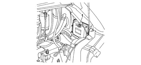
Atmospheric pressure sensor (1) built into the engine control unit measures atmospheric pressure with the aim of correcting measured air flow values and reference air flow values in order to control the EGR function.
Engines: 2.8 JTD 8V
INTRODUCTION
The Fiat Ducato commercial vehicle is equipped with a 2800 cc 4 cylinder in-line Bosch electronic injection turbodiesel engine with two valves per cylinder and one overhead camshafts. It is air turbocharged by means of a turbocharger and intercooler.The fuel system ensures the engine operates correctly and may be schematically broken down into the following circuits:
fuel supply circuit with Common Rail injection;
air supply circuit;
exhaust circuit;
crankcase oil vapour recirculation circuit;
exhaust gas recirculation circuit (EGR).
Operation of the various circuits that make up the fuel system is optimised by an electronic control system managed by a special control unit.The main feature of the fuel system is Common Rail fuel injection.The Common Rail system is a high pressure electronic injection circuit for fast, direct injection diesel engines.The main features of the Common Rail system are as follows:
availability of high pressure (up to 1350 bars);
possibility of modulating these pressures (from a minimum of 150 bars to a maximum of 1350 bars) independently of engine rotation speed (rpm) and load;
ability to work at high engine rpms (up to 5000 rpm);
injection control precision (injection advance and duration);
reduction in fuel consumption;
reduction in emissions.
FUEL SYSTEM MANAGEMENT STRATEGIES
The control unit memory contains a management programme (software) that includes a set of strategies, each of which manages a specific system control function.Each strategy uses information provided by the various sensors (input) to process a set of parameters that are based on data maps stored in special control unit memory areas. The strategy then controls system actuators (output) that allow the engine to operate.The main purpose of the management strategies is to calculate the exact amount of fuel to be injected into the cylinders. The associated timing (injection advance) and precision are set to ensure the best possible engine performance in terms of power, fuel consumption, fume emissions and vehicle handling.The main system management strategies are essentially as follows:
control of injected fuel quantity;
cylinder balance check when idling;
injetion advance control;
control of anti-judder function;
injection pressure control;
turbocharging control;
engine coolant temperature control;
fuel pre-feed pump control;
exhaust fume control;
injection control during over-run (cut-off);
maximum speed limit control;
idle speed control;
exhaust gas recirculation control (E.G.R.)
maximum torque limit control;
climate control system activation control;
self-diagnosis;
engine immobiliser function control.
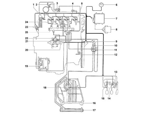
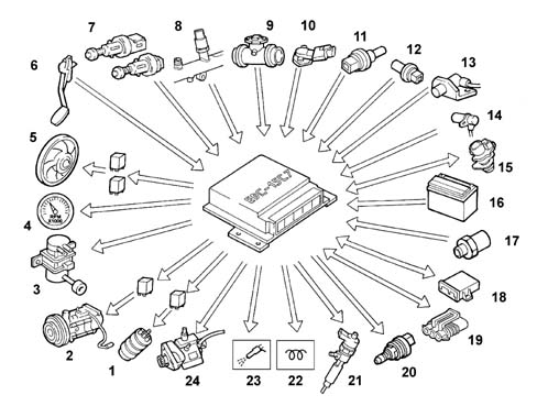
FUEL SYSTEM OPERATING DIAGRAM
The following figure shows the fuel system
1 - Timing sensor.
2 - Thermal starter.
3 - Solenoid for thermal starter.
4 - Air pressure/temperature sensor.
5 - Injector.
6 - Signal to rev counter from control unit.
7 - Bosch EDC 15C7 engine management unit.
8 - FIAT Code control unit.
9 - Fuel temperature sensor.
10 - Fuel preheater on filter.
11 - Fuel filter.
12 - Engine rpm sensor.
13 - Potentiometer on accelerator pedal.
14 - Sensor on brake pedal.
15 - Sensor on clutch pedal.
16 - Fuel tank.
17 - Fuel heating coil.
18 - Fuel pre-feed pump;
19 - Vehicle air conditioning system compressor.
20 - Fuel pressure regulator on high pressure pump.
21 - High pressure pump (Radialjet).
22 - 3rd pump element cut-out solenoid on high pressure pump.
23 - Coolant temperature sensors on thermostat.
24 - Fuel pressure sensor.
25 - Single manifold (rail).
Control of amount of fuel injected
The control unit manages the fuel pressure regulator and injectors on the basis of signals from the accelerator pedal potentiometer, debimeter and rpm sensor.Injection timing and sequence are determined upon engine start-up using signals from the engine rpm sensor and timing sensor (synchronisation stage). Injection timing is then implemented using the engine rpm sensor signal alone and considering the 1 - 3 - 4 - 2 injection sequence of the 2800 JTD engine.The control unit inhibits injection in the following cases:
Fuel pressure value greater than 1500 bar;
Fuel pressure value lower than 120 bar;
engine speed greater than 5000 rpm.
When the engine is warm, maximum injection duration (injector opening time) is 1500 % mgr;s. The duration may extend to 3000 %mgr;s during start-up.
Injection advance control
The electronic control unit determines injection advance mainly on the basis of the amount of fuel to be injected and engine speed.Injection advance is then corrected on the basis of engine coolant temperature in order to compensate for the increase in ignition delay due to low temperatures present in the combustion chambers during warm-up.
Injection pressure control
This control is important because injection pressure influences the following parameters:
amount of fuel taken into the cylinders for the same injection time duration;
nebulisation of fuel injected;
jet penetration;
delay between electric injector control and the effective start of fuel injection;
duration of fuel injection in the combustion chamber.
The above parameters influence engine behaviour crucially, particularly in terms of power supplied, exhaust emissions, noise and car handling.The engine control unit controls the pressure regulator as required on the basis of engine load and engine speed to ensure optimal line pressure at all times.When the engine is cold, injection pressure is corrected on the basis of coolant temperature to meet engine requirements at different service temperatures.
Control of electric fuel pre-supply pump
The auxiliary fuel pump submerged in the tank is supplied by the engine control unit via a relay when the ignition key is in MAR position.The pump supply is inhibited under the following circumstances:
after the ignition key has been in ON position for a certain time and the engine is not operating;
if the inertia switch has gone off.
Injection control during over-run (cut-off)
The fuel cut-off strategy is implemented when the engine control unit receives information from the potentiometer, which sends a signal to indicate that the accelerator pedal has been released by the user.Under these conditions, the control unit cuts off the power supply to the injectors and reactivates it before reaching idle speed. It also controls the fuel pressure regulator.
Idle speed control
The injection control unit controls the pressure regulator and alters injector opening times on the basis of signals from the engine rpm sensor and coolant temperature sensor to keep idle speed stable. Under certain conditions, the control unit takes battery voltage into account to control idle speed.
Maximum speed limit control
The engine control unit intervenes in two ways to limit maximum speed on the basis of rpm:
as maximum speed approaches (4200 rpm), the amount of fuel injected falls and line pressure is reduced;
injector operation is inhibited at speeds over 5000 rpm.
Maximum torque limit control
The injection control unit calculates limit torque and maximum permitted fume index parameters according to rpm. The calculations are based on predefined maps stored in its memory. The control unit corrects the above parameters using engine coolant and vehicle speed data and uses the resulting values to modulate the amount of fuel to be injected by adjusting the pressure regulator and injectors.
Control of fuel temperature
The injection control unit is constantly informed of fuel temperature by means of a specific sensor in the fuel filter.If fuel temperature exceeds a certain level (about 85 - 90 °C), the control unit reduces line pressure by adjusting the pressure regulator and leaving the injection times the same.
Engine coolant temperature control
The injection control unit is constantly informed of coolant temperature by means of a sensor on the thermostat.If engine coolant temperature exceeds certain levels, the control unit takes the following actions:
reduces fuel quantity by adjusting the pressure regulator or injectors (power reduction);
drives the engine radiator cooling fan.
When the ignition key is turned to STOP (if the temperature exceeds the cooling system activation threshold), the fan stays on for a maximum time of 20 seconds to take the temperature below the cooling system activation threshold.When the ignition key is turned to the ON position. (coolant temperature exceeds the cooling system activation threshold), the fans do not activate until engine rpm exceeds 770 rpm. (engine speed when warm is 780 rpm).
Exhaust fume control
The injection control unit limits any exhaust fumes that could occur during hard acceleration.To meet this requirement, the control unit processes signals from the accelerator pedal potentiometer, engine rpm sensor and intake air quantity sensor (debimeter); the inejction control unit controls the fuel pressure regulator and injectors to modulate the amount of fuel to be injected into the combustion chamber and reduce exhaust fume levels.
Exhaust gas recirculation control (for versions without variable geometry turbine)
The injection control unit, on the basis of signals supplied: by sensors measuring engine rpm, intake air quantity (debimeter), engine coolant temperature and accelerator pedal position, controls EGR valve activation to achieve partial exhaust gas recirculation only under certain engine service conditions.
Supercharging pressure control
- The injection control unit processes the signal from the supercharging pressure, at the various engine operating speeds and determines the quantity of fuel to inject:
controls the pressure regulator
alters the injection time
controls the VGT valve in order to vary the geometry of the turbine in order to guarantee optimum performance in all operating conditions.
Control of air conditioning system activation
The engine control unit manages the vehicle air conditioning system compressor electromagnetic coupling by pursuing a strategy that prevents engine performance being penalised while the air conditioner is being used.When the compressor is activated, the engine control unit increases the amount of fuel at idle speed to adjust the engine to the higher power requirement and cut off power supply to the compressor under conditions of:
high power demand from the engine (hard acceleration);
engine coolant overheating.
Engine immobiliser function control
The system is equipped with an engine immobiliser. This function is executed by a control unit (Fiat CODE) able to communicate with the engine control unit and an electronic key with a transmitter that sends out a recognition code. Whenever the key is turned OFF, the Fiat CODE system fully deactivates the engine control unit.When the key is turned ON, the following operations take place in sequence:
the engine control unit (with the secret code in its memory) sends the Fiat CODE control unit a secret code request that deactivates the function lock;
the Fiat CODE control unit responds by sending back the secret code only once it has received, in turn, a recognition code sent by the ignition key.
secret code recognition allows engine control unit lock deactivation and resumption of normal operation.
Self-diagnosis
Full injection system electronic diagnosis is carried out by connecting an appropriate tester (EXAMINER or SDC station) to the tester input located in the engine bay.The system also comes with a self-diagnostic function that detects, stores and indicates faults.If a fault is detected in a sensor or actuator, signal reconstruction strategies (recovery) are immediately activated to ensure the engine operates at an acceptable level without impairing service. The vehicle can therefore be driven to a service outlet for the necessary repairs.
BOSCH EDC 15C7 ENGINE CONTROL UNIT
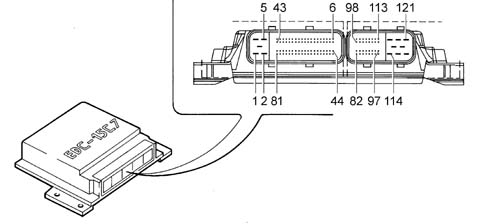
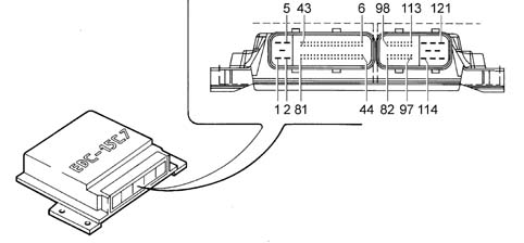
The EDC 15C7 processes signals from the sensors by applying software algorithms and controls actuators (particularly the injectors and pressure regulator) to achieve the most effective possible engine operation.The control unit is flash E.P.R.O.M. type and can be reprogrammed externally without the need to adjust the hardware.The engine control unit contains a built-in atmospheric pressure sensor and is connected to the wiring by means of 2 connectors that provide a total of 121 pins.
Identification of EDC15 C7 engine management control unit connections
Currently available versions are:
2.8 JTD engine with Heat - flange with EGR;
2.8 JTD with Heat - flange without EGR;
2.8 JTD with thermal starter without EGR.
2.8 JTD with thermal starter with EGR.
2.8 JTD engine with Heat - flange with VGT, without EGR;
2.8 JTD with thermal starter with VGT, without EGR.
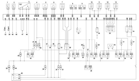
Version with Heat - flange with EGR
Pin Out
A1 - Chassis earth.
A2 - Chassis earth.
A3 - Chassis earth.
A4 - Fuel pump relay coil supply.
A5 - Power supply from main relay.
A6 - Not connected.
A7 - Not connected.
A8 - Not connected.
A9 - C-Can L.
A10 - C-Can H.
A11 - Fiat CODE control unit.
A12 - Not connected.
A15 - Power supply to main relay coil.
A14 - Preheating indicator control relay coil power supply.
A15 - Heat flange relay coil power supply.
A16 - EGR solenoid control.
A17 - Not connected.
A18 - Power supply to compressor relay coil.
A19 - Power supply for engine cooling fan control relays.
A20 - Power supply to engine cooling fan relay (low speed)
A21 - Instrument panel (MIL).
A22 - Not connected.
A23 - Cruise Control activation warning light.
A24 - Fuel pump relay coil supply.
A25 - Not connected.
A26 - Not connected.
A27 - Not connected.
A28 - Not connected.
A29 - Not connected.
A30 - Not connected.
A31 - Not connected.
A32 - Not connected.
A33 - Not connected.
A34 - Not connected.
A35 - Not connected.
A36 - Not connected.
A37 - Not connected.
A38 - Not connected.
A39 - Not connected.
A40 - Not connected.
A41 - Not connected.
A42 - Not connected.
A43 - Not connected.
A44 - Not connected.
A45 - Not connected.
A46 - Not connected.
A47 - Instrument panel (engine rpm).
A48 - Tester input.
A49 - From pulse generator (for speedometer).
A50 - Not connected.
A51 - 4 stage pressure switch.
A52 - 4 stage pressure switch.
A53 - Cruise Control ON.
A54 - Vehicle brake light control.
A55 - Cruise Control resume.
A56 - Cruise Control set - .
A57 - Cruise Control set +.
A58 - From Fiat CODE control unit.
A59 - Vehicle brake light control.
A60 - 4 stage pressure switch.
A61 - Sensor on clutch pedal.
A62 - Not connected.
A63 - Not connected.
A64 - Not connected.
A65 - Not connected.
A66 - Not connected.
A67 - Not connected.
A68 - Not connected.
A69 - Not connected.
A70 - Not connected.
A71 - Not connected.
A72 - Not connected.
A73 - Not connected.
A74 - Not connected.
A75 - Not connected.
A76 - Potentiometer on accelerator pedal.
A77 - Potentiometer on accelerator pedal.
A78 - Potentiometer on accelerator pedal.
A79 - Potentiometer on accelerator pedal.
A80 - Potentiometer on accelerator pedal.
A81 - Potentiometer on accelerator pedal.
B82 - Fuel temperature sensor.
B83 - Fuel temperature sensor.
B84 - Engine coolant temperature sensor.
B85 - Engine coolant temperature sensor.
B86 - Air flow meter (debimeter).
B87 - Not connected.
B88 - Air flow meter (debimeter).
B89 - Air flow meter (debimeter).
B90 - Fuel pressure sensor.
B91 - Fuel pressure sensor.
B92 - Fuel pressure sensor.
B93 - Not connected.
B94 - Not connected.
B95 - Not connected.
B96 - Not connected.
B97 - Air flow meter (debimeter).
B98 - Not connected.
B99 - Engine rpm sensor.
B100 - Engine rpm sensor.
B101 - Engine rpm sensor.
B102 - Timing sensor.
B103 - Timing sensor.
B104 - Timing sensor.
B105 - Not connected.
B106 - Not connected.
B107 - Not connected.
B108 - Fuel pressure regulator.
B109 - Fuel pressure regulator.
B110 - Fuel filter heater relay control.
B111 - 3rd pump element cut-out solenoid.
B112 - Not connected.
B113 - Not connected.
B114 - Cylinder no. 4 injector.
B115 - Not connected.
B116 - Not connected.
B117 - Cylinder no. 1 and no. 2 injector return
B118 - Cylinder no. 3 and no. 4 injector return
B119 - Cylinder no. 1 injector.
B120 - Cylinder no. 2 injector.
B121 - Cylinder no. 3 injector.
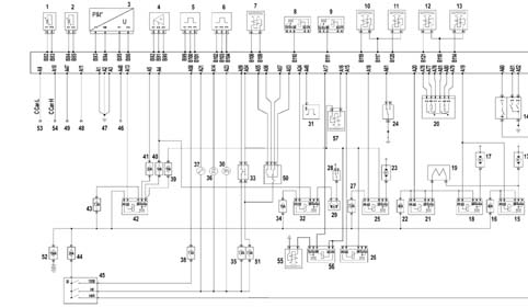
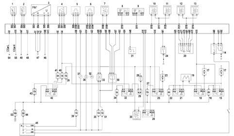
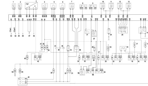
Injection system wiring diagram with Heat - flange with EGR
1 - Fuel temperature sensor.
2 - Engine coolant temperature sensor.
3 - Air flow meter (debimeter).
4 - Fuel pressure sensor.
5 - Engine rpm sensor.
6 - Timing sensor.
7 - Fuel pressure regulator.
8 - Fuel filter heater relay.
9 - 3rd pump element cut-out solenoid.
10 - Cylinder no. 1 injector.
11 - Cylinder no. 2 injector.
12 - Cylinder no. 3 injector.
13 - Cylinder no. 4 injector.
14 - 4 stage pressure switch.
15 - Engine cooling relay (high speed)
16 - 40 A fuse.
17 - Engine cooling fan.
18 - Engine cooling relay (high speed)
19 - Resistor.
20 - Potentiometer on accelerator pedal.
21 - Engine cooling relay (low speed)
22 - 40 A fuse.
23 - Compressor.
24 - Sensor on clutch pedal.
25 - Compressor control relay.
26 - Heat - flange control relay.
27 - 7.5 A fuse.
28 - Inertia switch.
29 - Electric pump submerged in tank.
30 - EGR solenoid.
31 - Pulse generator.
32 - Relay controlling electric pump submerged in tank.
33 - Vehicle brake light control.
34 - 15 A fuse.
35 - 7.5 A fuse.
36 - Preheating warning light.
37 - Injection system failure warning light.
38 - 7.5 A fuse.
39 - 15 A fuse.
40 - 10 A fuse.
41 - 20 A fuse.
42 - Main relay.
43 - 7.5 A fuse.
44 - 20 A fuse.
45 - Ignition switch.
46 - Tester input.
47 - Chassis earth.
48 - Fiat CODE control unit.
49 - Signal for rev counter on instrument panel.
50 - Cruise control
51 - 7.5 A fuse.
52 - Cruise Control activation warning light.
53 - 150 A fuse.
54 - C-Can L network.
55 - C-Can H network.
Version with Heat - flange without EGR
Pin Out
A1 - Chassis earth.
A2 - Chassis earth.
A3 - Chassis earth.
A4 - Fuel pump relay coil supply.
A5 - Power supply from main relay.
A6 - Not connected.
A7 - Not connected.
A8 - Not connected.
A9 - C-Can L.
A10 - C-Can H.
A11 - Fiat CODE control unit.
A12 - Not connected.
A15 - Power supply to main relay coil.
A14 - Preheating indicator control relay coil power supply.
A15 - Heat flange relay coil power supply.
A16 - Not connected.
A17 - Not connected.
A18 - Power supply to compressor relay coil.
A19 - Power supply for engine cooling fan control relays.
A20 - Power supply to engine cooling fan relay (low speed)
A21 - Instrument panel (MIL).
A22 - Not connected.
A23 - Cruise Control activation warning light.
A24 - Fuel pump relay coil supply.
A25 - Not connected.
A26 - Not connected.
A27 - Not connected.
A28 - Not connected.
A29 - Not connected.
A30 - Not connected.
A31 - Not connected.
A32 - Not connected.
A33 - Not connected.
A34 - Not connected.
A35 - Not connected.
A36 - Not connected.
A37 - Not connected.
A38 - Not connected.
A39 - Not connected.
A40 - Not connected.
A41 - Not connected.
A42 - Not connected.
A43 - Not connected.
A44 - Not connected.
A45 - Not connected.
A46 - Not connected.
A47 - Instrument panel (engine rpm).
A48 - Tester input.
A49 - From pulse generator (for speedometer).
A50 - Not connected.
A51 - 4 stage pressure switch.
A52 - 4 stage pressure switch.
A53 - Cruise Control ON.
A54 - Vehicle brake light control.
A55 - Cruise Control resume.
A56 - Cruise Control set - .
A57 - Cruise Control set +.
A58 - From Fiat CODE control unit.
A59 - Vehicle brake light control.
A60 - 4 stage pressure switch.
A61 - Sensor on clutch pedal.
A62 - Not connected.
A63 - Not connected.
A64 - Not connected.
A65 - Not connected.
A66 - Not connected.
A67 - Not connected.
A68 - Not connected.
A69 - Not connected.
A70 - Not connected.
A71 - Not connected.
A72 - Not connected.
A73 - Not connected.
A74 - Not connected.
A75 - Not connected.
A76 - Potentiometer on accelerator pedal.
A77 - Potentiometer on accelerator pedal.
A78 - Potentiometer on accelerator pedal.
A79 - Potentiometer on accelerator pedal.
A80 - Potentiometer on accelerator pedal.
A81 - Potentiometer on accelerator pedal.
B82 - Fuel temperature sensor.
B83 - Fuel temperature sensor.
B84 - Engine coolant temperature sensor.
B85 - Engine coolant temperature sensor.
B86 - Air pressure/temperature sensor.
B87 - Not connected.
B88 - Not connected.
B89 - Not connected.
B90 - Fuel pressure sensor.
B91 - Fuel pressure sensor.
B92 - Fuel pressure sensor.
B93 - Air pressure/temperature sensor.
B94 - Air pressure/temperature sensor.
B95 - Air pressure/temperature sensor.
B96 - Not connected.
B97 - Not connected.
B98 - Not connected.
B99 - Engine rpm sensor.
B100 - Engine rpm sensor.
B101 - Engine rpm sensor.
B102 - Timing sensor.
B103 - Timing sensor.
B104 - Timing sensor.
B105 - Not connected.
B106 - Not connected.
B107 - Not connected.
B108 - Fuel pressure regulator.
B109 - Fuel pressure regulator.
B110 - Fuel filter heater relay control.
B111 - 3rd pump element cut-out solenoid.
B112 - Not connected.
B113 - Not connected.
B114 - Cylinder no. 4 injector.
B115 - Not connected.
B116 - Not connected.
B117 - Cylinder no. 1 and no. 2 injector return
B118 - Cylinder no. 3 and no. 4 injector return
B119 - Cylinder no. 1 injector.
B120 - Cylinder no. 2 injector.
B121 - Cylinder no. 3 injector.
Injection system wiring diagram with Heat - flange without EGR
1 - Fuel temperature sensor.
2 - Engine coolant temperature sensor.
3 - Air pressure - temperature sensor in intake manifold.
4 - Fuel pressure sensor.
5 - Engine rpm sensor.
6 - Timing sensor.
7 - Fuel pressure regulator.
8 - Fuel filter heater relay.
9 - 3rd pump element cut-out solenoid.
10 - Cylinder no. 1 injector.
11 - Cylinder no. 2 injector.
12 - Cylinder no. 3 injector.
13 - Cylinder no. 4 injector.
14 - 4 stage pressure switch.
15 - Engine cooling relay (high speed)
16 - 40 A fuse.
17 - Engine cooling fan.
18 - Engine cooling relay (high speed)
19 - Resistor.
20 - Potentiometer on accelerator pedal.
21 - Engine cooling relay (low speed)
22 - 40 A fuse.
23 - Compressor.
24 - Sensor on clutch pedal.
25 - Compressor control relay.
26 - Heat - flange control relay.
27 - 7.5 A fuse.
28 - Inertia switch.
29 - Electric pump submerged in tank.
30 - Cruise Control activation warning light.
31 - Pulse generator.
32 - Relay controlling electric pump submerged in tank.
33 - Vehicle brake light control.
34 - 15 A fuse.
35 - 7.5 A fuse.
36 - Preheating warning light.
37 - Injection system failure warning light.
38 - 7.5 A fuse.
39 - 15 A fuse.
40 - 10 A fuse.
41 - 20 A fuse.
42 - Main relay.
43 - 7.5 A fuse.
44 - 20 A fuse.
45 - Ignition switch.
46 - Tester input.
47 - Chassis earth.
48 - Fiat CODE control unit.
49 - Signal for rev counter on instrument panel.
50 - Cruise control
51 - 7.5 A fuse.
52 - 150 A fuse.
53 - C-Can L network.
54 - C-Can H network.
Version with thermal starter without EGR
Pin Out
A1 - Chassis earth.
A2 - Chassis earth.
A3 - Chassis earth.
A4 - Fuel pump relay coil supply.
A5 - Power supply from main relay.
A6 - Not connected.
A7 - Not connected.
A8 - Not connected.
A9 - C-Can L.
A10 - C-Can H.
A11 - Fiat CODE control unit.
A12 - Not connected.
A15 - Power supply to main relay coil.
A14 - Preheating indicator control relay coil power supply.
A15 - Power supply to thermal starter relay coil.
A16 - Not connected.
A15 - Power supply to thermal starter solenoid coil.
A18 - Power supply to compressor relay coil.
A19 - Power supply for engine cooling fan control relays.
A20 - Power supply to engine cooling fan relay (low speed)
A21 - Instrument panel (MIL).
A22 - Not connected.
A23 - Cruise Control activation warning light.
A24 - Fuel pump relay coil supply.
A25 - Not connected.
A26 - Not connected.
A27 - Not connected.
A28 - Not connected.
A29 - Not connected.
A30 - Not connected.
A31 - Not connected.
A32 - Not connected.
A33 - Not connected.
A34 - Not connected.
A35 - Not connected.
A36 - Not connected.
A37 - Not connected.
A38 - Not connected.
A39 - Not connected.
A40 - Not connected.
A41 - Not connected.
A42 - Not connected.
A43 - Not connected.
A44 - Not connected.
A45 - Not connected.
A46 - Not connected.
A47 - Instrument panel (engine rpm).
A48 - Tester input.
A49 - From pulse generator (for speedometer).
A50 - Not connected.
A51 - 4 stage pressure switch.
A52 - 4 stage pressure switch.
A53 - Cruise Control ON.
A54 - Vehicle brake light control.
A55 - Cruise Control resume.
A56 - Cruise Control set - .
A57 - Cruise Control set +.
A58 - From Fiat CODE control unit.
A59 - Vehicle brake light control.
A60 - 4 stage pressure switch.
A61 - Sensor on clutch pedal.
A62 - Not connected.
A63 - Not connected.
A64 - Not connected.
A65 - Not connected.
A66 - Not connected.
A67 - Not connected.
A68 - Not connected.
A69 - Not connected.
A70 - Not connected.
A71 - Not connected.
A72 - Not connected.
A73 - Not connected.
A74 - Not connected.
A75 - Not connected.
A76 - Potentiometer on accelerator pedal.
A77 - Potentiometer on accelerator pedal.
A78 - Potentiometer on accelerator pedal.
A79 - Potentiometer on accelerator pedal.
A80 - Potentiometer on accelerator pedal.
A81 - Potentiometer on accelerator pedal.
B82 - Fuel temperature sensor.
B83 - Fuel temperature sensor.
B84 - Engine coolant temperature sensor.
B85 - Engine coolant temperature sensor.
B86 - Air pressure/temperature sensor.
B87 - Not connected.
B88 - Not connected.
B89 - Not connected.
B90 - Fuel pressure sensor.
B91 - Fuel pressure sensor.
B92 - Fuel pressure sensor.
B93 - Air pressure/temperature sensor.
B94 - Air pressure/temperature sensor.
B95 - Air pressure/temperature sensor.
B96 - Not connected.
B97 - Not connected.
B98 - Not connected.
B99 - Engine rpm sensor.
B100 - Engine rpm sensor.
B101 - Engine rpm sensor.
B102 - Timing sensor.
B103 - Timing sensor.
B104 - Timing sensor.
B105 - Not connected.
B106 - Not connected.
B107 - Not connected.
B108 - Fuel pressure regulator.
B109 - Fuel pressure regulator.
B110 - Fuel filter heater relay control.
B111 - 3rd pump element cut-out solenoid.
B112 - Not connected.
B113 - Not connected.
B114 - Cylinder no. 4 injector.
B115 - Not connected.
B116 - Not connected.
B117 - Cylinder no. 1 and no. 2 injector return
B118 - Cylinder no. 3 and no. 4 injector return
B119 - Cylinder no. 1 injector.
B120 - Cylinder no. 2 injector.
B121 - Cylinder no. 3 injector.
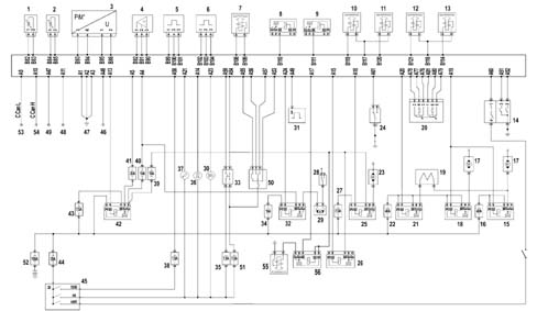
Diagram showing injection system with thermal starter without EGR
1 - Fuel temperature sensor.
2 - Engine coolant temperature sensor.
3 - Air pressure - temperature sensor in intake manifold.
4 - Fuel pressure sensor.
5 - Engine rpm sensor.
6 - Timing sensor.
7 - Fuel pressure regulator.
8 - Fuel filter heater relay.
9 - 3rd pump element cut-out solenoid.
10 - Cylinder no. 1 injector.
11 - Cylinder no. 2 injector.
12 - Cylinder no. 3 injector.
13 - Cylinder no. 4 injector.
14 - 4 stage pressure switch.
15 - Engine cooling relay (high speed)
16 - 40 A fuse.
17 - Engine cooling fan.
18 - Engine cooling relay (high speed)
19 - Resistor.
20 - Potentiometer on accelerator pedal.
21 - Engine cooling relay (low speed)
22 - 40 A fuse.
23 - Compressor.
24 - Sensor on clutch pedal.
25 - Compressor control relay.
26 - Thermal starter control relay.
27 - 7.5 A fuse.
28 - Inertia switch.
29 - Electric pump submerged in tank.
30 - Cruise Control activation warning light.
31 - Pulse generator.
32 - Relay controlling electric pump submerged in tank.
33 - Vehicle brake light control.
34 - 15 A fuse.
35 - 7.5 A fuse.
36 - Preheating warning light.
37 - Injection system failure warning light.
38 - 7.5 A fuse.
39 - 15 A fuse.
40 - 10 A fuse.
41 - 20 A fuse.
42 - Main relay.
43 - 7.5 A fuse.
44 - 20 A fuse.
45 - Ignition switch.
46 - Tester input.
47 - Chassis earth.
48 - Fiat CODE control unit.
49 - Signal for rev counter on instrument panel.
50 - Cruise control
51 - 7.5 A fuse.
52 - 150 A fuse.
53 - C-Can L network.
54 - C-Can H network.
55 - Thermal starter solenoid.
56 - Thermal starter solenoid control relay.
Version with thermal starter with EGR
Pin Out
A1 - Chassis earth.
A2 - Chassis earth.
A3 - Chassis earth.
A4 - Fuel pump relay coil supply.
A5 - Power supply from main relay.
A6 - Not connected.
A7 - Not connected.
A8 - Not connected.
A9 - C-Can L.
A10 - C-Can H.
A11 - Fiat CODE control unit.
A12 - Not connected.
A15 - Power supply to main relay coil.
A14 - Preheating indicator control relay coil power supply.
A15 - Power supply to thermal starter relay coil.
A16 - EGR solenoid control.
A15 - Power supply to thermal starter solenoid coil.
A18 - Power supply to compressor relay coil.
A19 - Power supply for engine cooling fan control relays.
A20 - Power supply to engine cooling fan relay (low speed)
A21 - Instrument panel (MIL).
A22 - Not connected.
A23 - Cruise Control activation warning light.
A24 - Fuel pump relay coil supply.
A25 - Not connected.
A26 - Not connected.
A27 - Not connected.
A28 - Not connected.
A29 - Not connected.
A30 - Not connected.
A31 - Not connected.
A32 - Not connected.
A33 - Not connected.
A34 - Not connected.
A35 - Not connected.
A36 - Not connected.
A37 - Not connected.
A38 - Not connected.
A39 - Not connected.
A40 - Not connected.
A41 - Not connected.
A42 - Not connected.
A43 - Not connected.
A44 - Not connected.
A45 - Not connected.
A46 - Not connected.
A47 - Instrument panel (engine rpm).
A48 - Tester input.
A49 - From pulse generator (for speedometer).
A50 - Not connected.
A51 - 4 stage pressure switch.
A52 - 4 stage pressure switch.
A53 - Cruise Control ON.
A54 - Vehicle brake light control.
A55 - Cruise Control resume.
A56 - Cruise Control set - .
A57 - Cruise Control set +.
A58 - From Fiat CODE control unit.
A59 - Vehicle brake light control.
A60 - 4 stage pressure switch.
A61 - Sensor on clutch pedal.
A62 - Not connected.
A63 - Not connected.
A64 - Not connected.
A65 - Not connected.
A66 - Not connected.
A67 - Not connected.
A68 - Not connected.
A69 - Not connected.
A70 - Not connected.
A71 - Not connected.
A72 - Not connected.
A73 - Not connected.
A74 - Not connected.
A75 - Not connected.
A76 - Potentiometer on accelerator pedal.
A77 - Potentiometer on accelerator pedal.
A78 - Potentiometer on accelerator pedal.
A79 - Potentiometer on accelerator pedal.
A80 - Potentiometer on accelerator pedal.
A81 - Potentiometer on accelerator pedal.
B82 - Fuel temperature sensor.
B83 - Fuel temperature sensor.
B84 - Engine coolant temperature sensor.
B85 - Engine coolant temperature sensor.
B86 - Air pressure/temperature sensor.
B87 - Not connected.
B88 - Not connected.
B89 - Not connected.
B90 - Fuel pressure sensor.
B91 - Fuel pressure sensor.
B92 - Fuel pressure sensor.
B93 - Air pressure/temperature sensor.
B94 - Air pressure/temperature sensor.
B95 - Air pressure/temperature sensor.
B96 - Not connected.
B97 - Not connected.
B98 - Not connected.
B99 - Engine rpm sensor.
B100 - Engine rpm sensor.
B101 - Engine rpm sensor.
B102 - Timing sensor.
B103 - Timing sensor.
B104 - Timing sensor.
B105 - Not connected.
B106 - Not connected.
B107 - Not connected.
B108 - Fuel pressure regulator.
B109 - Fuel pressure regulator.
B110 - Fuel filter heater relay control.
B111 - 3rd pump element cut-out solenoid.
B112 - Not connected.
B113 - Not connected.
B114 - Cylinder no. 4 injector.
B115 - Not connected.
B116 - Not connected.
B117 - Cylinder no. 1 and no. 2 injector return
B118 - Cylinder no. 3 and no. 4 injector return
B119 - Cylinder no. 1 injector.
B120 - Cylinder no. 2 injector.
B121 - Cylinder no. 3 injector.
Diagram showing injection system with thermal starter with EGR
1 - Fuel temperature sensor.
2 - Engine coolant temperature sensor.
3 - Air pressure - temperature sensor in intake manifold.
4 - Fuel pressure sensor.
5 - Engine rpm sensor.
6 - Timing sensor.
7 - Fuel pressure regulator.
8 - Fuel filter heater relay.
9 - 3rd pump element cut-out solenoid.
10 - Cylinder no. 1 injector.
11 - Cylinder no. 2 injector.
12 - Cylinder no. 3 injector.
13 - Cylinder no. 4 injector.
14 - 4 stage pressure switch.
15 - Engine cooling relay (high speed)
16 - 40 A fuse.
17 - Engine cooling fan.
18 - Engine cooling relay (high speed)
19 - Resistor.
20 - Potentiometer on accelerator pedal.
21 - Engine cooling relay (low speed)
22 - 40 A fuse.
23 - Compressor.
24 - Sensor on clutch pedal.
25 - Compressor control relay.
26 - Thermal starter control relay.
27 - 7.5 A fuse.
28 - Inertia switch.
29 - Electric pump submerged in tank.
30 - Cruise Control activation warning light.
31 - Pulse generator.
32 - Relay controlling electric pump submerged in tank.
33 - Vehicle brake light control.
34 - 15 A fuse.
35 - 7.5 A fuse.
36 - Preheating warning light.
37 - Injection system failure warning light.
38 - 7.5 A fuse.
39 - 15 A fuse.
40 - 10 A fuse.
41 - 20 A fuse.
42 - Main relay.
43 - 7.5 A fuse.
44 - 20 A fuse.
45 - Ignition switch.
46 - Tester input.
47 - Chassis earth.
48 - Fiat CODE control unit.
49 - Signal for rev counter on instrument panel.
50 - Cruise control
51 - 7.5 A fuse.
52 - 150 A fuse.
53 - C-Can L network.
54 - C-Can H network.
55 - Thermal starter solenoid.
56 - Thermal starter solenoid control relay.
57 - EGR solenoid valve
Version with Heat - flange with VGT
Pin Out
A1 - Chassis earth.
A2 - Chassis earth.
A3 - Chassis earth.
A4 - Fuel pump relay coil supply.
A5 - Power supply from main relay.
A6 - Not connected.
A7 - Not connected.
A8 - Not connected.
A9 - C-Can L.
A10 - C-Can H.
A11 - Fiat CODE control unit.
A12 - Not connected.
A15 - Power supply to main relay coil.
A14 - Preheating indicator control relay coil power supply.
A15 - Heat flange relay coil power supply.
A16 - VGT solenoid control.
A17 - Not connected.
A18 - Power supply to compressor relay coil.
A19 - Power supply for engine cooling fan control relays.
A20 - Power supply to engine cooling fan relay (low speed)
A21 - Instrument panel (MIL).
A22 - Not connected.
A23 - Cruise Control activation warning light.
A24 - Fuel pump relay coil supply.
A25 - Not connected.
A26 - Not connected.
A27 - Not connected.
A28 - Not connected.
A29 - Not connected.
A30 - Not connected.
A31 - Not connected.
A32 - Not connected.
A33 - Not connected.
A34 - Not connected.
A35 - Not connected.
A36 - Not connected.
A37 - Not connected.
A38 - Not connected.
A39 - Not connected.
A40 - Not connected.
A41 - Not connected.
A42 - Not connected.
A43 - Not connected.
A44 - Not connected.
A45 - Not connected.
A46 - Not connected.
A47 - Instrument panel (engine rpm).
A48 - Tester input.
A49 - From pulse generator (for speedometer).
A50 - Not connected.
A51 - 4 stage pressure switch.
A52 - 4 stage pressure switch.
A53 - Cruise Control ON.
A54 - Vehicle brake light control.
A55 - Cruise Control resume.
A56 - Cruise Control set - .
A57 - Cruise Control set +.
A58 - From Fiat CODE control unit.
A59 - Vehicle brake light control.
A60 - 4 stage pressure switch.
A61 - Sensor on clutch pedal.
A62 - Not connected.
A63 - Not connected.
A64 - Not connected.
A65 - Not connected.
A66 - Not connected.
A67 - Not connected.
A68 - Not connected.
A69 - Not connected.
A70 - Not connected.
A71 - Not connected.
A72 - Not connected.
A73 - Not connected.
A74 - Not connected.
A75 - Not connected.
A76 - Potentiometer on accelerator pedal.
A77 - Potentiometer on accelerator pedal.
A78 - Potentiometer on accelerator pedal.
A79 - Potentiometer on accelerator pedal.
A80 - Potentiometer on accelerator pedal.
A81 - Potentiometer on accelerator pedal.
B82 - Fuel temperature sensor.
B83 - Fuel temperature sensor.
B84 - Engine coolant temperature sensor.
B85 - Engine coolant temperature sensor.
B86 - Air pressure and temperature sensor.
B87 - Not connected.
B88 - Not connected.
B89 - Not connected.
B90 - Fuel pressure sensor.
B91 - Fuel pressure sensor.
B92 - Fuel pressure sensor.
B93 - Air pressure and temperature sensor.
B94 - Air pressure and temperature sensor.
B95 - Air pressure and temperature sensor.
B96 - Not connected.
B97 - Not connected.
B98 - Not connected.
B99 - Engine rpm sensor.
B100 - Engine rpm sensor.
B101 - Engine rpm sensor.
B102 - Timing sensor.
B103 - Timing sensor.
B104 - Timing sensor.
B105 - Not connected.
B106 - Not connected.
B107 - Not connected.
B108 - Fuel pressure regulator.
B109 - Fuel pressure regulator.
B110 - Fuel filter heater relay control.
B111 - 3rd pump element cut-out solenoid.
B112 - Not connected.
B113 - Not connected.
B114 - Cylinder no. 4 injector.
B115 - Not connected.
B116 - Not connected.
B117 - Cylinder no. 1 and no. 2 injector return
B118 - Cylinder no. 3 and no. 4 injector return
B119 - Cylinder no. 1 injector.
B120 - Cylinder no. 2 injector.
B121 - Cylinder no. 3 injector.
Injection system wiring diagram with Heat - flange with VGT
1 - Fuel temperature sensor.
2 - Engine coolant temperature sensor.
3 - Air pressure and temperature sensor.
4 - Fuel pressure sensor.
5 - Engine rpm sensor.
6 - Timing sensor.
7 - Fuel pressure regulator.
8 - Fuel filter heater relay.
9 - 3rd pump element cut-out solenoid.
10 - Cylinder no. 1 injector.
11 - Cylinder no. 2 injector.
12 - Cylinder no. 3 injector.
13 - Cylinder no. 4 injector.
14 - 4 stage pressure switch.
15 - Engine cooling relay (high speed)
16 - 40 A fuse.
17 - Engine cooling fan.
18 - Engine cooling relay (high speed)
19 - Resistor.
20 - Potentiometer on accelerator pedal.
21 - Engine cooling relay (low speed)
22 - 40 A fuse.
23 - Compressor.
24 - Sensor on clutch pedal.
25 - Compressor control relay.
26 - Heat - flange control relay.
27 - 7.5 A fuse.
28 - Inertia switch.
29 - Electric pump submerged in tank.
30 - VGT solenoid valve.
31 - Pulse generator.
32 - Relay controlling electric pump submerged in tank.
33 - Vehicle brake light control.
34 - 15 A fuse.
35 - 7.5 A fuse.
36 - Preheating warning light.
37 - Injection system failure warning light.
38 - 7.5 A fuse.
39 - 15 A fuse.
40 - 10 A fuse.
41 - 20 A fuse.
42 - Main relay.
43 - 7.5 A fuse.
44 - 20 A fuse.
45 - Ignition switch.
46 - Tester input.
47 - Chassis earth.
48 - Fiat CODE control unit.
49 - Signal for rev counter on instrument panel.
50 - Cruise control
51 - 7.5 A fuse.
52 - Cruise Control activation warning light.
53 - 150 A fuse.
54 - C-Can L network.
55 - C-Can H network.
Version with thermal starter with VGT
Pin Out
A1 - Chassis earth.
A2 - Chassis earth.
A3 - Chassis earth.
A4 - Fuel pump relay coil supply.
A5 - Power supply from main relay.
A6 - Not connected.
A7 - Not connected.
A8 - Not connected.
A9 - C-Can L.
A10 - C-Can H.
A11 - Fiat CODE control unit.
A12 - Not connected.
A15 - Power supply to main relay coil.
A14 - Preheating indicator control relay coil power supply.
A15 - Power supply to thermal starter relay coil.
A16 - VGT solenoid control.
A15 - Power supply to thermal starter solenoid coil.
A18 - Power supply to compressor relay coil.
A19 - Power supply for engine cooling fan control relays.
A20 - Power supply to engine cooling fan relay (low speed)
A21 - Instrument panel (MIL).
A22 - Not connected.
A23 - Cruise Control activation warning light.
A24 - Fuel pump relay coil supply.
A25 - Not connected.
A26 - Not connected.
A27 - Not connected.
A28 - Not connected.
A29 - Not connected.
A30 - Not connected.
A31 - Not connected.
A32 - Not connected.
A33 - Not connected.
A34 - Not connected.
A35 - Not connected.
A36 - Not connected.
A37 - Not connected.
A38 - Not connected.
A39 - Not connected.
A40 - Not connected.
A41 - Not connected.
A42 - Not connected.
A43 - Not connected.
A44 - Not connected.
A45 - Not connected.
A46 - Not connected.
A47 - Instrument panel (engine rpm).
A48 - Tester input.
A49 - From pulse generator (for speedometer).
A50 - Not connected.
A51 - 4 stage pressure switch.
A52 - 4 stage pressure switch.
A53 - Cruise Control ON.
A54 - Vehicle brake light control.
A55 - Cruise Control resume.
A56 - Cruise Control set - .
A57 - Cruise Control set +.
A58 - From Fiat CODE control unit.
A59 - Vehicle brake light control.
A60 - 4 stage pressure switch.
A61 - Sensor on clutch pedal.
A62 - Not connected.
A63 - Not connected.
A64 - Not connected.
A65 - Not connected.
A66 - Not connected.
A67 - Not connected.
A68 - Not connected.
A69 - Not connected.
A70 - Not connected.
A71 - Not connected.
A72 - Not connected.
A73 - Not connected.
A74 - Not connected.
A75 - Not connected.
A76 - Potentiometer on accelerator pedal.
A77 - Potentiometer on accelerator pedal.
A78 - Potentiometer on accelerator pedal.
A79 - Potentiometer on accelerator pedal.
A80 - Potentiometer on accelerator pedal.
A81 - Potentiometer on accelerator pedal.
B82 - Fuel temperature sensor.
B83 - Fuel temperature sensor.
B84 - Engine coolant temperature sensor.
B85 - Engine coolant temperature sensor.
B86 - Air pressure and temperature sensor.
B87 - Not connected.
B88 - Not connected.
B89 - Not connected.
B90 - Fuel pressure sensor.
B91 - Fuel pressure sensor.
B92 - Fuel pressure sensor.
B93 - Air pressure and temperature sensor.
B94 - Air pressure and temperature sensor.
B95 - Air pressure and temperature sensor.
B96 - Not connected.
B97 - Not connected.
B98 - Not connected.
B99 - Engine rpm sensor.
B100 - Engine rpm sensor.
B101 - Engine rpm sensor.
B102 - Timing sensor.
B103 - Timing sensor.
B104 - Timing sensor.
B105 - Not connected.
B106 - Not connected.
B107 - Not connected.
B108 - Fuel pressure regulator.
B109 - Fuel pressure regulator.
B110 - Fuel filter heater relay control.
B111 - 3rd pump element cut-out solenoid.
B112 - Not connected.
B113 - Not connected.
B114 - Cylinder no. 4 injector.
B115 - Not connected.
B116 - Not connected.
B117 - Cylinder no. 1 and no. 2 injector return
B118 - Cylinder no. 3 and no. 4 injector return
B119 - Cylinder no. 1 injector.
B120 - Cylinder no. 2 injector.
B121 - Cylinder no. 3 injector.
Diagram showing injection system with thermal starter with EGR
1 - Fuel temperature sensor.
2 - Engine coolant temperature sensor.
3 - Air pressure - temperature sensor in intake manifold.
4 - Fuel pressure sensor.
5 - Engine rpm sensor.
6 - Timing sensor.
7 - Fuel pressure regulator.
8 - Fuel filter heater relay.
9 - 3rd pump element cut-out solenoid.
10 - Cylinder no. 1 injector.
11 - Cylinder no. 2 injector.
12 - Cylinder no. 3 injector.
13 - Cylinder no. 4 injector.
14 - 4 stage pressure switch.
15 - Engine cooling relay (high speed)
16 - 40 A fuse.
17 - Engine cooling fan.
18 - Engine cooling relay (high speed)
19 - Resistor.
20 - Potentiometer on accelerator pedal.
21 - Engine cooling relay (low speed)
22 - 40 A fuse.
23 - Compressor.
24 - Sensor on clutch pedal.
25 - Compressor control relay.
26 - Thermal starter control relay.
27 - 7.5 A fuse.
28 - Inertia switch.
29 - Electric pump submerged in tank.
30 - Cruise Control activation warning light.
31 - Pulse generator.
32 - Relay controlling electric pump submerged in tank.
33 - Vehicle brake light control.
34 - 15 A fuse.
35 - 7.5 A fuse.
36 - Preheating warning light.
37 - Injection system failure warning light.
38 - 7.5 A fuse.
39 - 15 A fuse.
40 - 10 A fuse.
41 - 20 A fuse.
42 - Main relay.
43 - 7.5 A fuse.
44 - 20 A fuse.
45 - Ignition switch.
46 - Tester input.
47 - Chassis earth.
48 - Fiat CODE control unit.
49 - Signal for rev counter on instrument panel.
50 - Cruise control
51 - 7.5 A fuse.
52 - 150 A fuse.
53 - C-Can L network.
54 - C-Can H network.
55 - Thermal starter solenoid.
56 - Thermal starter solenoid control relay.
57 - VGT solenoid valve.
Diagram showning input/output flows between engine management unit sensors/actuators.
The following figure shows a diagram of input/output signals exchanged between the engine control unit and sensors/actuators
1 - Fuel pre-feed pump;
2 - Compressor.
3 - EGR modulator solenoid.
4 - Rev counter.
5 - Engine radiator fans.
6 - Accelerator pedal potetiometer.
7 - Brake and clutch pedal switches.
8 - Fuel pressure sensor.
9 - Intake air quantity and temperature (debimeter - vesions with EGR).
10 - Air pressure/temperature sensor (versions without EGR).
11 - Engine coolant temperature sensor.
12 - Fuel temperature sensor.
13 - Timing sensor.
14 - Engine rpm sensor.
15 - Pulse generator.
16 - Battery.
17 - 4 stage pressure switch.
18 - Fiat CODE control unit.
19 - Tester input.
20 - Fuel pressure regulator.
21 - Injectors.
22 - Preheating warning light on instrument panel.
23 - Injection system failure.
24 - 3rd pump element cut-out from high pressure pump (Radialjet).
25 - VGT solenoid valve (where fitted)
Engine rpm sensor
This inductive sensor is located on the engine near the flywheel. The sensor generates signals produced by magnetic flow lines that close through holes in the flywheel. The number of holes is 58.The electronic control unit uses the signal to detect engine rotation speed and angular position and to govern the electronic rev counter.
Operation
The changeover from full to empty determined by the presence or absence of a gap brings about a magnetic flux change sufficient to generate an induced alternating voltage proportional to the number of holes on the flywheel phonic wheel.Rpm sensor peak output voltage depends, all else being equal, on the distance between the sensor and the phonic wheel holes.To obtain correct signals, the specified distance between phonic wheel and sensor (gap) must be between 0.8 - 1.5 mm.This distance is not adjustable. If the gap is found to be outside the tolerance limits, check the condition of the sensor and phonic wheel.
1 - Maximum magnetic flux.
2 - Minimum magnetic flux.
Engine coolant temperature sensor
The sensor is installed on the thermostat and detects engine coolant temperature by means of an NTC thermistor with a negative resistance coefficient.The sensor is designed using semiconductor technology. In other words, the resistance level drops if sensor element temperature increases with increasing coolant temperature.Because the resistance does not change in linear fashion as temperature increases, it is relatively higher at low temperatures than at high temperatures.
1 - N.T.C. resistance
2 - Resistor case.
3 - Electrical connector.
Fuel temperature sensor
Fuel temperature sensor (1) incorporated in the fuel filter detects fuel temperature and sends it to the electronic control unit. When fuel temperature is excessive (outdoor environmental temperature condition, engine under full load and tank on reserve), effective high pressure pump lubrication can no longer be guaranteed. The control unit determines fuel density and volume on the basis of input values and corrects output to limit engine performance.
Fuel pressure sensor
The sensor is installed in the middle of the fuel delivery manifold (rail) and is responsible for sending the engine control unit a return signal (feedback) to:
modulate injection pressure;
regulate fuel injection duration.
Timing sensor
This Hall-effect sensor is installed on the cylinder head, where it faces the camshaft pulley.A sector (1) on the pulley allows the timing sensor to detect engine timing position and notify the engine control unit accordingly.The injection control unit uses the timing sensor signal to identify T.D.C. at the end of compression.
Operation
A current-carrying semiconductor layer immersed in a normal magnetic field (force lines at right angles to current direction) generates a potential difference known as a Hall voltage at its terminals.If current intensity remains constant, the generated voltage depends on magnetic field intensity alone. Periodic changes in magnetic field intensity are sufficient to generate a modulated electrical signal with frequency proportional to the speed of magnetic field change.This change is achieved by making a magnetic ring (internal part of pulley) with an opening pass the sensor.As it moves, the metal part of the ring covers the sensor to block the magnetic field and thus generate a low ouput signal. Conversely, the sensor generates a high signal when the opening is over the sensor and a magnetic field is present.This signal, combined with the rpm and T.D.C. signals, allows the injection control unit to identify piston position and determine the injection point.To obtain correct signals, the specified distance between camshaft pulley and sensor (gap) must be between 0.8 - 1.5 mm.This distance is not adjustable. If the gap is found to be outside the tolerance limits, check the condition of the sensor and camshaft pulley.
Air flow meter
The debimeter is located on the air intake sleeve and is hot film type.The debimeter contains an integral intake air temperature sensor. The debimeter is used in the version with EGR versions.
Operation
The principle of operation is based on a heated membrane positioned within a measurement channel that carries air into the engine.The hot film membrane is maintained at constant temperature (about 120°C higher than the incoming air temperature) by the heating coil.The air mass that flows through the measurement channel tends to remove heat from the membrane. Current must therefore flow through the coil to maintain the membrane at a constant temperature.Current uptake is proportional to the air mass that flows into the engine. It is measured using a Wheatstone bridge and the resulting signal is sent to the engine control unit.
1 - Covers.
2 - Electronic card.
3 - Sensor.
4 - Mounting plate.
5 - Mount.
6 - Sealing ring.
7 - Temperature sensor.
Air pressure - temperature sensor
The air pressure/temperature sensor is located on the intake manifold and detects the level of turbocharged air pressure taken into the intake manifold.This value, combined with the air temperature sensor reading, allows the electronic control unit to determine the precise amount of air taken into the cylinders. The unit can then govern the injectors to modulate fuel delivery, limit harmful emissions and improve fuel consumption and performance.The sensor contains an electronic circuit that corrects temperature to optimise pressure detection as a function of intake air temperature. The sensor is fitted to the version without EGR.
Injectors
The injectors fitted to the cylinder head are electromagnetic and controlled directly by the engine control unit.The injectors are equipped with a high pressure supply duct (1350 bars) and an environmental pressure recirculation pipe. The supply duct is connected to the delivery manifold (rail) by means of pipes designed to support the high service pressures.The injector may be divided into two sections:
actuator/nebuliser consisting of pressure rod (1), pin (2) and nozzle (3);
coil (4) and pilot valve (5).
Operation
Injector operation is divided into three stages:
Rest position: coil (4) is deactivated and plunger (6) is in closed position to prevent fuel from being introduced into the cylinder: Fc > Fa, where Fc is the force generated by the pressure acting on control area (7) of push-rod (1) and Fa is the force due to pressure acting in supply volume (8).
Injection start: coil (4) is excited and causes plunger (6) to rise. Fuel flows from control volume (9) to the return manifold to bring about a pressure drop on control area (7). Simultaneously, line pressure flowing through intake duct (12) exercises a force Fa > Fc in supply volume (8) to cause pin (2) to lift and allow fuel into the cylinders.
Injection end: Coil (4) is deactivated and causes plunger (6) to return to closed position. This rebalances the forces so that pin (2) returns to closed position and thus ends the injection.
This device has the task of guaranteeing engine starting even at low temperatures (<0°C).It comprises: a thermal starter (1a) located on the intake manifold, a solenoid valve (2) supplying (diesel) fuel to the thermal starter, a pressure regulating valve. The system is controlled by the engine management control unit which also manages the warning light in the instrument panel.This device is fitted as an alternative to the heat flange (see appropriate paragraph).
Thermal starter description and operation
The thermal starter (1) basically comprises a diesel injector and a heater plug.It is supplied with fuel coming from the high pressure pump recirculation by means of a pressure regulation valve (calibrated at 0.5 bar) and a solenoid valve (2) controlled by the engine management control unit. Whilst it is working (starting and post-heating stages) the solenoid valve is activated, the fuel enters the thermal starter by the inlet connector (3) and, dripping on the heater plug in the burner (5), it burns. The flame produced is injected into the intake manifold; the temperature of the intake air increases considerably and thereby facilitates starting and efficiency at low temperatures.For the thermal starter to work smoothly the heater plug must be very hot: the pre-heating stage is designed precisely to heat up the heater plug.
Operation of the system
When the panel is switched on the heater warning light always comes on for 0.5 secs to allow a check on the system.Pre-heating stageLater on, if the following conditions are satisfied:
outside temperature < 0°C
battery voltage > 5 V
the pre-heating stage is begun, with the duration depending on the battery voltage and it can vary between 19 and 30 secs. The Flame Start heater plug is heated during this stage until the temperature is suitable for burning the diesel and the heater warning light remains on.At the end of the pre-heating stage, the heater warning light goes out but the heater plug remains on for 12.5 secs (distraction time) whilst the driver should start up the engine or else the procedure has to be repeated.Starting stageThe driver turns the key to begin starting.During stating the heater plug remains on and the solenoid valve provding the diesel that supplies the Flame Start is activated; in this way the thermal starter heats up the air drawn in by the engine to facilitate starting. The solenoid valve remains open until the engine speed is above 200 pm (the engine is considered to be started). The heater warning light remains off.Post-heating stageIf starting is successful and the engine reaches about 900 pm, the post-heating stage begins which may last, depending on the outside temperature, between 60 and 110 secs. During this stage, the heater warning light remains off, the heater plug is on and the solenoid valve (reactivated at the beginning of the stage) is open; this allows the heater to heat the intake air to facilitate the engine warming up and reaching operating temperature. At the end of the stage, the heater plug goes out and the solenoid valve is deactivated.Starting unsuccessfulIf the starting is unsuccessful (the key is released) the solenoid valve is deactivated when the engine switches off, whilst the heater plug remains on until the panel switches off.To make another attempt at starting the panel must be switched off first before starting the procedure once again.The table below summarizes the status of the components during the various operating stages
Stage
Stage duration
Heater warning light
Heater plug
Solenoid valve
Pre-heating
19"÷30"
ON
ON
OFF
Distraction
12,5"
OFF
ON
OFF
Start-up
> 200 rpm
OFF
ON
ON
Post-heating
60"÷110"
OFF
ON
ON
HEAT - FLANGE
Operation of the system
When the panel is switched on the heater warning light comes on for 0.5 secs to allow a check on the system.Pre-heating stageLater on, if the following conditions are satisfied:
outside temperature < 0°C
battery voltage > 5 V
the pre-heating stage is begun, with the duration depending on the outside temperature and it can vary between 7 and 20 secs. During this stage the resistance is supplied (and heats up) and the heater warning light remains on. At the end of this stage, the warning light goes out but the flange remains on for 12.5 secs whilst the driver should start up the engine or else the procedure has to be repeated.Starting stageThe driver turns the key to begin starting.During starting, whenever it has started, the flange remains on for 5 secs and then goes out; the heater warning light remains off.Post-heating stage If starting is successful and the engine reaches about 900 pm, the post-heating stage begins which may last, depending on the outside temperature, between 60 and 110 secs. During this stage, ther warning light remains off whilst the resistance remains supplied to heat the intake air in order to facilitate the engine warming up and reaching operating temperature. The flange goes out at the end of the stage.Starting unsuccessfulIf starting is unsuccessful (the key is released), after the engine is switched off the flange remains on for a further 5 secs and then goes out.To make another attempt at starting the panel must be switched off first before starting the procedure once again.The table below summarizes the status of the components during the various operating stages
Stage
Stage duration
Heater warning light
Heating Flange
Pre-heating
7"÷20"
ON
ON
Distraction
12,5"
OFF
ON
Start-up
5"
OFF
ON
Post-heating
60"÷110"
OFF
ON
Accelerator pedal potentiometer
Accelerator pedal position is converted into an electrical voltage signal and sent to the engine control unit by a potentiometer on the pedal unit assembly.The accelerator pedal position sensor is used, together with rpm level, to establish injection times and relative fuel pressure.
1 - 5V positive.
2 - 5V positive.
3 - Negative.
4 - Analogue signal.
5 - Negative.
6 - Analogue signal.
Adjusting accelerator pedal end-travel position
Connector the tester station (EXAMINER or SDC) to the input in the passenger compartment (facia junction unit).Move the accelerator pedal to the end of its travel (fully depressed).Record the accelerator pedal potentiometer output voltage.If the value measured is not within the range of 3.5 - 4.4 Volts, replace the pedal complete with potentiometer.Disconnect the tester station jack from the input in the passenger compartment (facia junction unit).
Brake pedal switch
Switch (1) on the brake pedal controls the vehicle brake lights. The same switch sends a signal to pin A59 of the engine control unit.The control unit uses the "brake pedal depressed" signal to:
detect a situation of deceleration;
check the veracity of the accelerator potentiometer output signal.
Clutch pedal switch
Switch (2) on the clutch pedal is connected to pin A61 of the engine control unit. The engine control unit uses the "clutch pedal operated" signal to distinguish between gear engaged and gear change conditions.
Atmospheric pressure sensor
Atmospheric pressure sensor (1) built into the engine control unit measures atmospheric pressure with the aim of correcting measured air flow values and reference air flow values in order to control the EGR function.