Descriptions
FUEL SUPPLY CIRCUIT
Engines: 2.3 JTD 16V
INTRODUCTION
In operational terms, the fuel supply circuit is divided into a low pressure circuit and a high pressure circuit.The low pressure circuit consists of the tank, auxiliary electric pump submerged in the tank and a return manifold.The high pressure circuit consists of a radialjet pressure pump, outlet manifold and injectors.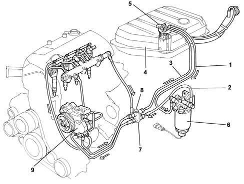
1 - Outlet pipe from tank to fuel filter.
2 - Delivery pipe from fuel filter to four-way fitting on engine.
3 - Return pipe from four-way engine fitting to tank
4 - Fuel tank.
5 - Fuel pre-supply pump submerged in tank.
6 - Fuel filter.
7 - Four-way fitting on engine.
8 - Bontaz pressure relief valve.
9 - High pressure pump (Radialjet).
Submerged pump assembly (Auxiliary) and fuel level gauge control
The assembly consists mainly of:- a roller-type fuel pump;
- a fuel level gauge;
- a fuel filter.
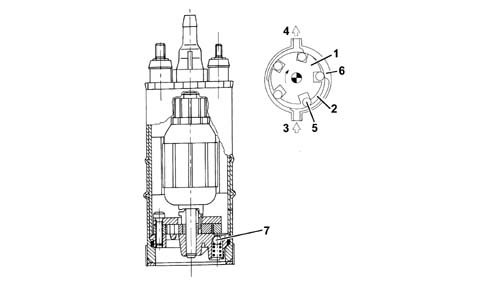
1 - Impeller.
2 - Volumes.
3 - Intake port.
4 - Outlet port.
5 - Rollers.
6 - Outer race.
7 - Pressure relief valve.
Fuel filter
The fuel filter is located in the engine bay on the driver's side and secured to the passenger compartment - engine bay bulkhead.The filter is cartridge type with a filter element. It is fitted with a fuel preheating device controlled by a thermal switch fitted to the filter. When diesel fuel temperature is lower than 6 °C, an electrical coil heats the fuel to a maximum of 15 °C before directing it to the pressure pump.A water presence sensor screwed to the base of the fuel filter cartridge also acts as a drain.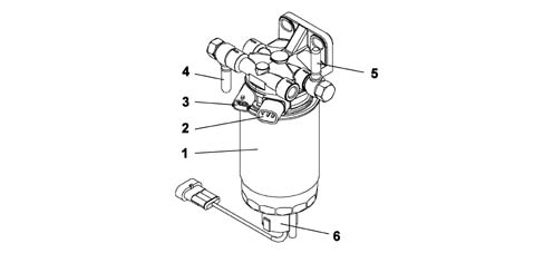
1 - Filter cartridge.
2 - Fuel preheating.
3 - Fuel temperature sensor.
4 - Fuel inlet from tank.
5 - Fuel outlet to radialjet pump.
6 - Cap with water presence sensor in filter.
High pressure pump CP3
Specifications
Pump CP3 is designed with 3 radial pistons controlled by the timing gear, without the need for timing adjustment, with a rotor feed pump applied to the rear side.Delivery pressure to the rail is modulated by the electronic control unit via the pressure regulator. The pump is lubricated and cooled by the fuel.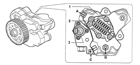
A - Fuel return
B - Fuel return
C - Fuel intake from filter
D - Fuel outlet fitting from supply pump to Rail
1 - High pressure pump
2 - Feed pump
3 - Pressure regulator (NA solenoid modulated by control unit)
Operation
Pump element (3) is forced outward by a cam on the pump shaftDuring intake, the compression chamber is supplied with fuel via port (5). The amount of fuel directed to the compression chamber is modulated by pressure regulator (7).The pressure regulator is governed by the engine control unit by means of PWM (Pulse Width Modulation) signals and reduces fuel flow in the low pressure circuit by altering the passage area.During the compression stage, the fuel reaches the pressure required to open valve (2). It is then sent to the Common Rail through outlet fitting (1).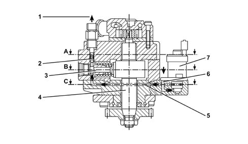
Cross section through pump
1 - Outlet fitting.
2 - Valve on outlet circuit
3 - Pump element
4 - Pump shaft
5 - Passage of fuel toward pump element
6 - Passage of fuel toward pressure regulator
7 - Pressure regulator
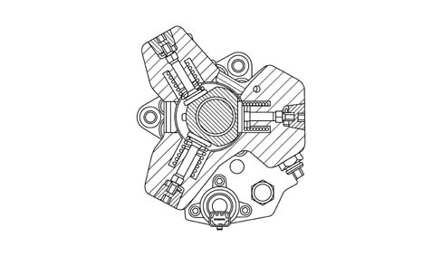
Longitudinal section through pump
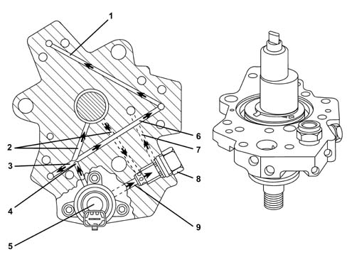
1 - Fuel inlet channel to pump elements
2 - Pump lubrication channel
3 - Fuel inlet channel to pump elements
4 - Main fuel inlet channel to pump elements
5 - Pressure regulator
6 - Fuel inlet channel to pump elements
7 - Recirculation from pressure regulator
8 - Regulator vallve on low pressure circuit (5 bars)
9 - Recirculation from intake to pressure regulator
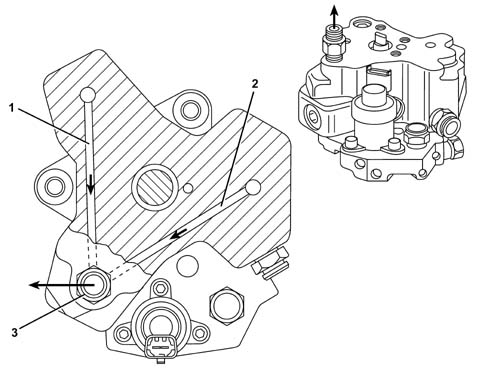
1 - Fuel outlet channel from pump elements
2 - Fuel outlet channel from pump elements
3 - Fuel outlet fitting from pump to common rail
Fuel pressure regulator
The fuel pressure regulator is fitted to the low pressure circuit of pump CP3.The pressure regulator modulates the amount of fuel sent to the high pressure circuit on the basis of commands received directly from the engine control unit.The pressure regulator consists mainly of the following components:- connector,
- case,
- solenoid,
- preload spring,
- plunger cylinder.
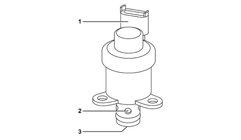
1 - Connector
2 - Fuel outlet ports
3 - Fuel inlet port
Operation
When the engine control unit governs the pressure regulator (via a PWM signal), solenoid (1) is energised and generates in turn movement of magnetic core (2).Core movement causes plunger cylinder (3) to move sideways and partially block fuel flow.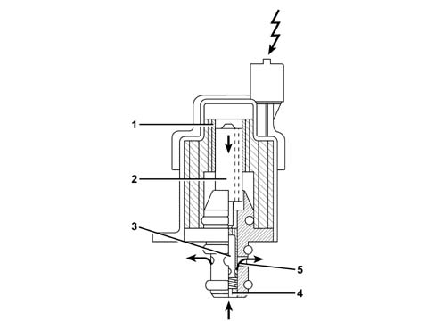
1 - Solenoid
2 - Magnetic core
3 - Plunger cylinder
4 - Fuel inlet
5 - Fuel outlet
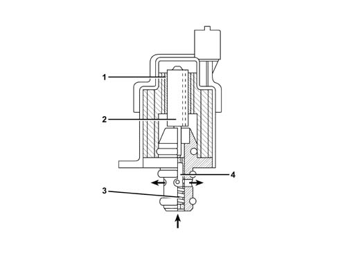
1 - Solenoid
2 - Magnetic core
3 - Preload spring
4 - Plunger cylinder
Fuel tank cap with safety valve
The following figure contains a graph showing the operation of the valve inside the fuel tank cap.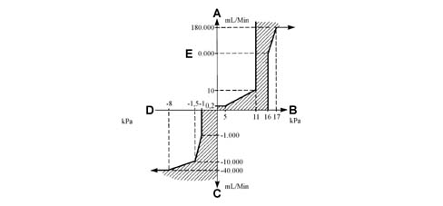
A - Air outlet from tank.
B - Tank pressure.
C - Air intake to tank.
D - Vacuum in tank
E - Ventilation not varying from plot.
- tank pressurisation;
- ventilation;
- seal in the case of roll-over.
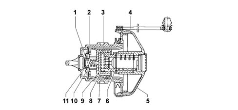
1 - Pressure spring.
2 - Pressure plate.
3 - Clutch.
4 - Cap retaining cord
5 - Cover.
6 - Fastening spring.
7 - Valve mount.
8 - Clutch spring.
9 - Cylinder mount.
10 - Vacuum plate
11 - Vacuum spring.
Delivery manifold (RAIL)
The hydraulic accumulator is fitted to the cylinder head opposite to the intake side. With a volume of 20 cm³, this damps fuel pressure fluctuations due to:- high pressure pump operation;
- injector opening.
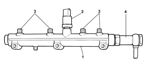
Pressure relief valve
A pressure relief valve (1750 bars) on the rail protects system components if a flow limiter cuts in.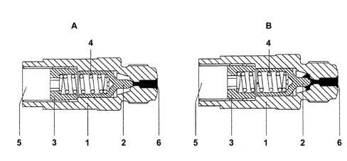
1 - Casing
2 - Piston
3 - Stop
4 - Spring
5 - Direct outlet to tank
6 - Seat on rail
A - Valve closed
B - Valve open
Safety inertia switch
The vehicle is fitted with a safety inertia switch located on the engine bay on the dashboard wall near the battery to increase vehicle occupant safety during crashes.The sensor reduces the possibility of fire (due to emerging fuel) by deactivating the axiliary pump that feeds the fuel circuit.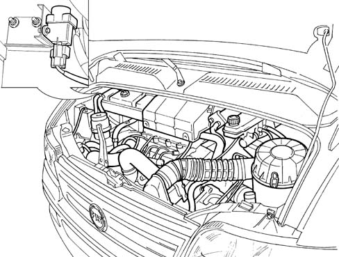
Intertia switch components
The following figure shows the inertia switch components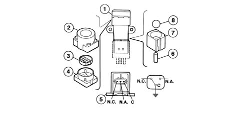
1 - Inertia switch assembly.
2 - Sheath.
3 - Button.
4 - Upper side.
5 - Engagement side.
6 - Permanent magnet.
7 - Permanent magnet seat.
8 - Steel ball.
C - Shared terminal.
N.C. - Normally closed contact.
N.O. - Normally open contact.
Engines: 2.8 JTD 8V
INTRODUCTION
In operational terms, the fuel supply circuit is divided into a low pressure circuit and a high pressure circuit.The low pressure circuit consists of the tank, auxiliary electric pump submerged in the tank, fuel cooling coil and a return manifold.The high pressure circuit consists of a radialjet pressure pump, outlet manifold and injectors.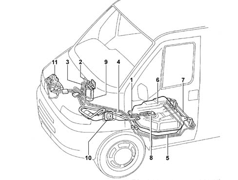
1 - Outlet pipe from tank to fuel filter.
2 - Supply pipe from fuel filter to high pressure pump.
3 - Pipe connecting fuel filter excess pressure valve to low pressure recirculation connector.
4 - Return pipe from connector to fuel cooling coil.
5 - Pipe connecting cooling coil to fuel tank.
6 - Fuel tank.
7 - Fuel cooling coil.
8 - Fuel pre-supply pump submerged in tank.
9 - Fuel filter.
10 - Fuel cap.
11 - High pressure pump (Radialjet).
Submerged pump assembly (Auxiliary) and fuel level gauge control
The assembly consists mainly of:- a roller-type fuel pump;
- a fuel level gauge;
- a fuel filter.
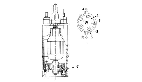
1 - Impeller.
2 - Volumes.
3 - Intake port.
4 - Outlet port.
5 - Rollers.
6 - Outer race.
7 - Pressure relief valve.
Fuel filter
The fuel filter is located in the engine bay on the driver's side and secured to the passenger compartment - engine bay bulkhead.The filter is cartridge type with a filter element. It is fitted with a fuel preheating device controlled by a thermal switch fitted to the filter. When diesel fuel temperature is lower than 6 °C, an electrical coil heats the fuel to a maximum of 15 °C before directing it to the pressure pump.A water presence sensor screwed to the base of the fuel filter cartridge also acts as a drain.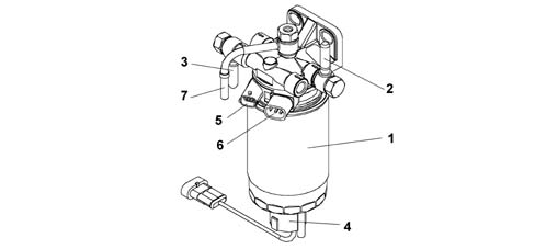
1 - Filter cartridge.
2 - Fuel inlet from tank.
3 - Fuel outlet to radialjet pump.
4 - Cap with water presence sensor in filter.
5 - Fuel temperature sensor.
6 - Fuel preheating.
7 - Pipe from high pressure pump to fuel filter.
High-pressure pump
The radial jet type pressure pump has three radial pistons (total capacity 0.657 cc) and is operated by the timing belt.Each pumping unit consists of:- a piston (5) operated by a cam (2) in one piece with the pump shaft (6);
- an intake valve (3);
- a ball delivery valve (4);
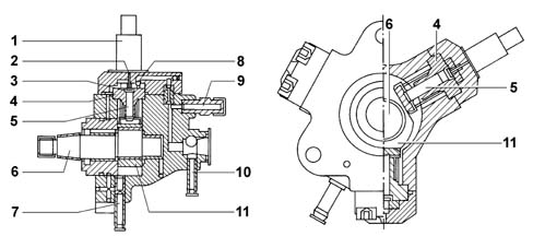
1 - 3rd pump element cut-out solenoid.
2 - Push rod.
3 - Intake valve.
4 - Cylinder.
5 - Pump.
6 - Pump shaft
7 - Inlet (low pressure, from the filter).
8 - Ball delivery valve.
9 - Supply (high pressure, rail).
10 - Supply (low pressure, recirculation).
11 - Cam.
Fuel pressure regulator
The fuel pressure sensor is fitted on the pressure pump and is operated directly by the injection control unit; it regulates the fuel supply pressure to the injectors. The pressure regulator consists mainly of the following components: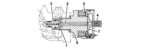
1 - Ball plunger.
2 - Pin.
3 - Valve.
4 - Preloading spring
5 - Coil.
6 - Casing
7 - Keeper.
Fuel tank cap with safety valve
The following figure contains a graph showing the operation of the valve inside the fuel tank cap.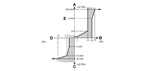
A - Air outlet from tank.
B - Tank pressure.
C - Air intake to tank.
D - Vacuum in tank.
E - Ventilation not varying from plot.
- tank pressurisation;
- ventilation;
- seal in the case of roll-over.
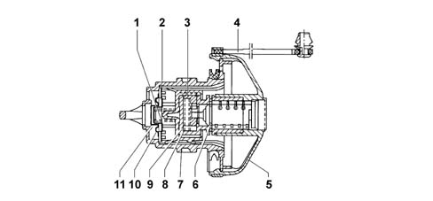
1 - Pressure spring.
2 - Pressure plate.
3 - Clutch.
4 - Cap retaining cord
5 - Cover.
6 - Fastening spring.
7 - Valve mount.
8 - Clutch spring.
9 - Cylinder mount.
10 - Vacuum plate.
11 - Vacuum spring.
Delivery manifold (rail)
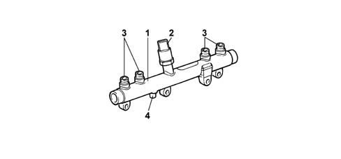
The hydraulic accumulator is fitted to the cylinder head opposite to the intake side. With a volume of around 29 cm³, this damps fuel pressure fluctuations due to:- high pressure pump operation;
- injector opening.
Safety inertia switch
The vehicle is fitted with a safety inertia switch located on the engine bay on the dashboard wall near the battery to increase vehicle occupant safety during crashes.The sensor reduces the possibility of fire (due to emerging fuel) by deactivating the axiliary pump that feeds the injection circuit.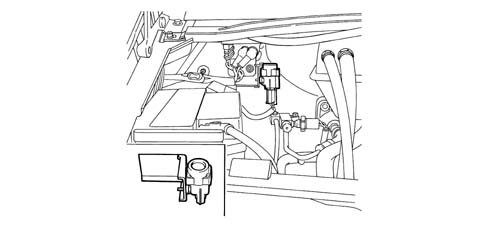
Intertia switch components
The following figure shows the inertia switch components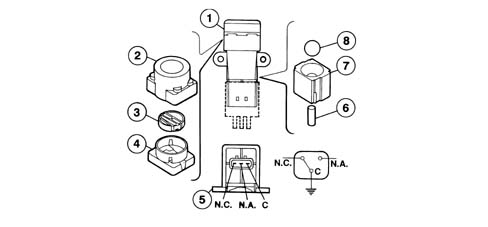
1 - Inertia switch assembly.
2 - Sheath.
3 - Button.
4 - Upper side.
5 - Engagement side.
6 - Permanent magnet.
C - Shared terminal
7 - Permanent magnet seat.
8 - Steel ball.
N.C. - Normally closed contact.
N.O. - Normally open contact.