The engine exhaust gases flow through the manifold to the turbocharger, through a pipe, to the oxidising catalytic converter and then to the silencer. Special protections limit heat radiation to the body.
EMISSION CONTROL DEVICES
Oxidising catalytic converter
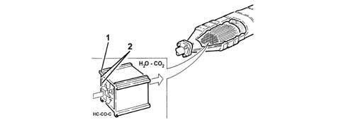
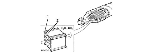
The oxidising catalytic converter is a post-treatment device for oxidizing the CO, HC and particulate so that they are converted into carbon dioxide (CO2) and water vapour (H20). The catalytic converter consists of a ceramic, honeycomb structure (1) with cells impregnated with platinum (2), a catalyst of oxidation reactions.- The exhaust gases passing through the cells heat the catalytic converter to trigger the conversion of pollutants into inert compounds. The chemical reaction involved in oxidation of CO, HC and particulate is effective at temperatures between 200 °C and 350 °C. Above 350 °C, the sulphur contained in the diesel begins to oxidise and generate sulphur dioxide and sulphuric acid.The 2.3 JTD version WITH EGR is fitted with a DEGUSSA - TECH4 catalytic converter.
Exaust Gas Recirculation (EGR) circuit
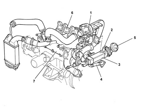
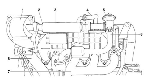
This system is used to direct a proportion of exhaust gases to the intake under certain engine service conditions. This action dilutes the fuel mixture with inert gases to lower the temperature peak in the combustion chamber. Generation of nitrogen oxides (NOX) is thus contained to bring about a 30 - 50% reduction at the exhaust.Blowby gas recirculation is permitted only at medium - low loads when the fuel-air ratio is very high and engine service is not impaired by the presence of inert gases in place of air.
1 - Throttle valve.
2 - Coolant pipe for EGR heat exchanger.
3 - Heat exchanger for EGR system.
4 - Coolant pipe for EGR heat exchanger.
5 - EGR valve.
6 - Exhaust manifold.
7 - Intake manifold.
Recirculation is controlled by the engine control unit that sends an output control signal to the modulation solenoid on the basis of signals from the accelerator pedal potentiometer, engine rpm sensor and engine coolant sensor.The modulator solenoid is connected to the atmosphere by means of a filter and directs a lower or higher vacuum from the brake servo vacuum pump to the EGR valve according to the control signal received.If the vacuum is sufficient, the EGR valve opens to bring the exhaust manifold into communication with the intake manifold.Another vacuum modulation solenoid is controlled by the engine control unit and sends a vacuum generated by the vacuum pump to the throttle actuator located on the pipe from compressor to intercooler. This throttle valve allows the exhaust gas quantity recirculated under certain conditions, e.g. idling, to be increased.
EGR valve
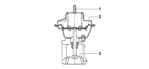
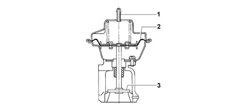
The valve is controlled by a vacuum generated by the brake servo pump and modulated by a Borg-Warner solenoid.The vacuum flows thorugh duct (1) to raise membrane (2) and connected plunger (3) to open up a cross-section of the gas passage proportional to the vacuum in the duct.An appropriate amount of combustion gas is thus recirculated to the intake manifold.
1 - Vacuum duct.
2 - Membrane.
3 - Plunger.
Proportional solenoid
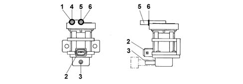
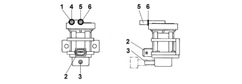
The device is connected to the pneumatic E.G.R. system by means of a vacuum intake from the brake servo vacuum pump (5), which is fitted with an output connected to Mitsubishi EGR valve (4) and atmospheric pressure intake (3). The intake draws in air from a filter with a square wave signal at a frequency of 140 Hz, voltage of 12 V and variable Duty-Cycle that generates a current from 0 to about 800 mA. Under these conditions, the maximum vacuum value is transmitted to the Mitsubishi valve.The term Duty Cycle describes the ratio betwen the time period when the signal is 12 V and total cycle period (1/140 s).Note that the modulated vacuum is not dependent on vacuum input value but only on the electric control signal Duty Cycle.The solenoid is governed directly from the injection control unit by means of a 140 ± 7 Hz frequency altenating current with a rated voltage of 12 V and intensity ranging from a minimum of 0 mA (solenoid not excited) to a maximum of 700-800 mA - when the maximum vacuum value is directed to the Pierburg valve.
1 - YELLOW identification mark.
2 - Electrical connector.
3 - Atmospheric intake.
4 - Modulated vacuum outlet to EGR valve
5 - Vacuum intake from brake servo vacuum pump.
6 - WHITE identification mark.
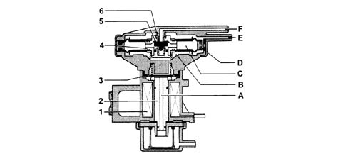
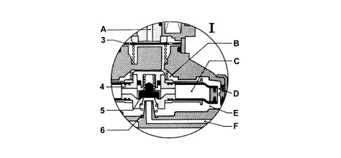
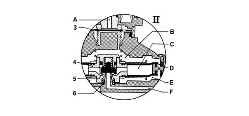
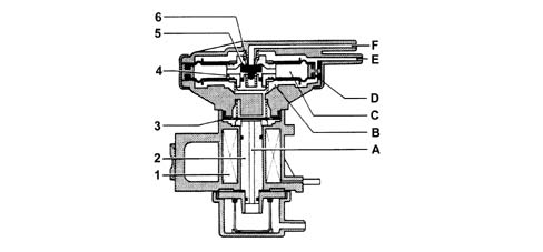
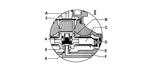
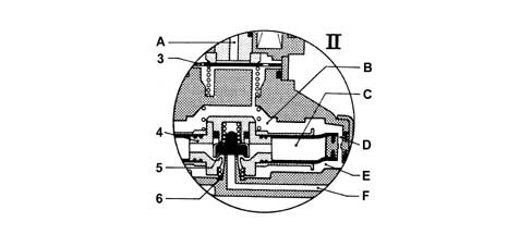
Vacuum from the brake servo vacuum pump reaches chamber (E) from duct (F) (situation I) because the force of spring (6) acts on mobile equipment (4) and branch valve (5) allows the vacuum through.The vacuum then moves on through compensation port (D) to chamber (B) and the surface of disc plunger (3).Once the forces acting on disc (3) are balanced, atmospheric pressure in duct (A) enters chamber (B) to move the mobile equipment down (situation II). The plunger of valve (5) therefore closes duct (F) and brings chamber (E) into communication with chamber (C) at atmospheric pressure to reduce the vacuum value in duct (E).The drop in the vacuum or increase in absolute pressure in chamber (E) causes the mobile equipment (4) to rise (situation I). This closes off passage (C) and returns valve (5) to the ideal state (E communicating with F) to begin the cycle again.
Engines: 2.8 JTD 8V
The engine exhaust gases flow through the manifold to the turbocharger, through a pipe, to the oxidising catalytic converter and then to the silencer. Special protections limit heat radiation to the body.
EMISSION CONTROL DEVICES
Oxidising catalytic converter
The oxidising catalytic converter is a post-treatment device for oxidizing the CO, HC and particulate so that they are converted into carbon dioxide (CO2) and water vapour (H20). The catalytic converter consists of a ceramic, honeycomb structure (1) with cells impregnated with platinum (2), a catalyst of oxidation reactions.The exhaust gases passing through the cells heat the catalyzer triggering off the conversion of the pollutants into inert compounds. The chemical reaction involved in oxidation of CO, HC and particulate is effective at temperatures between 200 °C and 350 °C. Above 350 °C, the sulphur contained in the diesel begins to oxidise and generate sulphur dioxide and sulphuric acid.The 2.8 JTD version WITH EGR is fitted with a DEGUSSA - TECH4 catalytic converter.
Exaust Gas Recirculation (EGR) circuit
This system is used to direct a proportion of exhaust gases to the intake under certain engine service conditions. This action dilutes the fuel mixture with inert gases to lower the temperature peak in the combustion chamber. Generation of nitrogen oxides (NOX) is thus contained to bring about a 30÷ 50% reduction at the exhaust.Blowby gas recirculation is permitted only at medium - low loads when the fuel-air ratio is very high and engine service is not impaired by the presence of inert gases in place of air.
1 - Heat-flange.
2 - Coolant pipe for EGR heat exchanger.
3 - Heat exchanger for EGR system.
4 - Coolant pipe for EGR heat exchanger.
5 - EGR valve.
6 - Pipe connecting exhaust manifold and EGR valve.
7 - Exhaust manifold.
8 - Intake manifold.
Recirculation is controlled by the engine control unit that sends an output control signal to the modulation solenoid on the basis of signals from the accelerator pedal potentiometer, engine rpm sensor and engine coolant sensor.The modulator solenoid is connected to the atmosphere by means of a filter and directs a lower or higher vacuum from the brake servo vacuum pump to the EGR valve according to the control signal received.If the vacuum is sufficient, the valve (4) opens to bring the exhaust manifold into communication with the intake manifold.
EGR valve
The valve is controlled by a vacuum generated by the brake servo pump and modulated by a Borg-Warner solenoid (see figure on page 36).The vacuum flows thorugh duct (1) to raise membrane (2) and connected plunger (3) to open up a cross-section of the gas passage proportional to the vacuum in the duct.An appropriate amount of combustion gas is thus recirculated to the intake manifold.
1 - Vacuum duct.
2 - Membrane.
3 - Plunger.
Proportional solenoid
The device is connected to the pneumatic E.G.R. system by means of a vacuum intake from the brake servo vacuum pump (5), which is fitted with an output connected to a Pierburg EGR valve (4) and atmospheric pressure intake (3). The intake draws in air from a filter with a square wave signal at a frequency of 140 Hz, voltage of 12 V and variable Duty-Cycle that generates a current from 0 to about 800 mA. Under these conditions, the maximum vacuum value is transmitted to the Pierburg valve.The term Duty Cycle describes the ratio betwen the time period when the signal is 12 V and total cycle period (1/140 s).Note that the modulated vacuum is not dependent on vacuum input value but only on the electric control signal Duty Cycle.The solenoid is governed directly from the injection control unit by means of a 140 ± 7 Hz frequency altenating current with a rated voltage of 12 V and intensity ranging from a minimum of 0 mA (solenoid not excited) to a maximum of 700 ÷ 800 mA - when the maximum vacuum value is directed to the Pierburg valve.
1 - YELLOW identification mark.
2 - Electrical connector.
3 - Atmospheric intake.
4 - Modulated vacuum outlet to EGR valve
5 - Vacuum intake from brake servo vacuum pump.
6 - WHITE identification mark.
Vacuum from the brake servo vacuum pump reaches chamber (E) from duct (F) (situation I) because the force of spring (6) acts on mobile equipment (4) and branch valve (5) allows the vacuum through.The vacuum then moves on through compensation port (D) to chamber (B) and the surface of disc plunger (3).Once the forces acting on disc (3) are balanced, atmospheric pressure in duct (A) enters chamber (B) to move the mobile equipment down (situation II). The plunger of valve (5) therefore closes duct (F) and brings chamber (E) into communication with chamber (C) at atmospheric pressure to reduce the vacuum value in duct (E).The drop in the vacuum or increase in absolute pressure in chamber (E) causes the mobile equipment (4) to rise (situation I). This closes off passage (C) and returns valve (5) to the ideal state (E communicating with F) to begin the cycle again.