Descriptions
BOSCH EDC ELECTRONICALLY-CONTROLLED FUEL SYSTEM
Engines: 2.0 JTD 8V
INTRODUCTION
New Ducato 2000 JTD vehicles are equipped with a 1997 cc 4 cylinder in-line turbodiesel engine with two valves per cylinder and one overhead camshaft, air turbocharging by means of a turbocharger and intercooler and electronic direct injection.The fuel system ensures the engine operates correctly and may be schematically broken down into the following circuits:- fuel supply circuit with Common Rail injection;
- air supply circuit;
- exhaust circuit;
- crankcase oil vapour recirculation circuit;
- exhaust gas recirculation circuit (EGR).
- availability of high pressure (up to 1350 bars);
- possibility of modulating these pressures (from a minimum of 150 bars to a maximum of 1350 bars) independently of engine rotation speed (rpm) and load;
- ability to work at high engine rpms (up to 6000 rpm);
- injection control precision (injection advance and duration);
- engine speed;
- engine timing;
- intake air flow;
- coolant temperature;
- air temperature;
- fuel temperature;
- fuel pressure;
- atmospheric pressure;
- intake manifold pressure;
- accelerator pedal position;
- brake and/or clutch pedal operation.
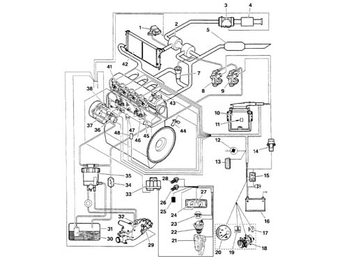
1 - Intake manifold pressure sensor;
2 - Turbocharger;
3 - Air flow meter with air temperature sensor;
4 - Air cleaner;
5 - Catalytic converter;
6 - Not connected;
7 - Exhaust gas recirculation valve (EGR).
8 - Exhaust gas recirculation regulation solenoid (EGR).
9 - Turbo pressure regulation solenoid;
10 - Engine management control unit;
11 - Atmospheric pressure sensor (built into the engine control unit);
12 - Diagnostics warning light;
13 - Centralised tester input;
14 - Inertia switch;
15 - Main relay;
16 - Battery;
17 - Electric fan;
18 - Climate control system compressor;
19 - Engine coolant temperature warning light;
20 - Engine coolant temperature gauge;
21 - Accelerator pedal position sensor;
22 - Vehicle speed sensor;
23 - Preheating warning light;
24 - Electronic rev counter;
25 - Engine immobiliser;
26 - Brake pedal switch;
27- On-board computer;
28 - Clutch pedal switch;
29 - Engine coolant temperature sensor;
30 - Filler pump (low pressure);
31 - Fuel tank;
32 - Fuel heater;
33 - Pre-postheating control unit;
34 - Fuel radiator;
35 - Fuel filter;
36 - High pressure regulator;
37 - High pressure pump;
38 - High pressure pump third piston deactivator;
39 - Damper;
40 - Not connected;
45 - Preheating spark plugs;
41 - Injectors;
42 - Air/air heat exchanger;
43 - Engine timing sensor;
44 - Engine speed sensor;
46 - Fuel manifold;
47 - Fuel high pressure sensor;
48 - Fuel temperature sensor;
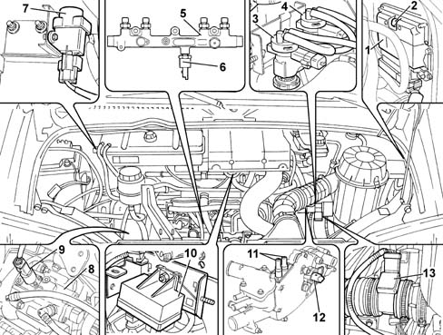
Location of main fuel system components
1 - Engine management control unit;
2 - Atmospheric pressure sensor (built into the engine control unit);
3 - Exhaust gas recirculation regulation solenoid (EGR).
4 - Turbo pressure regulation solenoid;
5 - Fuel manifold;
6 - Fuel high pressure sensor;
7 - Inertia switch;
8 - High pressure pump;
9 - High pressure pump third piston deactivator;
10 - Pre-postheating control unit;
11 - Fuel heater;
12 - Engine coolant temperature sensor;
13 - Air flow meter with air temperature sensor;
- injectors;
- turbo pressure regulation solenoids;
- high pressure circuit;
- exhaust gas recirculation regualation solenoid (EGR);
- pre/postheating control unit;
- high pressure pump third piston deactivator;
- rev counter;
- fuel comsumption gauge;
- compressor activation relay;
- radiator fan activation relay.
FUEL SYSTEM MANAGEMENT STRATEGIES
The main purpose of the management strategies is to calculate the exact amount of fuel to be injected into the cylinders (injection time). The associated timing (injection advance) and precision are set to ensure the best possible engine performance in terms of power, fuel consumption, fume emissions and vehicle handling.Injection time is calculated on the basis of the following main parameters:- amount of fuel to be injected;
- pressure available in the high pressure fuel manifold;
- engine speed.
- a) preinjection
- b) main injection
- engine speed greater than 3200 rpm;
- insufficient high pressure;
- degasification of high pressure fuel manifold (start-up stage);
- fuel supply lower than a minimum threshold.
- excessive pressure in the fuel manifold (pressure greater than 1500 bars);
- insufficient pressure in the fuel manifold (pressure lower than 120 bars);
- maximum engine speed reached.
- basic map;
- accelerator pedal map;
- full load curve;
- turbo pressure map;
- exhaust gas recirculation map;
- fume limitation map;
- high fuel pressure map.
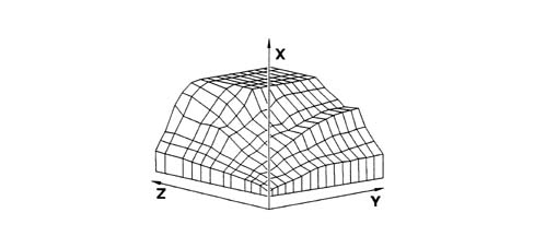
- X: high fuel pressure;
- Y: engine speed;
- Z: amount of fuel to be injected.
- to prevent great fluctuations in fuel supply (driving comfort);
- to achieve a smooth delivery curve (driving comfort).
- controls turbocharging on the basis of the amount of fuel to be injected.
- allows the exhaust gas recirculation percentage to be calculated with extreme accuracy on the basis of the following parameters: amount of fuel to be injected, atmospheric pressure, amount of air entering the engine (measured).
- allows fuel high pressure value to be calculated on the basis of the amount of fuel to be injected.
- control of amount of fuel injected;
- injetion advance control;
- injection pressure control;
- auxiliary fuel pump check;
- injection control during over-run (cut-off);
- idle speed control;
- maximum speed limit control;
- maximum torque limit control;
- fuel temperature control;
- turbo pressure control;
- control of engine cooling fan;
- control of glow plugs;
- exhaust fume control;
- exhaust gas recirculation control (E.G.R.);
- climate control system activation control;
- engine immobiliser function control;
- self-diagnostics.
Control of amount of fuel injected
The control unit manages the fuel pressure regulator and injectors on the basis of signals from the accelerator pedal potentiometer, debimeter and rpm sensor.Injection timing and thus injection sequence are determined upon engine start-up using signals from the engine rpm sensor and timing sensor (synchronisation stage). Injection timing is then implemented using the engine rpm sensor signal alone and considering a 1 -3 -4 -2 injection sequence.The control unit inhibits injection in the following cases:- Fuel pressure value greater than 1500 bar;
- Fuel pressure value lower than 120 bar;
- engine speed greater than 6000 rpm.
Injection advance control
The electronic control unit determines injection advance mainly on the basis of the amount of fuel to be injected.Injection advance is then corrected on the basis of engine coolant temperature and speed in order to compensate for the increase in ignition delay due to low temperatures present in the combustion chambers during warm-up.Injection pressure control
This control is particularly important because injection pressure influences the following parameters:- amount of fuel taken into the cylinders for the same injection time duration;
- nebulisation of fuel injected;
- jet penetration;
- delay between electric injector control and the effective start of fuel injection.
Auxiliary fuel pump check
The auxiliary fuel pump submerged in the tank is supplied by the injection control unit via a relay when the ignition key is turned to ON.The pump supply is inhibited under the following circumstances:- after the ignition key has been turned ON for a certain time but the engine is not running;
- if the inertia switch has gone off;
Injection control during over-run (cut-off)
The fuel cut-off strategy is implemented when the injection control unit receives a signal to indicate that the accelerator pedal is released from the relevant potentiometer.Under these conditions, the control unit cuts off the fuel supply to the injectors and restores it before idle speed is reached.Idle speed control
The injection control unit controls the pressure regulator and alters injector opening times on the basis of signals from the engine rpm sensor and coolant temperature sensor to keep idle speed stable.Under certain conditions, the control unit also considers battery voltage when controlling idle speed.Maximum speed limit control
The injection control unit limits maximum speed on the basis of rpm by means of two actions:- as maximum speed approaches, it reduces the amount of fuel injected and reduces line pressure;
- injector operation is inhibited at speeds over 6000 rpm.
Maximum torque limit control
The injection control unit calculates limit torque and maximum permitted fume index parameters according to rpm. The calculations are based on predefined maps stored in its memory.The control unit then corrects the above parameters using engine coolant and vehicle speed data and uses the resulting values to modulate the amount of fuel to be injected by adjusting the pressure regulator and injectors.Fuel temperature control
The injection control unit is kept constantly informed on fuel temperature by a sensor in the return manifold.If fuel temperature exceeds a certain level (about 110°C), the control unit reduces line pressure by adjusting the pressure regulator and leaving the injection times the same.Engine coolant temperature control
The injection control unit is constantly informed of engine coolant temperature by means of a sensor on the thermostat.If engine coolant temperature exceeds certain levels, the control unit takes the following actions:- reduces fuel quantity by adjusting the pressure regulator or injectors (power reduction);
- drives the engine radiator cooling fan.
Heater plugs check
The injection control unit controls operation of the glow plug control unit to bring temperature in the combustion chambers up levels sufficient to facilitate fuel self-ignition and thus make ignition easier.The injection control unit controls operation of the glow plug preheating control unit for a certain time both before (preheating) and after (postheating) engine start-up and also controls activation of the relevant warning light on the control panel.The glow plug preheating, postheating and activation times all vary on the basis of engine coolant temperature.Exhaust fume control
By means of this function, the injection control unit limits any exhaust fumes that could occur during fast acceleration.To meet this requirement, the control unit processes signals supplied by the accelerator pedal potentiometer, rpm sensor and intake air quantity sensor (debimeter) and controls the fuel pressure regulator and injectors to modulate the amount of fuel to be injected.Exhaust gas recirculation control
The injection control unit computes EGR solenoid operation times on the basis of signals supplied by the rpm, intake air quantity, coolant temperature and accelerator pedal position sensors to obtain partial exhaust gas recirculation only under certain engine operation conditions.Control of air conditioning system activation
The injection control unit manages the air conditioner system compressor electromagnetic coupling in accordance with a strategy designed to avoid operating conditions that would impair engine performance.When the compressor is activated, the engine control unit increases the amount of fuel at idle speed to adjust the engine to the higher power requirement and cut off power supply to the compressor under conditions of:- high power demand from the engine (fast acceleration);
- engine coolant overheating.
Engine immobiliser function control
The system is equipped with an engine immobiliser. This function is executed by a specific control unit (Fiat CODE) able to communicate with the engine control unit and an electronic key with a transmitter that sends out a recognition code. Whenever the key is turned OFF, the Fiat CODE system fully deactivates the injection control unit.When the key is turned ON, the following operations take place in sequence:- 1 - the engine control unit (with the secret code in its memory) sends the Fiat CODE control unit a request to send a secret code to deactivate the function lock;
- 2 - the Fiat CODE control unit responds by sending back the secret code only once it has received, in turn, a recognition code sent by the ignition key;
- 3 - secret code recognition allows engine control unit lock deactivation and resumption of normal operation.
DIAGNOSTICS
Diagnosis
The injection system can be fully tested by connecting an appropriate tester to the tester input.Fault display (self-diagnostics)
The engine diagnostics warning light comes on if a fault is present between the elements or the following information:- voltage to condenser no. 1 (injector control stage in engine management control unit);
- voltage to condenser no. 2 (injector control stage in engine management control unit);
- fuel high pressure sensor;
- pressure control circuit in fuel manifold;
- accelerator pedal sensor (stage no. 1);
- accelerator pedal sensor (stage no. 2);
- turbo pressure sensor;
- air flow meter with air temperature sensor;
- supply to sensors no. 1;
- supply to sensors no. 2;
- exhaust gas recirculation function (regulation.);
- turbo pressure regulation solenoid;
- high pressure circuit;
- injector fault (1 to 4).
Reduced operating modes (recovery)
The injection system manages the following reduced modes:- a) - operating mode with reduced fuel flow; engine rpm cannot exceed 3200 rpm under any circumstances.
- b) - a mode that stops the engine immediately.
- fuel high pressure sensor;
- pressure control circuit in fuel manifold;
- accelerator pedal sensor (stage no. 1);
- accelerator pedal sensor (stage no. 2);
- intake manifold pressure sensor;
- air flow meter with air temperature sensor;
- vehicle speed sensor;
- exhaust gas recirculation function (regulation.);
- exhaust gas recirculation regualation solenoid (EGR);
- high pressure circuit;
- EPROM in engine managment unit;
- engine speed sensor;
- engine timing sensor;
- voltage to condenser no. 1 (injector control stage in engine management control unit);
- voltage to condenser no. 2 (injector control stage in engine management control unit);
- pressure control circuit in fuel manifold;
- injector fault (1 to 4).
- climate control compressor cut-off, if a fault is detected in the fan control relay coils;
- deactivation of the third high pressure pump piston, if fuel pressure exceeds 106°C.
BOSCH EDC 15C7 ENGINE CONTROL UNIT
The EDC 15C7 processes signals from the sensors by applying software algorithms and controls actuators (particularly the injectors and pressure regulator) to achieve the most effective possible engine operation.The control unit is flash E.P.R.O.M. type and can be reprogrammed externally without the need to adjust the hardware.The engine control unit contains a built-in atmospheric pressure sensor and is connected to the wiring by means of 2 connectors that provide a total of 121 pins.Identification of EDC 15C7 engine control unit connections
The currently available versions is: 2.3 JTD engine with EGRPin Out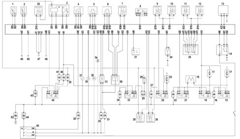
Diagram showing injection system with EGR
1 - Fuel temperature sensor;
2 - Engine coolant temperature sensor;
3 - Air flow meter (debimeter);
4 - Fuel pressure sensor;
5 - Engine rpm sensor;
6 - Timing sensor;
7 - Fuel pressure regulator;
8 - Fuel filter heater relay;
9 - Cylinder no. 1 injector;
10 - Cylinder no. 2 injector;
11 - Cylinder no. 3 injector;
12 - Cylinder no. 4 injector;
13 - Glow plug control unit;
14 - 4 stage pressure switch;
15 - Engine cooling relay (high speed);
16 - 40 A fuse;
17 - Engine cooling fan;
18 - Engine cooling relay (high speed);
19 - Resistor;
20 - Potentiometer on accelerator pedal;
21 - Engine cooling relay (low speed;
22 - 40 A fuse;
23 - Compressor;
24 - Sensor on clutch pedal;
25 - Compressor control relay;
26 - Throttle solenoid;
27 - 7.5 A fuse;
28 - Inertia switch;
29 - Electric pump submerged in tank;
30 - EGR solenoid;
31 - Pulse generator;
32 - Relay controlling electric pump submerged in tank;
33 - Vehicle brake light control;
34 - 15 A fuse;
35 - 7.5 A fuse;
36 - Preheating warning light;
37 - Injection system failure warning light;
38 - 7.5 A fuse;
39 - 15 A fuse;
40 - 10 A fuse;
41 - 20 A fuse;
42 - Main relay;
43 - 7.5 A fuse;
44 - 20 A fuse;
45 - Ignition switch;
46 - Tester input;
47 - Chassis earth;
48 - Fiat CODE control unit;
49 - Signal for rev counter on instrument panel;
50 - Cruise control
51 - 7.5 A fuse;
52 - Cruise Control activation warning light;
53 - 150 A fuse;
54 - Maximum engine coolant temperature warning light;
55 - Shut-off solenoid+.
ENGINE SPEED SENSOR
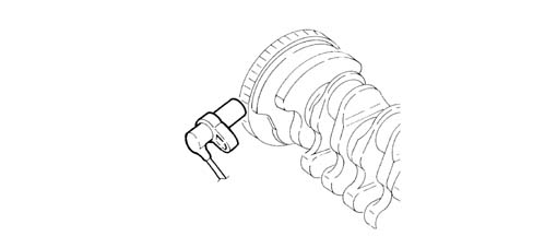
The rpm sensor is fitted on the clutch bell housing and faces a phonic wheel on the flywheel.
Function
The injection control unit uses a signal from the rpm sensor to determine crankshaft speed and angular position.Description
The sensor is inductive type, i.e. it uses changes in the magnetic field generated by the phonic wheel teeth (60-2 teeth) passing in front of the sensor element.The changeover from full to empty determined by the presence or absence of a gap brings about a magnetic flux change sufficient to generate an induced alternating voltage proportional to the number of holes on the phonic wheel.Rpm sensor peak output voltage depends, all else being equal, on the distance between the sensor and the phonic wheel teeth.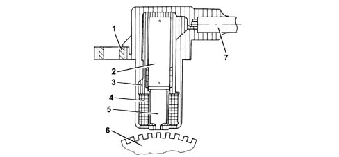
1 - Steel bush;
2 - Permanent magnet;
3 - Sensor case;
4 - Winding;
5 - Core;
6 - Phonic wheel;
7 - Electrical connection;
Winding resistance
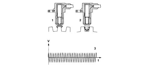
The winding resistance is 50 Ohms with a variation of ± 10
1 - Maximum magnetic flux;
2 - Minimum magnetic flux;
3 - Induced alternating voltage;
ENGINE TIMING SENSOR (CAMSHAFT POSITION)
Function
synchronise fuel injections in relation to piston position;recognise top dead centres.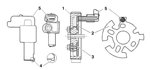
1 - camshaft pulley;
2 - phonic wheel
3 - camshaft hub;
4 - plastic pin;
5 - timing sensor.
Description
This Hall-effect sensor is installed on the cylinder head, where it faces the camshaft hub.A set of openings on the hub allows the timing sensor to detect engine timing position and notify the engine control unit accordingly.Operation
A current-carrying semiconductor layer immersed in a normal magnetic field (force lines at right angles to current direction) generates a potential difference known as a Hall voltage at its terminals.If current intensity remains constant, the generated voltage depends on magnetic field intensity alone. Periodic changes in magnetic field intensity are sufficient to generate a modulated electrical signal with frequency proportional to the speed of magnetic field change.This change is achieved by making a magnetic ring (internal part of pulley) with an opening pass the sensor.As it moves, the metal part of the ring covers the sensor to block the magnetic field and thus generate a low ouput signal. Conversely, the sensor generates a high signal when the opening is over the sensor and a magnetic field is present.ENGINE COOLANT TEMPERATURE SENSOR
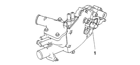
Engine coolant temperature sensor.
1 - Coolant temperature sensor
Function
The sensor provides the control unit with information about coolant temperature.According to the information received, the engine control unit:- regulates preheating time;
- regulates postheating time;
- regulates the start-up flow;
- regulates idle speed;
- authorises exhaust gas recirculation circuit (EGR);
- regulates fuel flow;
- limits the injected flow if coolant temperature becomes critical (antiboil function);
- controls the fans;
- controls the instrument panel gauge and warning light.
Description
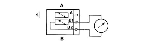
The sensor is installed on the thermostat. It consists of a brass case that protects the actual resistance elements, which take the form of two NTC (Negative Temperature Coefficient) thermistors - so-called because their electrical resistance falls as temperature increases).The two thermistors are separate and provide temperature information to the instrument panel (A) and engine management unit (B) respectively.Electrical properties:- B1 - B2: resistance at 20°C = 6200 Ohm;
- A - earth: resistance at 30°C = 1925 Ohm;
AIR TEMPERATURE SENSOR
Function
The air temperature probe provides the computer with information on intake air temperature.According to the information received, the engine control unit computes environmental air density.Description
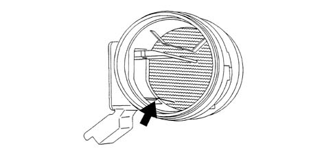
The sensor (arrowed) is built into the air flow meter.It consists of a Negative Temperature Coefficient (NTC) resistance similar in design to the coolant temperature sensor (see).Electrical properties:- resistance at 25°C = 3200 Ohm;
FUEL TEMPERATURE SENSOR
Function
The sensor measures fuel temperature. According to the information received, the engine control unit:- regulates fuel flow;
- computes fuel density.
Description
The sensor is positioned on the fuel return circuit in the tank.It consists of a Negative Temperature Coefficient (NTC) resistance similar in design to the coolant temperature sensor (see).Electrical properties:- resistance at 25°C = 2400Ohm;
- resistance at 80°C = 270 Ohm;
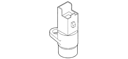
FUEL HIGH PRESSURE SENSOR
Function
The sensor measures the high pressure value in the fuel manifold. According to the information received, the engine control unit:- determines the amount of fuel to be injected;
- regulates high fuel pressure in the fuel manifold.
Description
The sensor is located on the fuel manifold and is piezoelectric type. It supplies a voltage proportional to the pressure of fuel in the fuel manifold.Electrical properties:- pressure of 100 bars: voltage = 0.5 Volts;
- pressure of 300 bars: voltage = 1.3 Volts;
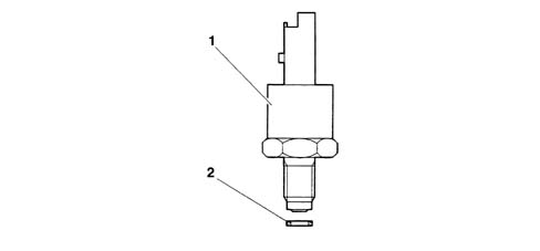
1 - Fuel high pressure sensor;
2 - Steel gasket.
VEHICLE SPEED SENSOR
Function
The sensor provides the engine management unit with information on vehicle speed. According to the information received, the engine control unit:- calculates vehicle speed (vehicle at a standstill or moving);
- determines the gear ratio engaged;
- improves idle speed with the vehicle in motion.
Description
The sensor is installed on the gearbox. It is Hall effect type and similar in design to the engine timing sensor (see).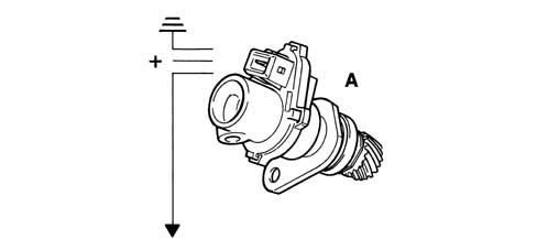
ATMOSPHERIC PRESSURE SENSOR
Function
The sensor measures atmospheric pressure. According to the information received, the engine control unit:- determines air density;
- turns off recirculation when the vehicle is at high altitude.
Description
Atmospheric pressure sensor (1) is built into the engine control unit.It is piezoelectric type and supplies a voltage proportional to atmospheric pressure.
INTAKE MANIFOLD PRESSURE SENSOR
Function
The sensor is used to determine air pressure in the intake manifold. According to the information received, the engine control unit:- modulates turbo pressure;
- modulates fuel pressure;
- regulates fuel flow.
Description
The sensor is connected to the intake air circuit at the level of the air/air heat exchanger.It is piezoelectric type and supplies a voltage proportional to air pressure in the intake manifold.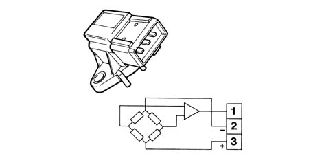
ACCELERATOR PEDAL POTENTIOMETER
Accelerator pedal position is converted into an electrical voltage signal and sent to the engine control unit by a potentiometer on the pedal unit assembly.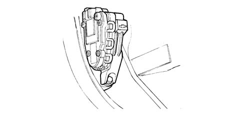
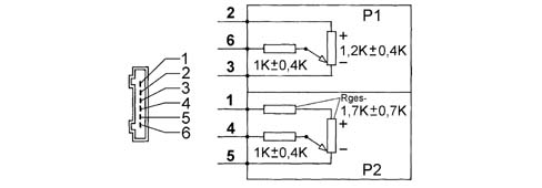
1 - 5V positive;
2 - 5V positive;
3 - Negative;
4 - Analogue signal;
5 - Negative;
6 - Analogue signal.
Accelerator pedal operation check
Connector the tester station (EXAMINER or SDC) to the input in the passenger compartment (facia junction unit).Move the accelerator pedal to the end of its travel (fully depressed).Record the accelerator pedal potentiometer output voltage.If the value measured is not within the range of 3.5 - 4.4 Volts, replace the pedal complete with potentiometer.Disconnect the tester station jack from the input in the passenger compartment (facia junction unit).BRAKE PEDAL SWITCH
Switch (1) on the brake pedal controls the vehicle brake lights. The same switch sends a signal to pin A59 of the engine control unit.The control unit uses the "brake pedal depressed" signal to:- detect a situation of deceleration;
- check the veracity of the accelerator potentiometer output signal.
CLUTCH PEDAL SWITCH
Switch (2) on the clutch pedal is connected to pin A61 of the engine control unit. The engine control unit uses the "clutch pedal operated" signal to distinguish between gear engaged and gear change conditions.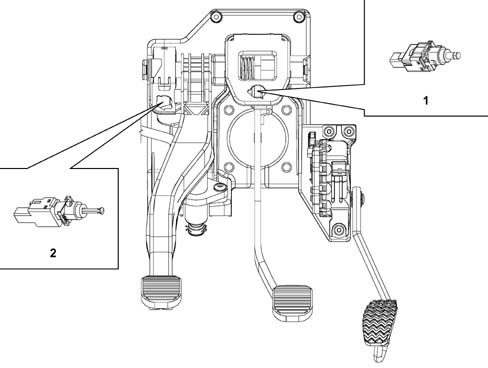
PRE-POSTHEATING CONTROL UNIT
Function
The control unit supplies electrical power to the glow plugs when controlled by the engine management unit.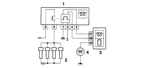
1 - pre-postheating control unit;
2 - glow plugs;
3 - engine management control unit;
4 - preheating warning light;
| Engine coolant temperature (°C ) | Pre-heating time (seconds) |
|---|---|
| -30° | 16 seconds |
| -10° | 5 seconds |
| 0° | 0.5 seconds |
| 10° | 0.25 seconds |
| 18° | 0 seconds |
| 40° | 0 seconds |
- coolant temperature less than 20°C;
- engine running at more than 700 rpm for more than 0.2 seconds.
HEATER PLUGS
Function
The glow plugs allow temperature in the combustion chambers to increase quickly during start-up.Description
The glow plugs consist of an electrical coil covered by a protective metal case.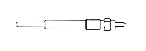
| Engine coolant temperature (°C) | Pre-heating time (seconds) |
|---|---|
| -30° | 180 |
| -10° | 180 |
| 0° | 60 |
| 10° | 60 |
| 18° | 30 |
| 40° | 0 |
SAFETY INERTIA SWITCH
The vehicle is fitted with an inertia switch located in the engine bay to increase the degree of vehicle occupant safety in the case of impact.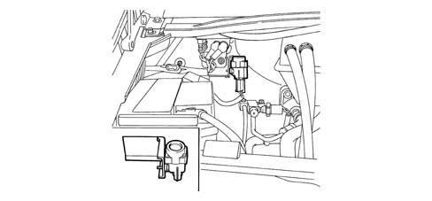
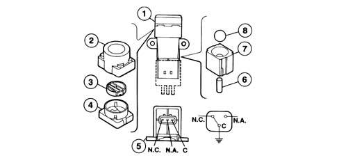
1 - Inertia sensor assembly;
2 - Sheath;
3 - Button;
4 - Upper side;
5 - Engagement side;
6 - Permanent magnet;
7 - Permanent magnet seat;
8 - Steel ball;
C - Shared terminal;
N.C. - Normally closed contact;
N.O. - Normally open contact;
FUEL FEED CIRCUIT
In operational terms, the fuel supply circuit is divided into a low pressure circuit and a high pressure circuit.The low pressure circuit consists of the tank, multifunction valve, auxiliary electric pump submerged in the tank and a return manifold.The high pressure circuit consists of a high pressure pump, outlet manifold and injectors.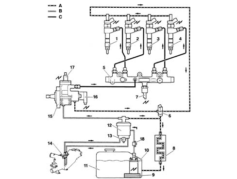
A - return circuit to tank;
B - low fuel pressure circuit;
C - high fuel pressure sensor;
1 - Injector;
2 - Injector;
3 - Injector;
4 - Injector;
5 - high fuel pressure manifold;
6 - fuel temperature sensor;
7 - high fuel pressure sensor;
8 - fuel radiator;
9 - fuel prefilter;
10 - filler pump (low pressure);
11 - fuel tank;
12 - fuel filter + water decanter + low pressure circuit pressure regulator;
13 - water bleed screw;
14 - fuel heater;
15 - high fuel pressure pump;
16 - high fuel pressure regulator on high pressure pump;
17 - high pressure pump third piston deactivator;
18 - damper.
CRADLE ASSEMBLY WITH SUBMERGED PUMP (FILLER)
The assembly consists mainly of:- a roller-type fuel pump;
- a fuel level gauge;
- a built-in fuel filter.
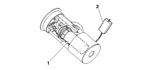
1 - filler pump (low pressure) with filter;
2 - fuel level gauge float.
Function
The filler pump:- supplies the high pressure pump with fuel;
- provides the necessary pressure to the low pressure circuit.
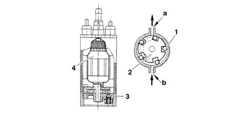
a - fuel outlet;
b - fuel inlet;
1 - rollers;
2 - impeller;
3 - safety valve;
4 - direct current motor.
Description
The electric pump submerged in the fuel is volumetric roller type with brush motor and permanent magnet excitation.Impeller (2) is turned by the electric motor to create volumes that migrate from intake port (b) to outlet port (a).These volumes are delimited by rollers (1) that adhere to pump outer race (6) during motor rotation.The electric pump is fitted with two valves:- a check valve to prevent the fuel circuit emptying (with the pump off);
- a second pressure relief valve (3) to bypass the outlet to the inlet when the pressure exceeds 7 bars.
- due to contact activation for a period of 2 to 3 seconds;
- with the engine running.
FUEL HEATER
Function
The fuel heater heats the fuel to service temperature.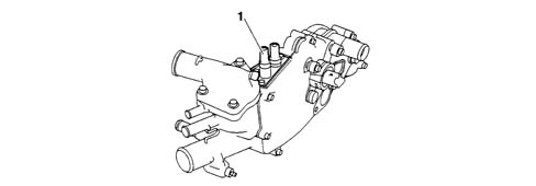
Description
The fuel heater heats fuel directed from the thermostat element (fuel filter).It takes the form of pipe (1) in contact with the coolant and is located in the thermostat casing.FUEL FILTER AND THERMOSTAT ELEMENT
This consists of three built-in elements:- fuel filter;
- low pressure regulator;
- thermostat element.
Function
fuel filtering (filter threshold 5 microns);water decanting;control of fuel heating (thermostat element);control of low pressure fuel circuit (low pressure regulator built-in).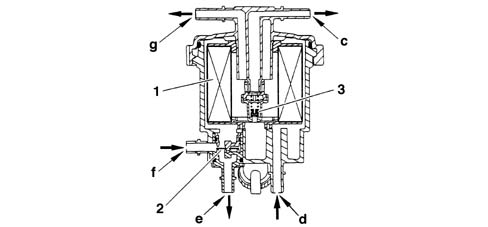
1 - filter element;
2 - thermostat element;
3 - low pressure regulator;
c - fuel return to tank;
d - heated fuel return from thermostat;
e - fuel outlet to thermostat;
f - fuel inlet;
g - fuel outlet to high pressure pump.
- replacement frequency: every 60,000 Km;
- bleed: every 20,000 Km;
Description of low pressure regulator
The low pressure regulator controls fuel pressure in the low pressure circuit.Circuit pressure: = 2.5 bar.Thermostat element description
When cold, the thermostat element directs part of the fuel toward the fuel heater.When warm, the thermostat element prevents fuel heating.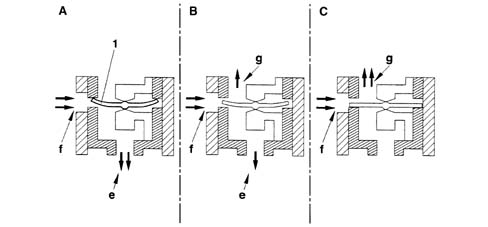
e - fuel outlet (to coolant outlet casing);
f - fuel inlet;
g - fuel outlet (to filter element);
1 - thermostat element.
- the thermostat element is raised from its seat;
- the direct passage to the filter is closed;
- fuel is heated by contact with the water outlet casing.
- the thermostat element is partly raised from its seat;
- part of the fuel is heated;
- the thermostat element rests on its seat;
- fuel flows directly toward the filter element.
FUEL RADIATOR
Function
The high pressure pump compresses fuel from the filler pump to increase the fuel temperature.The fuel radiator cools the fuel as it returns to the tank.Description
The fuel radiator is secured beneath the body. It consists of a steel coil that promotes heat exchange between fuel and air.FUEL HIGH PRESSURE PUMP
Function
the high pressure pump:- provides high fuel pressure;
- supplies the injectors via the fuel manifold.
Description
The high pressure pump receives fuel at low pressure from the filler pump and is driven by the timing belt (operating ratio 1:0.5).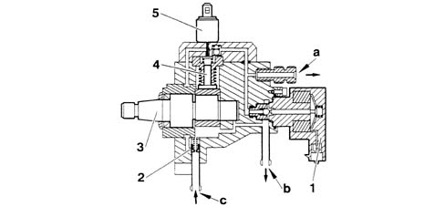
a - high pressure outlet (to fuel manifold);
b - fuel return to tank;
c - fuel inlet (from filler pump);
1 - high pressure regulator;
2 - lubrication valve;
3 - pump camshaft;
4 - piston;
5 - high pressure pump third piston deactivator.
High pressure generation
The high pressure pump shaft is fitted with a cam. The pistons are suppiled with fuel via a low pressure circuit inside the high pressure pump.Fuel is taken up by the piston during the intake stage. It is then compressed by the piston and directed via a delivery valve to the fuel manifold at a pressure level modulated by by the pressure regulator.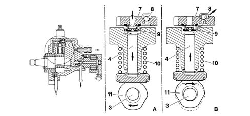
3 - Pump camshaft;
4 - High pressure piston;
7 - Fuel intake valve;
8 - Ball delivery valve;
9 - Intake valve return spring;
10 - High pressure piston return spring;
11 - Drive cam.
- the filler pump supplies fuel via intake valve (7);
- the return spring pushes the piston against the cam;
- the piston creates a vacuum in the chamber.
- after bottom dead centre;
- the fuel pressure drop brings about intake valve closure (about 1 bar);
- fuel is blocked inside the chamber;
- the high pressure pump cam pushes the piston;
- fuel pressure increases;
- fuel is directed to the delivery valve;
- delivery valve (8) opens;
- After top dead centre, the delivery valve closes due to the pressure drop.
Lubrication valve description
Lubrication valve (2) ensures high pressure pump lubrication if turbo pressure is too low. It takes up different positions according to the difference between filling pressure and pressure in the return circuit to the fuel tank.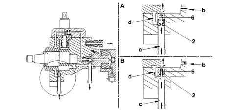
A - Pressure below 0.8 bar;
B - pressure greater than 0.8 bar;
b - fuel return to tank;
e - fuel inlet (from filler pump);
d - to high pressure stage;
2 - lubrication valve;
6 - return springs.
- the fuel pressure is insufficient to press valve (2);
- fuel flows through the valve via a calibrated hole;
- the fuel allows lubrication and cooling of the high pressure pump.
- the fuel pushes valve (2);
- part of the fuel flows into the valve through the calibrated hole;
- most of the fuel is directed to the high pressure stage of the high pressure pump.
HIGH PRESSURE PUMP THIRD PISTON DEACTIVATOR
Function
The high pressure pump third piston deactivator:- decreases power uptake by the high pressure pump if the engine is used at low load;
- quickly lowers the high pressure in the case of a fault.
Description
Components of the high pressure pump third piston deactivator:- an electromagnet;
- a push-rod that moves under the action of the magnetic field set up by the electromagnet.
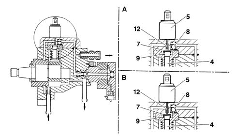
4 - high pressure piston;
5 - high pressure pump third piston deactivator;
7 - fuel intake valve;
8 - ball delivery valve;
9 - intake valve return spring;
12 - push-rod.
- fuel intake valve (7) is locked in its seat by spring (9);
- the cylinder is closed;
- the pump shaft cam action sets up pressure;
- the fuel pressure allows delivery valve (8) to rise;
- the fuel is directed toward the pump high pressure outlet.
- push-rod (12) lifts intake valve (7) from its seat;
- the cylinder is open: no pressure set up;
- fuel is directed toward the low pressure section of the high pressure pump.
Operating strategy:
The pump works using 3 pistons:- at idle speed:
- from 2/3 of fuel load to full load
- outside idle speed
- below 2/3 of full engine load.
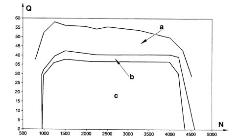
a - use of 3 pistons;
b - use of 2 or 3 pistons (hysteresis);
c - use of 2 pistons;
N - engine speed (rpm);
Q - injected fuel flow (litres).
HIGH PRESSURE REGULATOR
Function
The high pressure regulator modulates fuel pressure at the high pressure pump outlet.Description
The high pressure regulator includes 2 pressure control circuits:- an electric circuit that acts directly on the high fuel pressure that controls the high pressure regulator electromagnet (engine management control unit);
- a mechanical circuit that ensures a minimum pressure and damps pressure pulses;
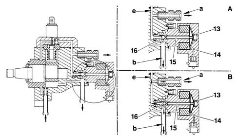
A - high pressure regulator not supplied with power;
B - high pressure regulator supplied with power;
a - high pressure fuel outlet (to fuel manifold);
b - fuel return to tank;
e - high fuel pressure circuit;
13 - spring;
14 - electrical coil;
15 - magnetic core;
16 - ball.
Mechanical control
The high pressure circuit undergoes pressure changes.Fuel pressure increases when a pump piston is pressed and decreases when an injector is opened.The ball moves to damp pressure changes.Electrical control
1 When the high pressure regulator is not supplied with power:- the high fuel pressure counters the mechanical action of spring (13);
- the regulator opens for a high pressure greater than spring load (= 100 bars);
- fuel released by the high pressure regulator returns to the tank through the outlet.
- the engine management unit supplies the high pressure regulator with a duty-cycle;
- the high pressure regulator coil drives the magnetic core (magnetic force);
- the effort applied to the ball is the sum of the force of spring (13) and the magnetic force of the core;
- the high pressure regulator setting increases.
- the engine management unit reduces the duty-cycle that supplies the high pressure regulator coil;
- the high pressure regulator coil drives the magnetic core (magnetic force);
- the effort applied to the ball decreases;
- the high pressure regulator setting decreases.
Electrical properties
Variable DC (Duty Cycle) voltage control:- maximum voltage (maximum DC) = maximum pressure;
- minimum voltage (minimum DC) = minimum pressure.
FUEL MANIFOLD (RAIL)
The fuel manifold is made out of tooled steel and located between the high pressure pump and injectors on the cylinder head.Function
The fuel manifold (rail):- joins the components of the high pressure circuit;
- stores the amount of fuel required for engine operation;
- decreases pulses determined by injections.
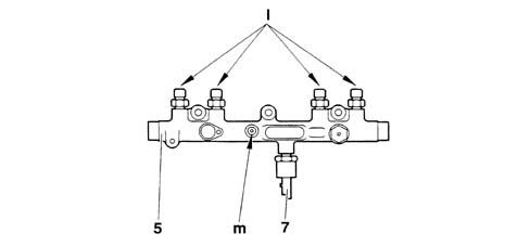
5 - high fuel pressure manifold;
7 - high pressure sensor;
1 - output to injectors;
m - high pressure supply.
INJECTORS
Function
The injectors inject the amount of fuel required to operate the engine.Description
From a mechanical viewpoint, the injector does not differ essentially from the conventional injectors used in mechanical injection diesel engines.The control solenoid is located in the upper part of the injector and secured to the injector case by nut (33).The injectors incorporate 5 holes that improve the air/fuel mixture.The amount of fuel injected depends on the following parameters:- electrical command duration;
- injector opening speed;
- injector hydraulic output (hole number and diameter);
- fuel pressure in the fuel manifold (rail).
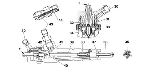
f - fuel return to tank;
30 - electrical connector;
31 - electrical control solenoid;
32 - control solenoid spring;
33 - nut;
34 - control solenoid pintle;
35 - injector tip;
36 - injector pintle (5-hole nozzle);
37 - pressure chamber;
38 - injector spring;
39 - control piston;
40 - control chamber;
41 - supply nozzle;
42 - fuel return circuit nozzle;
43 - high pressure input connector;
44 - multilayer filter built into connector (43).
Principle of injector operation
The fuel pressures used in the direct injection system obviate direct electrical control of the injectors. Injector opening is therefore achieved by exploiting the pressure difference between control chamber (40) and pressure chamber (37).Injector pintle (36) is locked in its seat by spring (38) and surmounted by control piston (39) (the control piston is free to move in its bore).The control piston head emerges into control chamber (40).The control chamber is connected to the following circuits:- fuel high pressure circuit via nozzle (41);
- return circuit to fuel tank via nozzle (42).
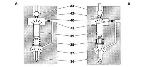
With injector closed;
B opening of one injector;
34 - control solenoid pintle;
36 - injector pintle;
37 - pressure chamber;
38 - injector spring;
39 - control piston;
40 - control chamber;
41 - feed nozzle;
42 - fuel return circuit nozzle.
- fuel is lost via nozzle (42);
- fuel entering through nozzle (41) does not compensate for the loss through nozzle (42);
- the balance between the pressure in chambers (40) and (37) is lost;
- the pressure in pressure chamber (37) lifts the injector pintle;
- the control piston rises;
- fuel is sent to the piston head.
- the solenoid spring locks the solenoid pintle in its seat to block nozzle (42);
- fuel loss toward the return circuit is cut off;
- the pressure increase in control chamber (40) brings about injector closure;
- the balance of pressures between chambers (40) and (37) is re-established;
- the injector is ready for a new cycle.
Electrical properties
The electrical supply to a solenoid is broken down into 2 stages.a) Return stage.The return stage brings about rapid lifting of the solenoid pintle. This is limited to a few tenths of a millisecond (0.3 ms).The injector solenoid is supplied with:- a voltage of 80 Volts;
- a current of 20 A.
- a voltage of 50 Volts;
- a current of 12 A.
- It is not possible to supply an injector with 12 Volts (solenoid would be destroyed).
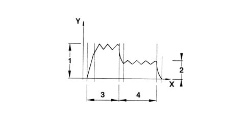
Injector control current.
Y - current (A);
X - duration (ms);
1 - return current;
2 - maintenance current;
3 - return stage;
4 - maintenance stage.
AIR SUPPLY CIRCUIT AND EXHAUST GAS RECIRCULATION CIRCUIT
Air supply circuit and exhaust gas recirculation circuit.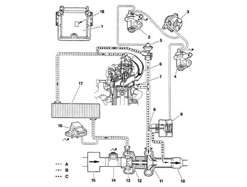
A - air;
B - exhaust gas + air;
C - exhaust gas;
1 - Engine management control unit;
2 - Exhaust gas recirculation regulation solenoid (EGR).
3 - Vacuum pump;
4 - Turbo pressure regulation solenoid;
5 - Exhaust gas recirculation valve (EGR);
6 - Intake manifold;
7 - Exhaust manifold;
8 - Wastegate;
9 - Wastegate pnematic control capsule (on turbocharger);
10 - Catalytic converter;
11 - Exhaust turbine;
12 - Turbo unit;
13 - Air compressor;
14 - Air flow meter + air temperature sensor;
15 - Air cleaner;
16 - Intake manifold pressure sensor;
17 - Air/air heat exchanger (intercooler);
18 - Atmospheric pressure sensor (built into the engine control unit).
TURBO UNIT
Function
The turbo unit turbocharges the engine.Description
The turbocharger consists essentially of two impellers (1) fitted to the same shaft (2). It turns on floating bearings that are lubricated by a branch (3) of the engine lubrication circuit.The exhaust-gas operated turbine turns the compressor to compress the intake air.The turbocharger is fitted with wastegate (4) controlled by pneumatic actuator (5) that cuts off part of the exhaust gas flow to the turbine on the basis of engine torque requirements.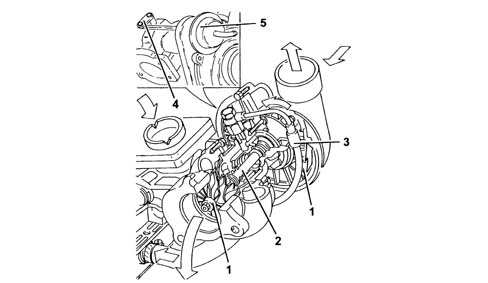
1 - Impellers;
2 - Shaft;
3 - Lubrication;
4 - Wastegate;
5 - Actuator.
AIR/AIR HEAT EXCHANGER (INTERCOOLER)
Function
The air/air heat exchanger cools air taken into the cylinders to increase air density inside.This increase in air density allows an increase in engine performance.VACUUM PUMP
Function
The vacuum pump provides the vacuum required to control the following components:- exhaust gas recirculation valve (E.G.R.);
- exhaust gas recirculation valve pneumatic control capsule;
- brake servo.
Description
The vane-type vacuum pump is driven directly by the camshaft.A safety valve built into the pump insulates the brake servo circuit with engine off. The safety valve makes it possible to maintain enough reserve vacuum in the brake servo for several braking manoeuvres.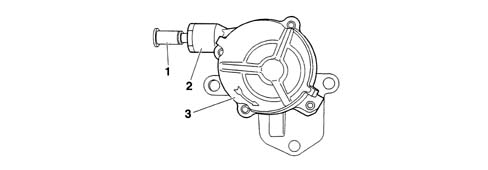
1 - outlet connection;
2 - safety valve;
3 - vacuum pump.
TURBO PRESSURE CONTROL SOLENOID
Function
The regulation solenoid controls the turbo pressure regulation valve with the aim of:- modulating turbo pressure;
- limiting turbo pressure.
Description
The solenoid is connected to the following elements:- atmospheric pressure;
- vacuum supplied by the vacuum pump.
Electrical properties
The solenoid control is variable DC (Duty Cycle) voltage type:- maximum supply voltage (maximum DC) = maximum vacuum;
- no supply (minimum DC) - no vacuum (atmospheric pressure).
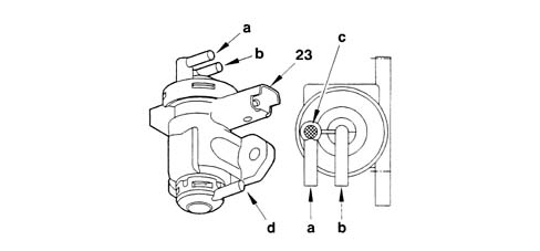
a - user outlet;
b - vacuum pump vacuum intake;
c - white marking;
d - atmospheric pressure input.
Wastegate control circuit operation
Turbo pressure is governed by solenoid (4) controlled by engine control unit (1).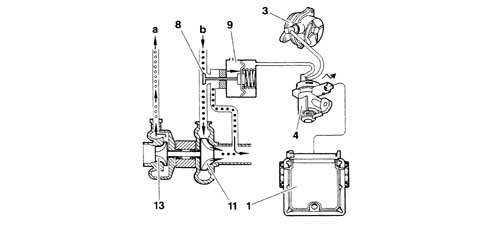
a - to intake distributor;
b - gas from exhaust manifold;
1 - engine management control unit;
3 - vacuum pump;
4 - turbo pressure regulation solenoid;
8 - wastegate;
9 - Wastegate pnematic control capsule;
11 - exhaust turbine;
13 - air compressor;
EXHAUST GAS RECIRCULATION VALVE (EGR)
Function
The exhaust gas recirculation valve controls the amount of exhaust gas recycled.The exhaust gas recirculation device (EGR) brings about a reduction in the amount of nitrogen oxice (NOx) released at the exhaust by taking a proportion of the exhaust gases back into the cylinders.Description
The recirculation valve is located on the exhaust manifold.Operating stages:- when the pneumatic control capsule is not controlled pneumatically, the recirculation valve closes;
- when the pneumatic control capsule is controlled pneumatically, the recirculation valve opens;
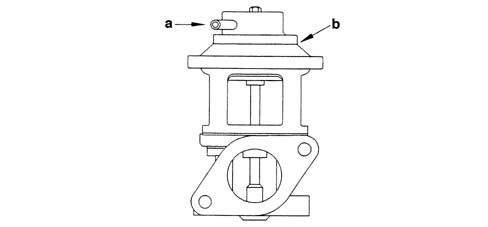
a - vacuum intake (gas recirculation regulation soleonid);
b - exhaust gas recirculation valve pneumatic control capsule.
EXHAUST GAS RECIRCULATION SOLENOID
Function
The solenoid brings the vacuum pump into communication with the exhaust gas recirculation valve capsule.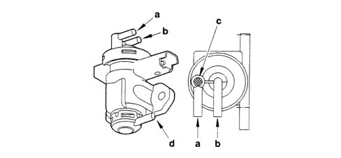
a - outlet;
b - vacuum pump vacuum intake;
c - white marking;
d - atmospheric pressure input.
AIR FLOW METER
Function
The flow meter measures the air mass taken in by the engine. According to the information received, the engine control unit:- determines the exhaust gas recirculation rate;
- limits black fume generation during transitory stages (acceleration, deceleration) by correcting fuel deliver.
Description
The flow meter is located between the air cleaner and turbocharger. It consists of the following components:- metal plate (hot film);
- air temperature sensor;
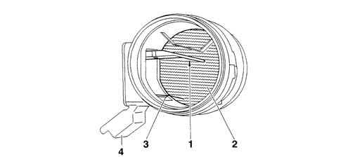
1 - metal plate (hot film);
2 - protective grid;
3 - air temperature sensor;
4 - electrical connector.
OIL VAPOUR RECIRCULATION SYSTEM (BLOW-BY)
Oil vapour emissions are controlled by an cylinder head intake pipe (1) downstream of the air cleaner.A proportion of the vapours condenses and returns to the sump through pipe (2), connected in turn to filler fitting (3).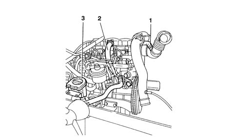
1 - cylinder head vapour intake pipe;
2 - oil return pipe to sump;
3 - oil filler fitting.
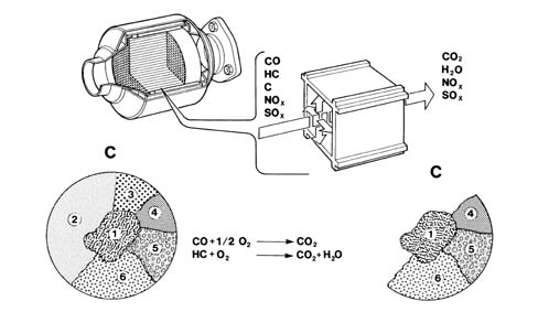
OXIDISING CATALYTIC CONVERTER
The catalytic converter is a simple, effective post-treatment device that oxidises most of the CO, HC and particulate to create carbon dioxide and steam.Initially, exhaust gases pass through the cells to heat the catalytic converter to trigger pollutant conversion: because the conversion is strongly exothermic (combustion), the catalytic converter is then able to maintain the high internal temperature required to ensure efficient conversion.Conversion efficiency is estimated to be as follows: CO 50%; HC 50%; particulate: 30The catalytic converter service temperature range (within which conversion efficiency is maximum) is between 200°C and 350°C.If the catalytic converter is the correct size, temperature can be controlled and sulphur compound oxidation can be limited.