Descriptions
CONSTRUCTION SPECIFICATIONS
Engines: 2.0 16V
FUEL TANK
The 80 litre capacity fuel tank is made out of plastic.It is equipped with a flexible filler fitting and includes a seat for installation of the fuel pump assembly. It is also equipped with seats for housing fuel evaporation control system components.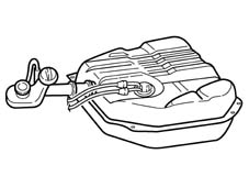
ELECTRIC FUEL PUMP
The pump is housed inside the tank in a special cradle and contains a mesh filter on the intake side. The pump used in this system is volumetric type. It houses a cut-off valve and a pressure relief valve set to a value of 6.5 ± 0.5 bar that by-passes the output to the input when high pressures occur to prevent the electrical motor from overheating. Operating voltage ranges from 7 to 15 volts.The pump operates at temperatures between -30 °C and +70 °C and its rated output is 140 l/h at a pressure of 2.5 bar and a supply voltage of 12V.It is supplied via a relay controlled directly by the ECU: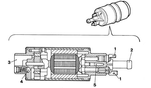
INERTIA SWITCH
If the vehicle suffers an impact, the inertia switch, fitted in the engine compartment on the bulkhead near the battery, interrupts the connection to earth (a) of the fuel pump (b) and closes the solenoid valves for the canisters (c) and the pressure reduction unit and, as a result, the supply to both systems is interrupted.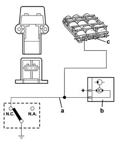
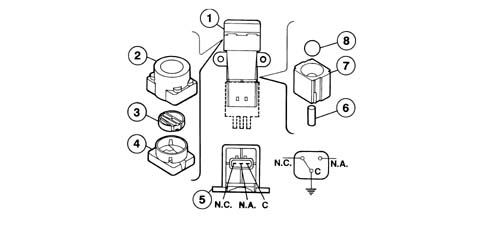
Intertia switch components
The following figure shows the inertia switch components,