The Marelli 48P.2 system fitted to the 1998 8v engine belongs to the category of integrated systems with digital electronic control via an ignition microprocessor with static advance and distribution and phased indirect intermittent multipoint injection.In this operating mode there are no functional variations in relation to the basic system.The Magneti Marelli 48P.2 basic electronic unit performs in the same way and the system management strategies are the same as for the basic version.The specific elements for the LPG system or the methane system do not, in any way, interfere with the basic system.The Marelli 48P.2 system is able to record a set of parameters via specific sensors or voltage data:engine rpm;the correct cylinder combustion TDC sequence (injection timing);absolute pressure in the intake manifold;intake air temperature;coolant temperature;throttle position and closure/opening speed;presence of oxygen in the exhaust gases;vehicle speed;exhaust gas recirculation solenoid position;the possible presence of detonation;the possible engagement of the air conditioning;the possible power assisted steering end of travel;battery voltagecommunicate with the Metatron METAFUEL 5D0 control unit via a high-speed CAN line.The analogue signals are converted into digital signals by analogue/digital (A/D) converters so that they can be used by the control unit.The control unit memory contains a management program (software) that includes a set of strategies, each of which manages a specific system control function.Each strategy uses the information (input) described above to process a set of parameters based on data maps stored in specific areas of the control unit. The strategy then controls the system actuators (output), i.e.the devices that allow the vehicle to operate, namely:control relays;injectors;ignition coils;actuation solenoids;interface with other control units on the vehicle (LPG or methane, automatic transmission, ABS, speed regulator etc.);interface with the in-car service control unit (in-car computer, climate control system, coded immobiliser).
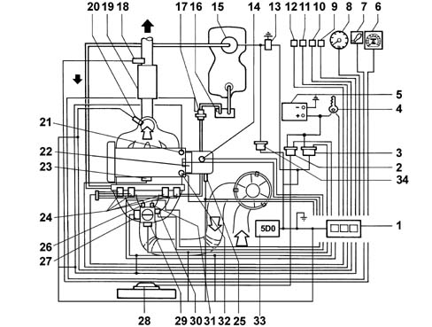
INJECTION - IGNITION SYSTEM OPERATING DIAGRAM
The following diagram shows the injection - ignition system operating diagram1 - Engine management control unit2 - Engine cooling fan relay3 - Engine control system relay4 - Ignition switch5 - Battery6 - Speedometer7 - System failure bulb8 - Rev counter9 - Automatic transmission control unit connection (if present)10 - Speed regulator connection (if present)11 - In-car service control unit connection (in-car computer, climate control system, coded immobiliser)12 - Diagnostic tester connection13 - Inertia switch14 - Vehicle speed sensor15 - Cradle (includes electric pump, fuel gauge and pressure regulator)16 - Carbon filter17 - Carbon filter scrubbing solenoid18 - Lambda sensor downstream of the catalytic converter19 - Catalytic converter20 - Lambda sensor upstream of the catalytic converter21 - Engine timing sensor22 - Ignition coil23 - Knock sensor24 - Injectors25 - RPM and TDC sensor26 - Intake air temperature sensor27 - Throttle position sensor28 - Engine cooling fans29 - Intake manifold absolute pressure sensor30 - Engine idle adjustment actuator31 - Throttle body heater32 - Coolant temperature sensor33 - LPG or methane engine management control unit34 - Petrol pump cut out relay
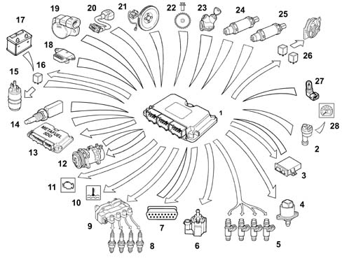
DIAGRAM SHOWING INFORMATION ENTERING/LEAVING THE CONTROL UNIT
Communcation between the petrol engine management control unit and the LPG or methane engine management control unit takes place via the CAN line.1, Electronic control unit2, Speedometer sensor3, CODE control unit4, Engine idle speed actuator5, Petrol injectors6, Fuel vapour solenoid valve7, Diagnostic socket8, Spark plugs9, Ignition coils10, Engine coolant overheating warning light11, Injection failure warning light12, Climate control system13, LPG or methane engine management control unit14, Engine coolant temperature sensor15, Petrol pump16, Petrol pump cut out relay17, Battery18, Air pressure sensor19, Throttle valve position sensor20, Detonation sensor21, Rpm and TDC sensor22, Injection timing sensor23, Ignition switch24, Lambda sensor (pre-catalyzer)25, Lambda sensor (post-catalyzer)26, Radiator fan high and low speed relays27, Intake air temperature sensor28, Speedometer/milometer
MAIN MANAGEMENT STRATEGIES
Operating principle
All engine service points can be identified by means of two parameters:rpm;engine load.Once these parameters have been obtained by processing, it is possible to calculate and then implement the injection (amount of fuel delivered and timing with combustion TDC), ignition (correct ignition advance) and any other functions for each engine service point.In the Marelli 48P.2 system, rpm is measured directly by a sensor while engine load is determined indirectly on the basis of absolute pressure and air temperature, both measured in the intake manifold.Specific ignition maps are drawn up during engine and vehicle testing. These store injection time/stage and ignition advance values and all other parameters required for correct engine operation.These values are determined by mathematical extrapolation of parameters for any service point, even points that are not specifically mapped.Calculated injection time values are also corrected on the basis of the signal from the lambda sensor, which determines continuous fluctuation of the mixture content about a stoichiometric level on the basis of specific operating strategies.The system is therefore defined as "speed-density-lambda" type because injection time is mainly determined by these three parameters.All specific operating situations that require specific adaptation of injection time/stage, ignition advance and other calculated parameters are managed by the engine management unit on the basis of signals from various system sensors.
Signal framework mangement
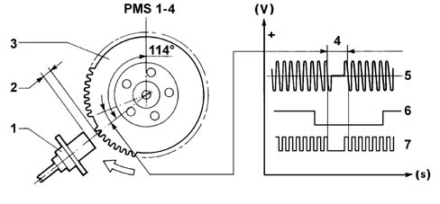
The term "signal framework" denotes the set of signals from a sensor on the crankshaft and a sensor on the camshaft. Because these are related by a specific reciprocal position, they provide the control unit with a synchronised signal sequence that that control unit is able to recognise.During starting the control unit recognizes the injection and ignition timing which are vital for the subsequent operation of all strategies.This recognition is implemented on the basis of the interpretation of the series of signals from the phonic wheel sensor located on the crankshaft and the engine timing sensor on the camshaft.The rpm sensor gives a reference for the angular position of the crankshaft (TDC identification). It is secured to the gearbox bell housing and faces the phonic wheel.1 - RPM and TDC sensor2 - Gap3 - Phonic wheel 60-2 teeth4 - Signal corresponding to two missing teeth5 - Phonic wheel signal (engine speed sensor)6 - Engine timing sensor signal7 - Converted phonic wheel signalThis consists of a sealed tubular case containing a permanent magnet and an electric winding or copper coil. It is connected to the electronic control unit via terminals B1 and B2 of connector H32V/C. The wires are twisted 40 coils/metre and covered by a shielded interference-proof sheath connected to earth. A heat-resistant PVC sheath covers leads and shielding.Phonic wheel (3) consists of 58 teeth plus a gap equivalent to the space occupied by the two missing teeth. The reference defined by the space left by the missing teeth constitutes the basis for recording the synchronism point (TDC).The synchronism poinnt is recognised at the end of the first tooth following the gap left by the two missing teeth: when this passes beneath the sensor, the crankshaft is located with piston pair 1-4 at 114° before TDC.Operation is as follows: The sensor permanent magnetic field affects the winding and also the phonic wheel teeth. In practice, when the tooth is in front of the sensor, the magnetic flow is maximum. When the gap passes, the flow is minimum. During phonic wheel rotation, whenever a tooth tends to approach the sensor, the signal rises toward the positive voltage value (+). It becomes zero during the tooth-sensor alignment stage and passes through a negative voltage value (-) as the tooth moves away.The graph and the waveform (which corresponds to the mechanical position of the phonic wheel) is an e.m.f. set up in the sensor winding and may range from a few volts at low rpm to several tens of volts at a high rpm. Because the resulting voltage depends on the distance between sensor core and tooth tip, it is extremely important that this height, known as the GAP is between 0.5 - 1.5 mm.The train of analogue signals generated by the sensor is sent to an appropriate converter circuit (A/D analogue digital) in the electronic control unit (ECU) and used for:calculating the engine rpm;calculating the optimal ignition advance.
Management of the injection
The injection management strategies are designed to provide the engine with the correct amount of fuel at the desired time depending on the engine operating conditions.
Calculating basic injection time
Injection management essentially involves computing injection time, determining injection stage and subsequent implementation of the stage by controlling the injector.Base pulse constant is calculated by mathematical extrapolation from the speed-load map. the experimentally obtained mapped values also depend on injector specifications. The final injection time is determined by means of a calculation algorithm whereby the base pulse constant is corrected by a series of coefficients that take into account the different engine operating conditions.
Cold start-up and running
During cold starting the injection is managed simultaneously (full-group), in other words it is not phased: this situation persists until the engine started. After this, management becomes phased.During cranking by the starter motor, injection time is determined by a special map and depends on coolant temperature and barometric pressure.During cold operation, the base pulse constant is increased as appropriate by a factor inversely proportional to coolant temperature.
Full load
This strategy is enabled when the throttle exceeds a certain threshold: injection time is increased in this situation.
Acceleration and deceleration
The acceleration or deceleration situation represents a transitory state that may be positive (acceleration) or negative (deceleration).The transitory management strategy is very complex: in general, injection time is increased for positive transitories and reduced for negative states.The correction identify depends fundamentally on load and engine speed changes, throttle movement speed and engine temperature.
Cut off
The control unit enables cut off strategies when engine speed exceeds a certain threshold.The cut-off strategy is implemented when the control unit detects the throttle in idle position (throttle potentiometer signal).Engine fuel supply is re-enabled when the throttle is detected in an unclosed position or when speed drops below a threshold higher than the enablement threshold.
Rotation speed limiter
The strategy limits the maximum speed achievable by the engine by enabling cut-off.
Fuel pump drive
The fuel pump is controlled by the engine management unit via the relay.The pump stops:if engine speed drops below a certain minimum threshold;after a certain time (about 5 seconds) with the key ON without start-up taking place (timed enablement);if the inertia switch is operated.
Injector control
Altitude correction
- The control unit detects atmospheric pressure and uses it to make appropriate corrections under the following conditions:- with ignition switch in MAR position,- with engine under high load and with low rpm.The control unit detects atmospheric pressure and uses it to make appropriate corrections under the following conditions:with ignition switch in MAR position,with engine under high load and with low rpm.
Management of the ignition
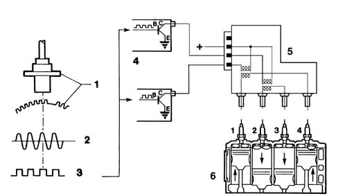
Ignition management essentially consists of determining the required ignition advance on the basis of engine service conditions and then implementing the advance by controlling a power transistor located inside the control unit. The baseline advance value, calculated on the basis of engine load and speed, is then corrected on the basis of the various engine service conditions. The primary winding of each coil is supplied by battery voltage via a relay and is connected to the power transistor manifold built into the engine control unit. The broadcasting unit is earthed while the base receives control voltage from the control unit.According to engine rotating speed and ignition advance to be implemented, the engine control unit establishes the moment at which conduction begins in the primary winding in order to achieve the required current intensity (saturation) in the primary winding immediately before interrupting the current. The angle of this moment naturally changes in relation to the combustion TDC of each cylinder: its advance is directly proportional to engine rpm because the time required to saturate the current in the coil primary winding is more or less constant: this is determined using appropriate coefficients stored at the mapping stage (dwell management).1 - RPM and TDC sensor with phonic wheel2- Control unit input signal3 - Signal converted in control unit (square wave)4 - Internal power module5 - Coil6 - Spark plugsThe conduction start moment is also corrected on the basis of battery voltage.The engine management unit therefore determines the moment at which current is cut off in the primary winding and converts the degrees of advance into the time required by the engine to move through this angle: this time is the advance in relation to combustion TDC with which the current at the base of the transistor is interrupted.At the time when the current interrupts the current at the base of the power transistor, the primary winding earth connection is interrupted and a high tension discharge is therefore triggerd in the secondary coil.
Start-up
During starting, the normal management of the advance cannot be carried out because the considerable fluctuations in the rotation speed do not allow the dwell and the advance to be correctly calculated.The control unit implements a fixed advance throughout the time the engine is cranked by the starter motor.
High temperatures
The base advance value is reduced when intake air temperature exceeds a certain threshold.
Cut off
The injection advance is reduced on entry into cut-off. from the moment the supply of fuel is resumed, the advance is gradually restored to the "basic" value.
Take-off
The strategy reduces advance during vehicle take-off from a standing start.
Engine idling
When the engine is idling, the management of the advance is implemented independently of the "basic" advance.The idling advance value is corrected by a factor inversely proportional to the speed change in relation to a preset speed, in turn dependent upon coolant temperature.In particular, advance is increased if speed drops and is reduced if speed increases to ensure speed stability.
Knock control
This strategy detects the presence of knock effects by processing a signal from the appropriate sensor. The strategy continuously compares a signal from the sensor with a threshold which is in turn continually updated to take into account background noise and engine ageing.If the system detects the presence of knock, the strategy reduces the ignition advance until the effect disappears. The advance is then gradually restored to the baseline value or until the effect begins to arise again.As advance is reduced, injection time is increased to prevent a dangerous increase in exhaust gas temperature.
Engine idle speed control management
The general aim of the strategy is to maintain engine speed around a stored value: the position assumed by the actuator is dependent on engine conditions and rpm and vehicle speed.
Starting.
When the ignition key is inserted, the actuator takes up a position dependent on engine temperature and battery voltage (open-loop position).
Engine running and accelerator pedal released.
Engine speed varies according to engine temperature and is maintained constantly close to this value by altering plunger position to make up for any speed fluctuations.This takes place particularly when external loads are activated (headlamps, heated rear window etc.).When the air condition is activated and/or the power steering reaches the end of its travel, the strategy manages the actuator ahead of load activation due to the presence of load signals.
Normal motion.
The actuator is in open-loop -position under these conditions.
Over-run.
Under conditions of over-run, the control unit controls plunger position through a specific output curve (dash-pot curve), i.e. it delays the plunger's return to its seat to reduce the engine brake effect.If the vehicle is in over-run status, information on speed in relation to engine speed allows the dash-pot effect to be managed and adjusted to the gear engaged.
EMISSION CONTROL DEVICE MANAGEMENT
Active charcoal filter scrubbing solenoid
The strategy controls carbon filter scrubbing solenoid position as follows:during start-up, the solenoid remains closed to prevent fuel vapours enriching the mixture;after a cold start, the solenoid remains closed throughout the engine heating stage;with the engine warm, the control unit controls the solenoid through its duty cycle to control the amount of fuel vapour sent to the intake (carbon filter scrubbing) on the basis of engine speed and load. In particular, the system alternates periods of scrubbing with periods of non-scrubbing: during the latter periods, the self-adaptive strategy is implemented while it is disabled during scrubbing;the solenoid remains closed during cut-off.
Lambda sensor heater
The control unit controls the heating power supply of both lambda sensors to bring the sensor up to steady-state conditions quickly and maintain temperature at optimum levels.
Self-adaptation
The system includes a set of self-adaptive strategies for the following functions:mixture concentration control strategy (*)engine idle speed control strategy (*)knock control strategy (*)throttle closed position learning strategy (*)transmission ratio learning strategy.Self-adaptive strategies are designed to adapt the system to engine specifications and changes (ageing).The values are saved in the control unit permanent EEPROM whenever the ignition switch is turned OFF (generally when the engine is switched off).These values are also preserved under the following circumstances:Memory deletionControl unit connector disconnectionBattery disconnectionControl unit remote loading.Then, after each operation on the following components:Lambda sensor and injectors;Idle adjustment step motor;Knock sensor;Throttle potentiometer;the defect deletion procedure must be carried out to recover the self-adaptive values stored in the control unit memory.After carrying out the defect deletion process, the extreme positions of the throttle potentiometer must be detected as follows:Engine running;Accelerator pedal in rest position;Press the accelerator pedal to the floor for a moment;Release the accelerator pedal.
Radiator fan management
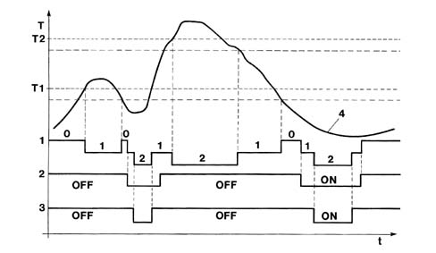
The engine control unit controls radiator fan activation on the basis of cooloant temperature and presence or absence of a climate control system.Two fan operating speeds are provided for versions with climate control system. These are managed in accordance with two different strategies:on the basis of coolant temperature: low speed: is activated when coolant temperature reaches threshold T1; high speed: is activated when coolant temperature reaches a threshold T2; deactivation takes place with a temperature hysteresis of about 3°C.on the basis of climate control system pressure switch condition: low speed: is activated when the pressure switch switches to level II; the high speed: is activated when the pressure switch switches to level III.ON pressure switch activeOFF pressure switch deactivated1 - Fan status 0=off/1=low speed/2=high speed2 - pressure switch level II3 - pressure switch level III4 - Engine coolant temperature curve
DIAGNOSTICS
The system is fitted with a self-diagnostic function that checks for faults in the system.
Eobd
The control unit is equipped with a specific diagnostic system for the emission control system (EOBD, European On Board Diagnostic) This monitors the operation of all components that could directly or indirectly affect the correct operation of the emission control system.Apart from component diagnostics, the system mainly performs the following functions:checking efficiency of the catalytic converter by means of a downstream lambda sensor;control of irregular combustion (that could irreparably damage the catalytic converter) by analysing signals from the rpm and engine timing sensors to differentiate between situations due to other causes (road conditions etc.).Detectable faults are classified from into two categories from the viewpoint of on-board diagnostics (see the following table):slight defect that does not involve particular consequences;severe defect that involves a danger of exceeding the emission limits.The fault also undergoes a validation procedure to exclude the possibility of sporadic situations or situations due to specific conditions.Fault detection, if validated, leads to the fault being permanently saved and also exclusion of the sensor from the system until it is repaired.The fault is automatically deleted from the memory after 40 operating cycles without detection.An operating cycle consists of start-up, achievement of engine steady state temperature and subsequent key off.
Warning light bulb
Fault detection normally involves activation of a warning light on the dashboard in accordance with the following strategy:ignition switch OFF: warning light off;ignition switch ON, engine off: warning light on:ignition switch ON, engine running, no permanent severe defect;if the contact has been on for more than three seconds before engine start-up, the warning light goes off immediately;if the contact has been on for less than three seconds before engine start-up, the warning light goes off after three seconds;ignition switch ON, engine running, at least one permanent severe defect present: warning light onThe warning light bulb goes off if the defect changes from permanent to temporary. This change becomes operational after the successful completion of a diagnostic sequence.Defining a diagnostic sequence:engine start-up;when control unit tested for faulty function, the defect was no longer detected;engine turn off.The warning light bulb fails to come on in the following cases:speed irregularities caused by poor road conditions;start-up failure or stalling caused by fuel level dropping below minimum in fuel tank.Under these conditions, the engine management control unit inhibits the diagnostic function.
Active diagnostics
The system can be tested using the diagnostic tester in three stages:display of a set of operating parameters (with engine off or running). A set of operating menus subdivided according to the various menus can be displayed in real time.display of errors present and error deletion. Errors are displayed up to a maximum of 10, of which 3 reserved for the EOBD. In some cases it is possible to identify fault specifictions i.e.: open circuit, short circuit to earth, short circuit to battery positive, consistency;activation of some components/functions (active diagnosis): it is possible to test the operation of the following components/functions that are governed independently of the engine control unit: engine idle adjustment actuator, injectors, fuel pump relay, carbon filter scrubbing solenoid, heating of lambda sensor upstrem of catalytic converter, heating of lambda sensor downstream of catalytic converter, radiator fan, coils, rev counter signal, diagnostic warning light, excessive coolant temperature warning light.Conditions for carrying out active diagnosis are as follows:ignition switch in ON position;engine off;vehicle at standstill
Recovery strategy
If the sensors are found to be faulty, the control unit replaces the missing data, if possible, by reconstructing it using software (recovery) so that the engine will continue to operate.
List of functions that can be tested
Definition
Minor fault
Serious fault
Recovery functions
engine management control unit
X
---
---
battery voltage
X
---
X
coolant temperature sensor
X
---
X
air temperature sensor;
X
---
X
absolute pressure sensor
X
---
X
throttle position sensor
X
---
X
injection timing sensor
X
---
---
engine speed sensor
X
---
X
knock sensor
X
---
X
upstream lambda sensor
X
---
X
downstream lambda sensor
X
---
---
vehicle speed sensor
X
---
X
radiator fans
X
---
---
sensor power supply
X
---
X
ignition coil control (both)
X
---
X
injector control
X
---
---
engine idle speed adjustment actuator control
X
---
---
carbon filter scrubbing solenoid control
X
---
---
upstream lambda sensor heating control
X
---
---
downstream lambda sensor heating control
X
---
---
Mixture concentration self-adaption
X
---
---
coolant temperature warning light bulb control (BSI)
X
---
---
coolant temperature temperature gauge control (BSI)
X
---
---
radiator cooling fan 1 control relay control
X
---
---
radiator cooling fan 2 control relay control
X
---
---
engine speed information (BSI)
X
---
---
system failure bulb control
X
---
---
system failure line control
X
---
---
climate control system compressor information
X
--
---
automatic transmission communication (CAN line) (if present)
X
---
---
mixture concentration information
X
---
---
coded immobiliser communication
X
---
---
coded immobiliser code store
X
---
---
catalytic converter ageing information
X
---
---
exhaust gas recirculation system information
X
---
evaporation control system information
X
---
fuel injection system information
X
---
mixture concentration information
X
---
misfiring
---
X
---
automatic transmission communication (CAN line) (if present)
X
X
---
ELECTRIC - ELECTRONIC CIRCUIT
Engine management control unit
The control unit uses a FLASH EPROM. This new technology allows settings to be changed (e.g. to improve driving comfort) without having to remove the control unit or replace the EPROM.The operation involves remote loading of a new program into the control unit memory by means of the tester via the tester input after checking that system elements are working normally (no faults).
Functions managed by the control unit
Calculation of injection time and baseline ignition advance (intake air temperature sensor and absolute pressure sensor, engine speed sensor);calculation of injection time corrections on the basis of specific conditions (lambda sensor signal, coolant temperature sensor, engine speed sensor, throttle position sensor, engine speed sensor, battery voltage etc.);calculation of injection advance corrections on the basis of specific conditions (coolant temperature sensor, vehicle speed sensor, throttle position sensor, engine speed sensor, battery voltage, knock etc.);injector control (engine timing sensor, power transistor, injectors);coil control (power transistor, coils);engine idle speed ajustment (idle speed adjustment actuator);sensor power supply;fuel supply (fuel pump);throttle body heating (throttle body heater);lambda sensor heating (lambda sensor heater);carbon filter scrubbing (carbon filter scrubbing solenoid);information on engine speed (rev counter) and vehicle speed (speedometer);self-diagnosis;system failure warning light bulb (instrument panel);connection with service tester and EOBD tester;connection with automatic transmission control unit connection (if present);connection to on-board service control unit (climate control system, on board computer, coded antitheft control unit etc.).communication with the Metatron METAFUEL 5D0 control unit via a high-speed CAN line that is used to exchange data, commands and other information.
Control unit pin out
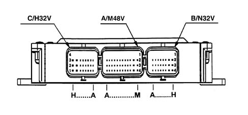
The following diagram shows engine management control unit connectors.
Injection-ignition system wiring diagram
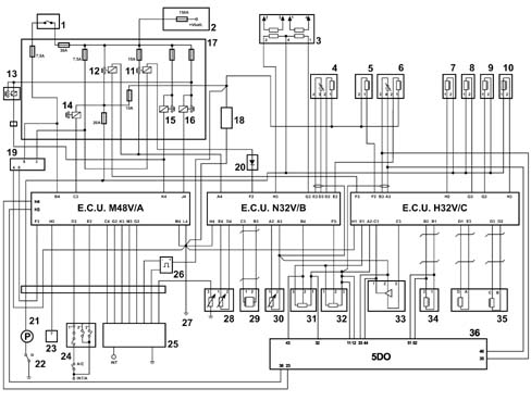
The following diagram shows the injection - ignition system wiring diagram.1 - Ignition switch2 - Battery control unit3 - Ignition coil4 - Heated lambda sensor (downstream of the catalytic converter)5 - Canister solenoid6 - Heated lambda sensor (upstream of the catalytic converter)7 - Cylinder no. 1 injector.8 - Cylinder no. 2 injector.9 - Cylinder no. 3 injector.10 - Cylinder no. 4 injector.11 - ECU relay12 - Power relay13 - High engine cooling speed relay (only with A/C)14 - Compressor relay15 - High engine cooling speed relay16 - Low engine cooling speed relay17 - Engine bay control unit18 - Oil vapour heater19 - Immobilizer control unit20 - Diode on wiring 21 - Electric fuel pump22 - Inertia switch23 - EOBD input24 - 4 stage pressure switch25 - Instrument panel26 - Speedometer pulse generator27 - Chassis earth28 - Engine coolant temperature sensor29 - Knock sensor30 - Air temperature sensor31 - Throttle valve potentiometer32 - Timing sensor33 - Air pressure sensor34 - Engine rpm sensor35 - Idle speed control actuator36 - LPG or methane engine management control unit
Fuel supply manifold
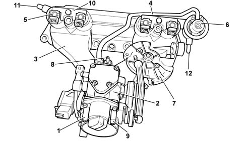
The fuel supply manifold that distributes fuel to the injectors is made in one piece and integral with the air intake manifold. The intake manifold is made out of synthetic material and contains air ports, fuel ducts and seats for injectors and the pressure regulator. This type of construction is made possible due to the use of side feed injectors and a pressure regulator - also integral.1 - Secondary blow-by intake2 - Throttle body3 - Intake manifold4 - Fuel pressure regulator signal intake5 - Injector6 - Fuel pressure regulator7 - Accelerator control screw8 - Absolute pressure sensor signal pipe9 - Carbon filter scrubbing intake10 - Injector pair retaining plate11 - Fuel inlet12 - Fuel return
Petrol injectors
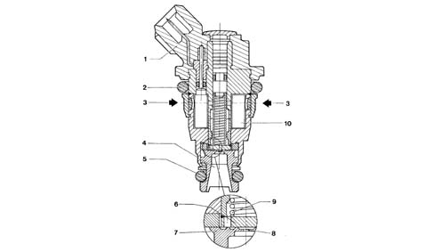
The injectors are installed on the intake manifold immediately upstream of the intake valve: they are positioned to ensure that the fuel jet is directed onto the intake valve.The injectors are side feed type, i.e. fuel (3) is fed in at the side of the injector body. This feature allows the fuel manfold to be made integral with the air intake manifold and thus reduce the risk of vapour lock inside the injector. Two o-rings (2) and (5) provide an effective fuel seal.The injectors are also pintle-less, i.e. they lack a pintle. This feature offers the benefit of significantly reducing injector cost because the pintle and tapered seat are no longer required. These particular parts require very tight working tolerances and are therefore very costly. The reduction in jet nebulisation that is a consequence of eliminating these parts has not been found to critically effect effective engine operation under all conditions.The injectors consist of a plunger (6) controlled by electromagnet (10) and held in place by spring (9). Electrical connection (1) is built into the top part of the body.In rest position, plunger (6) is pressed by spring (9) against seat (7) in order to close nozzle (8) and ensure a seal. As soon as winding (10) is excited, plunger (6) is attracted to it and compresses spring (9). This opens nozzle (8) so that fuel can flow out from diffuser cone (4).Assuming physical fuel properties (viscosity and density) and the pressure gap (pressure regulator) to be constant, injected fuel quantity depends only on injector opening time.From an electrical viewpoint, the injectors are resistance type with a coil resistance of 14.5 ohms.The LPG injectors are described in the relevant chapterCharacteristic of working principle1057ALIMENTAZ. GPLThe methane injectors are described in the relevant chapterCharacteristic of working principle1058ALIMENTAZIONE CNG
Fuel pressure regulator
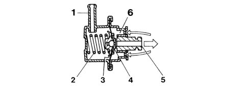
The pressure regulator is required to maintain a constant pressure difference at the petrol injectors.It is a differential membrane-type device set to 2.5 ± 0.05 bar during assemblyPressurised fuel from the pump brings about a thrust on membrane (3) of cut-off valve (4) countered by calibrated spring (2).When this set pressure is overcome, outlet valve (4) moves to allow excess fuel to return to the tank.The pressure regulator is affected by the vacuum in the intake manifold (where the injectors are housed). The vacuum change experienced at the tip of the injector therefore also affects the regulator membrane. This ensures the pressure difference at the injector terminals is maintained constant under all engine service conditions.The fuel output therefore depends exclusively on injector opening time.1 - Pressure signal intake2 - Counter spring3 - Membrane4 - Cut-off valve5 - Fuel outlet (to return pipe)6 - Fuel intake (from fuel manifold)
Engine speed sensor
The sensor is fastened to the engine block on the flywheel side.
Operating principle
The sensor takes the form of a tubular case (1) containing a permanent magnet (3) and an electrical winding (2).Due to the passage of the phonic wheel teeth, the magnetic flux set up by magnet (3) undergoes fluctuations due to changes in the gap.These fluctuations set up an electromotive force in winding (2) and a voltage is set up at the terminals that is alternatively positive (tooth facing sensor) and negative (gap facing sensor). Rpm sensor peak output voltage depends, all else being equal, on the distance between the sensor and the phonic wheel teeth (gap).Sensor resistance may be measured by disconnecting the connector and connecting an ohmmeter at the sensor terminals:Resistance: 350 %mnplus; 15% ohm at 20° C
Throttle position sensor
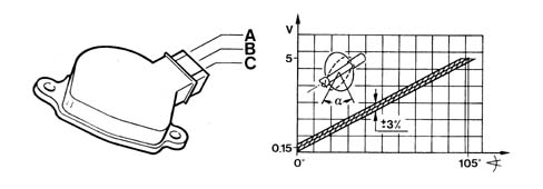
The throtte position sensor consists of a potentiometer with its mobile part controlled by the throttle valve spindle.During operation, the electronic control unit supplies the potentiometer with a voltage of 5 Volts. The parameter measured is throttle position from idle to full opening for injection control management.According to output voltage, the control unit detects the throttle opening condition and corrects the mixture concentration as appropriate.With the throttle closed, an electric voltage signal is sent to the control unit, which detects Idle and Cut off conditions (discerning between them on the basis of engine rpm).The potentiometer is single-ramp type. Its main features are:Effective electrical angle: 90° %mnplus; 2°Mechanical angle: 105° %mnplus; 3°Total mechanical travel: 110° %mnplus; 8°Temperature operating range: - 40°C - +125°CTrack resistance: 4150 ± 20% Q to be measured between pins A and CThe potentiometer is contained in a plastic case with two tabs. This includes two unslotted holes so that the potentiometer may be secured to the throttle body without the possibility of adjustment.A - Positive +5VB - SignalC - Negative
Absolute pressure sensor
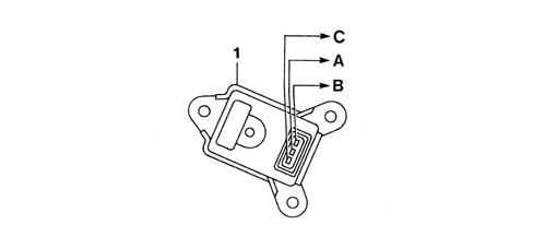
The sensitive element (Wheatstone bridge) is screen printed on a very fine, circular ceramic plate (membrane) fitted to the lower part of a ring-shaped mount made out of the same ceramic material.The upper part of the seal is closed by another plate that also acts as a support for the signal electronic amplifier.A circuit is fitted to the Wheatstone bridge signal output. This compensates for thermal drift in all fields of use after a series of laser settings with the laser working at different temperatures.The sensor is installed in a plastic container fitted with a connection for the vacuum signal input from the intake manifold.With the engine off, the sensitive membrane deflects according to atmospheric pressure. Exact reference information on altitude can therefore be obtained with key on.During operation, the engine generates a vacuum that produces a mechanical action on the sensor ceramic membrane, which deflects to alter the resistance value.Because the power supply from the control unit is maintained strictly constant (5V), the output voltage changes when the resistance value is altered.We therefore obtain: initial information on the amount of air taken in by the engine.The control unit uses this information, together with data from the air temperature sensor, to establish the density of intake air taking engine load into account.1 - Sensor casingA - NegativeB - Positive +5VC - Signal
Engine timing sensor
The engine timing sensor, together with the engine speed and TDC signal, allows the control unit to recognise cylinder sequence when implementing phased injection. This signal is generated by a Hall-effect sensor fitted near the exhaust camshaft.
Vehicle speed sensor
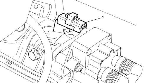
The sensor is located on the differential output near the left half-axle coupling. It transmits information relating to the speed of the vehicle to the control unit. The control unit uses this information to manage the engine idle speed adjustment actuator more effectively.The sensor works on the Hall effect principle.
Operating principle
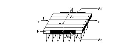
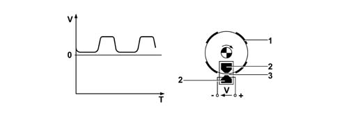
Current (I) flows through a semiconductor layer (Hall layer H). When the layer is crossed vertically by magnetic field B, a voltage (in the order of millivolts) is generated between contact surfaces (A1) and (A2) known as the Hall voltage (HV). If the intensity of the current remains constant, the VH only depends on the intensity of the magnetic field: the more intense the field, the higher the HV.H - Hall layerI - CurrentB - Vertical magnetic fieldA1 - Contact surfacesA2 - Contact surfacesThe magnetic field intensity simply needs to change periodically to generate a modulated electrical signal with a frequency proportional to the speed at which the magnetic field changes.To achieve this change, a metal rotor with slots is made to pass across the sensor. The signal is active when aligned with a gap but cut off when aligned with the deflector.1 - Deflector2 - Magnetic material3 - Gap
Air temperature sensor
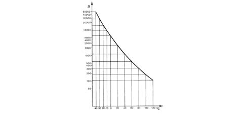
The sensor is installed on the throttle body.It consists of a plastic case with the actual resistance element fitted at one end. This takes the form of an NTC thermistor (Negative Temperature Coefficient - i.e. the sensor electrical resistance falls as temperature rises).1 - Connector2 - NTC sensor housingThe reference voltage is 5V. Because the control unit input circuit is designed as a voltage divider, this voltage is distributed between a resistance present in the control unit and the sensor NTC resistance. The control unit is therefore able to assess sensor resistance changes via changes in the voltage and thus obtain temperature information.The graph shows the sensor specification curve, which may be measured by disconnecting the connector and connecting an ohmmeter to the sensor terminals.
Engine coolant temperature sensor
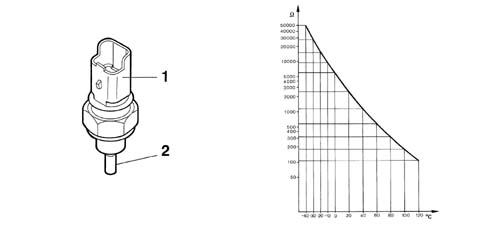
The sensor is installed on the thermostat body.It consists of a brass case that acts as the actual resistance element. It takes the form of an NTC thermistor (Negative Temperature Coefficient - i.e. the sensor electrical resistance falls as temperature rises).1 - Sensor connector2 - NTC pad housingThe reference voltage is 5V. Because the control unit input circuit is designed as a voltage divider, this voltage is distributed between a resistance present in the control unit and the sensor NTC resistance. The control unit is therefore able to assess sensor resistance changes via changes in the voltage and thus obtain temperature information.The graph shows the sensor specification curve, which may be measured by disconnecting the connector and connecting an ohmmeter to the sensor terminals.
Knock sensor
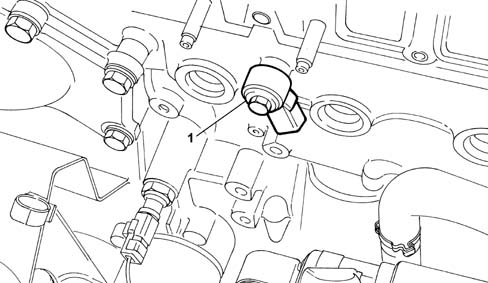
This piezoelectric sensor is fitted on the engine block in a symmetrical position in relation to cylinder pairs 1-2 and 3-4.This positioning is determined by the need to detect the onset of knock in a similar way for all cylinders.This sensor is used to measure knock, a vibration effect caused by irregular mixture combustion in the combustion chamber.If repeated, this effect may harm mechanical parts due to an anomalous temperature increase in the walls.
Ignition Coils
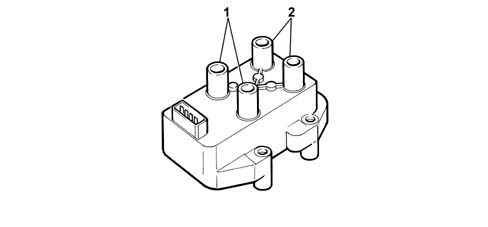
The coil used in this system is closed magnetic circuit type. It consists of a lamellar pack with a central core broken by a fine gap that holds both the windings.Both windings are positioned in a moulded plastic container and embedded in epoxy resin that gives them exceptional dielectric, mechanical and also thermal properties so that they are able to withstand high temperatures. The proximity of the primary winding to the magnetic core reduces magnetic flux loss to maximise coupling on the second winding and thus obtain the following results:Higher voltage reserve.Higher energy converted on secondary winding.Longer spark duration.Shorter secondary winding voltage increase times.Another benefit of resin-embedded coils over oil-bath coils is that they are safer. In the case of operating faults in the electronic control module (primary winding current limiter circuit defective), the coil takes up a very high current and geneates a lot of heat.1 - Cylinder 1 -4 coil2 - Cylinder 2 -3 coil
Throttle body
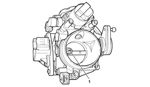
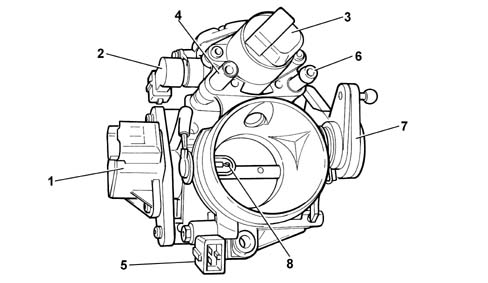
The throttle body is responsible for metering the amount of air supplied to the engine to meet the driver's requirements via the accelerator control. It is secured to the intake manifold by means of three bolts. The throttle is opened by a gradually-opening screw (7) to achieve small throttle opening angles at the beginning of the accelerator travel and large angles at the end of the travel for the same accelerator travel.With the accelerator pedal fully released (engine in over-run or idling), the amount of air taken in by the engine is supplied mainly by the by-pass controlled by the step motor (3). Under these conditions, the throttle opening screw abuts against an anti-bind screw that should never be tampered with.To prevent ice formation in the by-pass, the throttle body is equipped with a heater (2) supplied with electricity by a battery that heats the idle air by-pass area.The throttle body is also equipped with two intakes for secondary blow-by (4) and carbon filter scrubbing (6) respectively.The throttle body is also fitted with a throttle valve position sensor (1) and air temperature sensor (8) with connector (5).
Throttle body heater
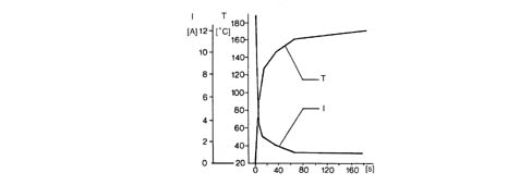
The throttle body heater heats the area adjacent to the idle air by-pass to prevent ice formation under certain conditions. This is achieved by binding a resistance pad (PTC) to a special recessed seat in the throttle body.Pad material is positive temperature coefficient type (PTC).Its resistance increases rapidly with increasing temperature. in this way, after around a minute, the current absorption is reduced to about 1 Ampere.T = TemperatureI = current intensityThe heated is supplied directly by the battery via the relay on the engine management unit drive.
Engine idle speed actuator
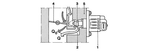
The engine idle actuator secured to the throttle body consists of:an electric step motor with two windings in the stator and a rotor that includes a certain number of permanent magnetic pole pairs;a worm screw reduction unit that converts rotatory motion into linear motion.1 - Bearing2 - Worm screw3 - Coils4 - Magnet5 - Screw6 - Grooves to prevent rotation7 - PlungerIn order to idle, i.e. with throttle (4) fully closed, the engine needs a certain amount of air (Qm) and fuel to overcome internal resistance and maintain its rpm.The amount of air (Qo) coming in from the filter, which leaks through the closed throttle valve (4) during idling, must be increased by an extra amount of air (Q) during engine warm-up or upon activation of electrical appliances or external loads (where present - air conditioner, automatic transmission etc.) to ensure idle speed remains constant.To achieve this result, the system uses a step motor (1) secured to throttle body (5) and controlled by a pilot circuit (6) located in the injection-ignition ECU. During operation, the step motor moves a rod with plunger (3) to alter the cross-section of by-pass duct (2) and thus the amount of air (Qo+Q) taken in by the engine. Pulses sent by the electronic control unit to the step motor are converted from rotatory motion to linear movements (about 0.04 mm/step) via a worm screw mechanism by operating a plunger whose movements alter the by-pass duct section.
1 - RPM and TDC sensor with phonic wheel2- Control unit input signal3 - Signal converted in control unit (square wave)4 - Internal power module5 - Coil6 - Spark plugs1 - RPM and TDC sensor with phonic wheel2- Control unit input signal3 - Signal converted in control unit (square wave)4 - Internal power module5 - Coil6 - Spark plugs1 - RPM and TDC sensor with phonic wheel2- Control unit input signal3 - Signal converted in control unit (square wave)4 - Internal power module5 - Coil6 - Spark plugs
Starting.
When the ignition key is inserted, the actuator takes up a position dependent on engine temperature and battery voltage (open-loop position).
Engine running and accelerator pedal released.
Engine speed varies according to engine temperature and is maintained constantly close to this value by altering plunger position to make up for any speed fluctuations.This takes place particularly when external loads are activated (headlamps, heated rear window etc.).When the air condition is activated and/or the power steering reaches the end of its travel, the strategy manages the actuator ahead of load activation due to the presence of load signals.
Normal motion.
The actuator is in open-loop -position under these conditions.
Over-run.
In conditions of over-run, the control unit controls plunger position through a specific output curve (dash-pot curve), i.e. it delays the plunger's return to its seat to reduce the engine brake effect.If the vehicle is in over-run status, information on speed in relation to engine speed allows the dash-pot effect to be managed and adjusted to the gear engaged.
EMISSION CONTROL DEVICE MANAGEMENT
Active charcoal filter scrubbing solenoid
The strategy controls carbon filter scrubbing solenoid position as follows:during start-up, the solenoid remains closed to prevent fuel vapours enriching the mixture;after a cold start, the solenoid remains closed throughout the engine heating stage;with the engine warm, the control unit controls the solenoid through its duty cycle to control the amount of fuel vapour sent to the intake (carbon filter scrubbing) on the basis of engine speed and load. In particular, the system alternates periods of scrubbing with periods of non-scrubbing: during the latter periods, the self-adaptive strategy is implemented while it is disabled during scrubbing;the solenoid remains closed during cut-off.
Lambda sensor heater
The control unit controls the heating power supply of both lambda sensors to bring the sensor up to steady-state conditions quickly and maintain temperature at optimum levels.
Self-adaptation
The system includes a set of self-adaptive strategies for the following functions:mixture concentration control strategy (*)engine idle speed control strategy (*)knock control strategy (*)throttle closed position learning strategy (*)transmission ratio learning strategy.Self-adaptive strategies are designed to adapt the system to engine specifications and changes (ageing).The values are saved in the control unit permanent EEPROM whenever the ignition switch is turned OFF (generally when the engine is switched off).These values are also preserved under the following circumstances:Memory deletionControl unit connector disconnectionBattery disconnectionControl unit remote loading.Then, after each operation on the following components:Lambda sensor and injectors;Idle adjustment step motor;Knock sensor;Throttle potentiometer;the defect deletion procedure must be carried out to recover the self-adaptive values stored in the control unit memory.After carrying out the defect deletion process, the extreme positions of the throttle potentiometer must be detected as follows:Engine running;Accelerator pedal in rest position;Press the accelerator pedal to the floor for a moment;Release the accelerator pedal.
Radiator fan management
The engine control unit controls radiator fan activation on the basis of coolant temperature and presence or absence of a climate control system.Two fan operating speeds are provided for versions with climate control system. These are managed in accordance with two different strategies:on the basis of coolant temperature: low speed: is activated when coolant temperature reaches threshold T1; high speed: is activated when coolant temperature reaches a threshold T2; deactivation takes place with a temperature hysteresis of about 3°C.on the basis of climate control system pressure switch condition: low speed: is activated when the pressure switch switches to level II; the high speed: is activated when the pressure switch switches to level III.ON pressure switch activeOFF pressure switch deactivated1 - Fan status 0=off/1=low speed/2=high speed2 - pressure switch level II3 - pressure switch level III4 - Engine coolant temperature curve
DIAGNOSTICS
The system is fitted with a self-diagnostic function that checks for faults in the system.
Eobd
The control unit is equipped with a specific diagnostic system for the emission control system (EOBD, European On Board Diagnostic) This monitors the operation of all components that could directly or indirectly affect the correct operation of the emission control system.Apart from component diagnostics, the system mainly performs the following functions:checking efficiency of the catalytic converter by means of a downstream lambda sensor;control of irregular combustion (that could irreparably damage the catalytic converter) by analysing signals from the rpm and engine timing sensors to differentiate between situations due to other causes (road conditions etc.).Detectable faults are classified from into two categories from the viewpoint of on-board diagnostics (see the following table):slight defect that does not involve particular consequences;severe defect that involves a danger of exceeding the emission limits.The fault also undergoes a validation procedure to exclude the possibility of sporadic situations or situations due to specific conditions.Fault detection, if validated, leads to the fault being permanently saved and also exclusion of the sensor from the system until it is repaired.The fault is automatically deleted from the memory after 40 operating cycles without detection.An operating cycle consists of start-up, achievement of engine steady state temperature and subsequent key off.
Warning light bulb
Fault detection normally involves activation of a warning light on the dashboard in accordance with the following strategy:ignition switch OFF: warning light off;ignition switch ON, engine off: warning light on;ignition switch ON, engine running, no permanent severe defect;if the contact has been on for more than three seconds before engine start-up, the warning light goes off immediately;if the contact has been on for less than three seconds before engine start-up, the warning light goes off after three seconds;ignition switch ON, engine running, at least one permanent severe defect present: warning light onThe warning light bulb goes off if the defect changes from permanent to temporary. This change becomes operational after the successful completion of a diagnostic sequence.Defining a diagnostic sequence:engine start-up;when control unit tested for faulty function, the defect was no longer detected;engine turn off.The warning light bulb fails to come on in the following cases:speed irregularities caused by poor road conditions;start-up failure or stalling caused by fuel level dropping below minimum in fuel tank.Under these conditions, the engine management control unit inhibits the diagnostic function.
Active diagnostics
The system can be tested using the diagnostic tester in three stages:display of a set of operating parameters (with engine off or running). A set of operating menus subdivided according to the various menus can be displayed in real time;display of errors present and error deletion. Errors are displayed up to a maximum of 10, of which 3 reserved for the EOBD. In some cases it is possible to identify fault specifictions i.e.: open circuit, short circuit to earth, short circuit to battery positive, consistency;activation of some components/functions (active diagnosis): it is possible to test the operation of the following components/functions that are governed independently of the engine control unit: engine idle adjustment actuator, injectors, fuel pump relay, carbon filter scrubbing solenoid, heating of lambda sensor upstrem of catalytic converter, heating of lambda sensor downstream of catalytic converter, radiator fan, coils, rev counter signal, diagnostic warning light, excessive coolant temperature warning light.Conditions for carrying out active diagnosis are as follows:ignition switch in ON position;engine off;vehicle at standstill.
Recovery strategy
If the sensors are found to be faulty, the control unit replaces the missing data, if possible, by reconstructing it using software (recovery) so that the engine will continue to operate.
List of functions that can be tested
Definition
Minor fault
Serious fault
Recovery functions
engine management control unit
X
---
---
battery voltage
X
---
X
coolant temperature sensor
X
---
X
air temperature sensor
X
---
X
absolute pressure sensor
X
---
X
throttle position sensor
X
---
X
injection timing sensor
X
---
---
engine speed sensor
X
---
X
knock sensor
X
---
X
upstream lambda sensor
X
---
X
downstream lambda sensor
X
---
---
vehicle speed sensor
X
---
X
radiator fans
X
---
---
sensor power supply
X
---
X
ignition coil control (both)
X
---
X
injector control
X
---
---
engine idle speed adjustment actuator control
X
---
---
carbon filter scrubbing solenoid control
X
---
---
upstream lambda sensor heating control
X
---
---
downstream lambda sensor heating control
X
---
---
Mixture concentration self-adaption
X
---
---
coolant temperature warning light bulb control (BSI)
X
---
---
coolant temperature temperature gauge control (BSI)
X
---
---
radiator cooling fan 1 control relay control
X
---
---
radiator cooling fan 2 control relay control
X
---
---
engine speed information (BSI)
X
---
---
system failure bulb control
X
---
---
system failure line control
X
---
---
climate control system compressor information
X
--
---
automatic transmission communication (CAN line) (if present)
X
---
---
mixture concentration information
X
---
---
coded immobiliser communication
X
---
---
coded immobiliser code store
X
---
---
catalytic converter ageing information
X
---
---
exhaust gas recirculation system information
X
---
evaporation control system information
X
---
fuel injection system information
X
---
mixture concentration information
X
---
misfiring
---
X
---
automatic transmission communication (CAN line) (if present)
X
X
---
ELECTRIC - ELECTRONIC CIRCUIT
Engine management control unit
The control unit uses a FLASH EPROM. This new technology allows settings to be changed (e.g. to improve driving comfort) without having to remove the control unit or replace the EPROM.The operation involves remote loading of a new program into the control unit memory by means of the tester via the tester input after checking that system elements are working normally (no faults).
Functions managed by the control unit
Calculation of injection time and baseline ignition advance (intake air temperature sensor and absolute pressure sensor, engine speed sensor);calculation of injection time corrections on the basis of specific conditions (lambda sensor signal, coolant temperature sensor, engine speed sensor, throttle position sensor, engine speed sensor, battery voltage etc.);calculation of injection advance corrections on the basis of specific conditions (coolant temperature sensor, vehicle speed sensor, throttle position sensor, engine speed sensor, battery voltage, knock etc.);injector control (engine timing sensor, power transistor, injectors);coil control (power transistor, coils);engine idle speed ajustment (idle speed adjustment actuator);sensor power supply;fuel supply (fuel pump);throttle body heating (throttle body heater);lambda sensor heating (lambda sensor heater);carbon filter scrubbing (carbon filter scrubbing solenoid);information on engine speed (rev counter) and vehicle speed (speedometer);self-diagnosis;system failure warning light bulb (instrument panel);connection with service tester and EOBD tester;connection with automatic transmission control unit connection (if present);connection to on-board service control unit (climate control system, on board computer, coded antitheft control unit etc.).communication with the Metatron METAFUEL 5D0 control unit via a high-speed CAN line that is used to exchange data, commands and other information.
Control unit pin out
The following diagram shows engine management control unit connectors.
Injection-ignition system wiring diagram
The following diagram shows the injection - ignition system wiring diagram.1 - Ignition switch2 - Battery control unit3 - Ignition coil4 - Heated lambda sensor (downstream of the catalytic converter)5 - Canister solenoid6 - Heated lambda sensor (upstream of the catalytic converter)7 - Cylinder no. 1 injector.8 - Cylinder no. 2 injector.9 - Cylinder no. 3 injector.10 - Cylinder no. 4 injector.11 - ECU relay12 - Power relay13 - High engine cooling speed relay (only with A/C)14 - Compressor relay15 - High engine cooling speed relay16 - Low engine cooling speed relay17 - Engine bay control unit18 - Oil vapour heater19 - Immobilizer control unit20 - Diode on wiring 21 - Electric fuel pump22 - Inertia switch23 - EOBD input24 - 4 stage pressure switch25 - Instrument panel26 - Speedometer pulse generator27 - Chassis earth28 - Engine coolant temperature sensor29 - Knock sensor30 - Air temperature sensor31 - Throttle valve potentiometer32 - Timing sensor33 - Air pressure sensor34 - Engine rpm sensor35 - Idle speed control actuator36 - LPG or methane engine management control unit
Fuel supply manifold
The fuel supply manifold that distributes fuel to the injectors is made in one piece and integral with the air intake manifold. The intake manifold is made out of synthetic material and contains air ports, fuel ducts and seats for injectors and the pressure regulator. This type of construction is made possible due to the use of side feed injectors and a pressure regulator - also integral.1 - Secondary blow-by intake2 - Throttle body3 - Intake manifold4 - Fuel pressure regulator signal intake5 - Injector6 - Fuel pressure regulator7 - Accelerator control screw8 - Absolute pressure sensor signal pipe9 - Carbon filter scrubbing intake10 - Injector pair retaining plate11 - Fuel inlet12 - Fuel return
Petrol injectors
The injectors are installed on the intake manifold immediately upstream of the intake valve: they are positioned to ensure that the fuel jet is directed onto the intake valve.The injectors are side feed type, i.e. fuel (3) is fed in at the side of the injector body. This feature allows the fuel manfold to be made integral with the air intake manifold and thus reduce the risk of vapour lock inside the injector. Two o-rings (2) and (5) provide an effective fuel seal.The injectors are also pintle-less, i.e. they lack a pintle. This feature offers the benefit of significantly reducing injector cost because the pintle and tapered seat are no longer required. These particular parts require very tight working tolerances and are therefore very costly. The reduction in jet nebulisation that is a consequence of eliminating these parts has not been found to critically effect effective engine operation under all conditions.The injectors consist of a plunger (6) controlled by electromagnet (10) and held in place by spring (9). Electrical connection (1) is built into the top part of the body.In rest position, plunger (6) is pressed by spring (9) against seat (7) in order to close nozzle (8) and ensure a seal. As soon as winding (10) is excited, plunger (6) is attracted to it and compresses spring (9). This opens nozzle (8) so that fuel can flow out from diffuser cone (4).Assuming physical fuel properties (viscosity and density) and the pressure gap (pressure regulator) to be constant, injected fuel quantity depends only on injector opening time.From an electrical viewpoint, the injectors are resistance type with a coil resistance of 14.5 ohms.The LPG injectors are described in the relevant chapterThe methane injectors are described in the relevant chapter
Fuel pressure regulator
The pressure regulator is required to maintain a constant pressure difference at the petrol injectors.It is a differential membrane-type device set to 2.5 ± 0.05 bar during assemblyPressurised fuel from the pump brings about a thrust on membrane (3) of cut-off valve (4) countered by calibrated spring (2).When this set pressure is overcome, outlet valve (4) moves to allow excess fuel to return to the tank.The pressure regulator is affected by the vacuum in the intake manifold (where the injectors are housed). The vacuum change experienced at the tip of the injector therefore also affects the regulator membrane. This ensures the pressure difference at the injector terminals is maintained constant under all engine service conditions.The fuel output therefore depends exclusively on injector opening time.1 - Pressure signal intake2 - Counter spring3 - Membrane4 - Cut-off valve5 - Fuel outlet (to return pipe)6 - Fuel intake (from fuel manifold)
Engine speed sensor
The sensor is fastened to the engine block on the flywheel side.
Operating principle
The sensor takes the form of a tubular case (1) containing a permanent magnet (3) and an electrical winding (2).Due to the passage of the phonic wheel teeth, the magnetic flux set up by magnet (3) undergoes fluctuations due to changes in the gap.These fluctuations set up an electromotive force in winding (2) and a voltage is set up at the terminals that is alternatively positive (tooth facing sensor) and negative (gap facing sensor). Rpm sensor peak output voltage depends, all else being equal, on the distance between the sensor and the phonic wheel teeth (gap).Sensor resistance may be measured by disconnecting the connector and connecting an ohmmeter at the sensor terminals:Resistance: 350 %mnplus; 15% ohm at 20° C
Throttle position sensor
The throtte position sensor consists of a potentiometer with its mobile part controlled by the throttle valve spindle.During operation, the electronic control unit supplies the potentiometer with a voltage of 5 Volts. The parameter measured is throttle position from idle to full opening for injection control management.According to output voltage, the control unit detects the throttle opening condition and corrects the mixture concentration as appropriate.With the throttle closed, an electric voltage signal is sent to the control unit, which detects Idle and Cut off conditions (discerning between them on the basis of engine rpm).The potentiometer is single-ramp type. Its main features are:Effective electrical angle: 90° %mnplus; 2°Mechanical angle: 105° %mnplus; 3°Total mechanical travel: 110° %mnplus; 8°Temperature operating range: - 40°C - +125°CTrack resistance: 4150 ± 20% Q to be measured between pins A and CThe potentiometer is contained in a plastic case with two tabs. This includes two unslotted holes so that the potentiometer may be secured to the throttle body without the possibility of adjustment.A - Positive +5VB - SignalC - Negative
Absolute pressure sensor
The sensitive element (Wheatstone bridge) is screen printed on a very fine, circular ceramic plate (membrane) fitted to the lower part of a ring-shaped mount made out of the same ceramic material.The upper part of the seal is closed by another plate that also acts as a support for the signal electronic amplifier.A circuit is fitted to the Wheatstone bridge signal output. This compensates for thermal drift in all fields of use after a series of laser settings with the laser working at different temperatures.The sensor is installed in a plastic container fitted with a connection for the vacuum signal input from the intake manifold.With the engine off, the sensitive membrane deflects according to atmospheric pressure. Exact reference information on altitude can therefore be obtained with key on.During operation, the engine generates a vacuum that produces a mechanical action on the sensor ceramic membrane, which deflects to alter the resistance value.Because the power supply from the control unit is maintained strictly constant (5V), the output voltage changes when the resistance value is altered.We therefore obtain: initial information on the amount of air taken in by the engine.The control unit uses this information, together with data from the air temperature sensor, to establish the density of intake air taking engine load into account.1 - Sensor casingA - NegativeB - Positive +5VC - Signal
Engine timing sensor
The engine timing sensor, together with the engine speed and TDC signal, allows the control unit to recognise cylinder sequence when implementing phased injection. This signal is generated by a Hall-effect sensor fitted near the exhaust camshaft.
Vehicle speed sensor
The sensor is located on the differential output near the left half-axle coupling. It transmits information relating to the speed of the vehicle to the control unit. The control unit uses this information to manage the engine idle speed adjustment actuator more effectively.The sensor works on the Hall effect principle.
Operating principle
Current (I) flows through a semiconductor layer (Hall layer H). When the layer is crossed vertically by magnetic field B, a voltage (in the order of millivolts) is generated between contact surfaces (A1) and (A2) known as the Hall voltage (HV). If the intensity of the current remains constant, the VH only depends on the intensity of the magnetic field: the more intense the field, the higher the HV.H - Hall layerI - CurrentB - Vertical magnetic fieldA1 - Contact surfacesA2 - Contact surfacesThe magnetic field intensity simply needs to change periodically to generate a modulated electrical signal with a frequency proportional to the speed at which the magnetic field changes.To achieve this change, a metal rotor with slots is made to pass across the sensor. The signal is active when aligned with a gap but cut off when aligned with the deflector.1 - Deflector2 - Magnetic material3 - Gap
Air temperature sensor
The sensor is installed on the throttle body.It consists of a plastic case with the actual resistance element fitted at one end. This takes the form of an NTC thermistor (Negative Temperature Coefficient - i.e. the sensor electrical resistance falls as temperature rises).1 - Connector2 - NTC sensor housingThe reference voltage is 5V. Because the control unit input circuit is designed as a voltage divider, this voltage is distributed between a resistance present in the control unit and the sensor NTC resistance. The control unit is therefore able to assess sensor resistance changes via changes in the voltage and thus obtain temperature information.The graph shows the sensor specification curve, which may be measured by disconnecting the connector and connecting an ohmmeter to the sensor terminals.
Engine coolant temperature sensor
The sensor is installed on the thermostat body.It consists of a brass case that acts as the actual resistance element. It takes the form of an NTC thermistor (Negative Temperature Coefficient - i.e. the sensor electrical resistance falls as temperature rises).1 - Sensor connector2 - NTC pad housingThe reference voltage is 5V. Because the control unit input circuit is designed as a voltage divider, this voltage is distributed between a resistance present in the control unit and the sensor NTC resistance. The control unit is therefore able to assess sensor resistance changes via changes in the voltage and thus obtain temperature information.The graph shows the sensor specification curve, which may be measured by disconnecting the connector and connecting an ohmmeter to the sensor terminals.
Knock sensor
This piezoelectric sensor is fitted on the engine block in a symmetrical position in relation to cylinder pairs 1-2 and 3-4.This positioning is determined by the need to detect the onset of knock in a similar way for all cylinders.This sensor is used to measure knock, a vibration effect caused by irregular mixture combustion in the combustion chamber.If repeated, this effect may harm mechanical parts due to an anomalous temperature increase in the walls.
Ignition Coils
The coil used in this system is closed magnetic circuit type. It consists of a lamellar pack with a central core broken by a fine gap that holds both the windings.Both windings are positioned in a moulded plastic container and embedded in epoxy resin that gives them exceptional dielectric, mechanical and also thermal properties so that they are able to withstand high temperatures. The proximity of the primary winding to the magnetic core reduces magnetic flux loss to maximise coupling on the second winding and thus obtain the following results:Higher voltage reserve.Higher energy converted on secondary winding.Longer spark duration.Shorter secondary winding voltage increase times.Another benefit of resin-embedded coils over oil-bath coils is that they are safer. In the case of operating faults in the electronic control module (primary winding current limiter circuit defective), the coil takes up a very high current and geneates a lot of heat.1 - Cylinder 1 -4 coil2 - Cylinder 2 -3 coil
Throttle body
The throttle body is responsible for metering the amount of air supplied to the engine to meet the driver's requirements via the accelerator control. It is secured to the intake manifold by means of three bolts. The throttle is opened by a gradually-opening screw (7) to achieve small throttle opening angles at the beginning of the accelerator travel and large angles at the end of the travel for the same accelerator travel.With the accelerator pedal fully released (engine in over-run or idling), the amount of air taken in by the engine is supplied mainly by the by-pass controlled by the step motor (3). Under these conditions, the throttle opening screw abuts against an anti-bind screw that should never be tampered with.To prevent ice formation in the by-pass, the throttle body is equipped with a heater (2) supplied with electricity by a battery that heats the idle air by-pass area.The throttle body is also equipped with two intakes for secondary blow-by (4) and carbon filter scrubbing (6) respectively.The throttle body is also fitted with a throttle valve position sensor (1) and air temperature sensor (8) with connector (5).
Throttle body heater
The throttle body heater heats the area adjacent to the idle air by-pass to prevent ice formation under certain conditions. This is achieved by binding a resistance pad (PTC) to a special recessed seat in the throttle body.Pad material is positive temperature coefficient type (PTC).Its resistance increases rapidly with increasing temperature. in this way, after around a minute, the current absorption is reduced to about 1 Ampere.T = TemperatureI = current intensityThe heated is supplied directly by the battery via the relay on the engine management unit drive.
Engine idle speed actuator
The engine idle actuator secured to the throttle body consists of:an electric step motor with two windings in the stator and a rotor that includes a certain number of permanent magnetic pole pairs;a worm screw reduction unit that converts rotatory motion into linear motion.1 - Bearing2 - Worm screw3 - Coils4 - Magnet5 - Screw6 - Grooves to prevent rotation7 - PlungerIn order to idle, i.e. with throttle (4) fully closed, the engine needs a certain amount of air (Qm) and fuel to overcome internal resistance and maintain its rpm.The amount of air (Qo) coming in from the filter, which leaks through the closed throttle valve (4) during idling, must be increased by an extra amount of air (Q) during engine warm-up or upon activation of electrical appliances or external loads (where present - air conditioner, automatic transmission etc.) to ensure idle speed remains constant.To achieve this result, the system uses a step motor (1) secured to throttle body (5) and controlled by a pilot circuit (6) located in the injection-ignition ECU. During operation, the step motor moves a rod with plunger (3) to alter the cross-section of by-pass duct (2) and thus the amount of air (Qo+Q) taken in by the engine. Pulses sent by the electronic control unit to the step motor are converted from rotatory motion to linear movements (about 0.04 mm/step) via a worm screw mechanism by operating a plunger whose movements alter the by-pass duct section.