Engines: 2.0 16V Equipment / version codes: Methane [212]
Engines: 2.0 16V Equipment / version codes: Methane [212]
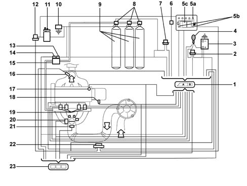
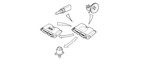
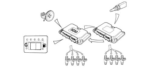
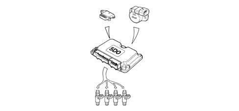
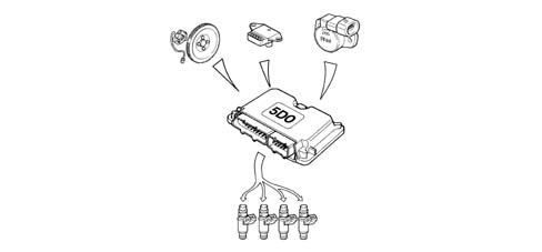
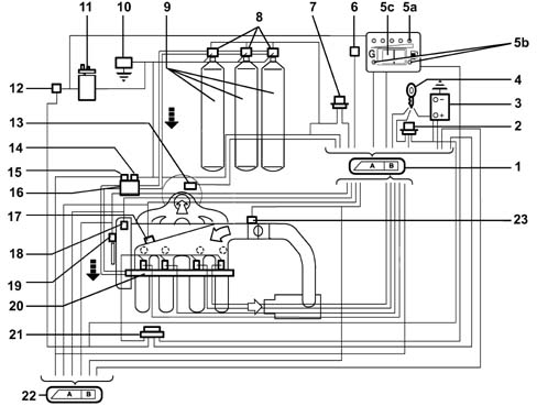
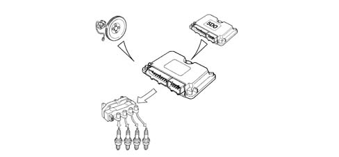
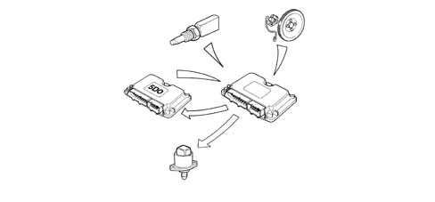
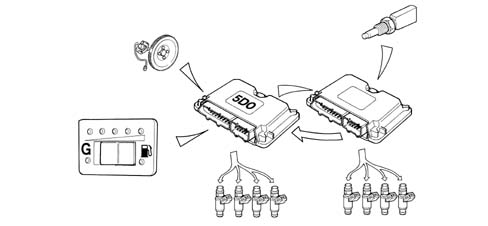
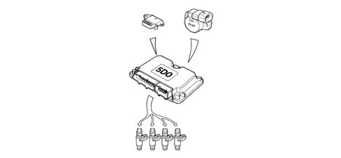
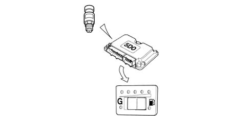
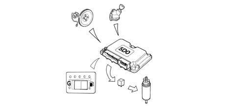
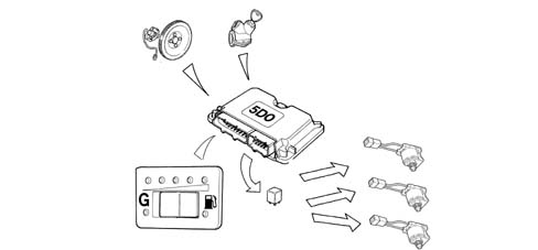
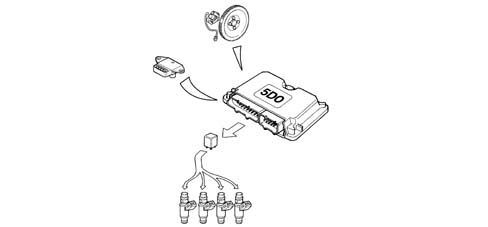
The system for running on two types of fuel comprises the Magneti Marelli IAW 48P2 system for petrol operation and the Metatron METAFUEL 5D0 system for operating on CNG. The two systems are connected via a high speed CAN line.The Magneti Marelli IAW 48P2 system belongs the category of systems integrated with:inductive discharge, digital, electronic ignitionstatic advancesequential, phased type electronic injection (1-3-4-2).The Metatron METAFUEL 5D0 belongs the category of systems integrated with:sequential, phased type electronic injection (1-3-4-2).The CNG system is clear for the basic system for all components and the operation of the basic system is not affected in all operating conditions.The two control units share some of the system elements. This sharing is transparent to the basic system.The list of components shared by the two systems, connected in parallel, is as follows:intake manifold pressure sensor;throttle position sensorengine rpm sensor;engine timing sensor;Lambda sensor upstream of the catalytic converterThe list of additional components for the methane system is as follows:electronic injection unit for METAFUEL 5D0;CNG pressure sensor on the pressure reduction unit casing; CNG cut out solenoid valve relay on the canisters;CNG cut out solenoid valves on the canisters;solenoid valve and pressure reduction unit;CNG / petrol switch (SEDIMO);CNG injector relay;injectors;petrol pump cut out relay;1 - Methane engine management control unit;2 - Injection system relay;3 - Battery;4 - Ignition switch;5a - CNG residual pressure gauge (SEDIMO)5b - Two LEDs - "petrol mode" (yellow-amber) and "gas mode" (green) (SEDIMO)6 - Diagnostic tester connection7 - Methane solenoid valve relay (on canisters and on pressure reduction unit)8 - Solenoid valves on canisters9 - Methane canisters10 - Inertia switch11 - Petrol pump12 - Petrol pump cut out relay13 - Solenoid valve on pressure reduction unit14 - Methane pressure sensor15 - Methane pressure reduction unit16 - Lambda sensor upstream of the catalyzer17 - Engine timing sensor18 - RPM and TDC sensor19 - Methane manifold and injectors20 - Throttle valve position sensor21 - Absolute pressure sensor22 - Injector relay23 - Petrol engine management control unit5c- Petrol or methane operating mode selector (SEDIMO)
OPERATION
The system is configured to normally run on methane. The two control units are always supplied whilst the engine is running.Methane/petrol switching can take place:by means of a manual control on the mode selector (SEDIMO) located in the dashboard.automatically when ordered by the methane engine management control unit if the methane in the tank has run out (pressure in the canister less than 11 bar) or in the recovery condition when methane operation is not advisable.The operating mode is signalled by means of the PETROL operation warning light (POWER MODE) in the sedimo component. Irrespective of the switch position, this indicator shows the operating mode - methane (green) or petrol (orange) by means of the two LEDs in the selector.
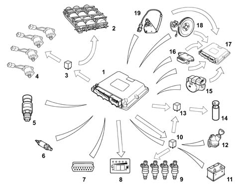
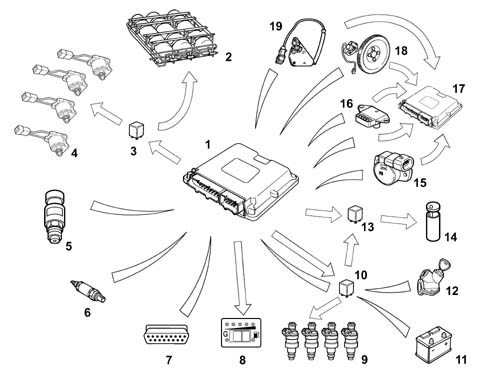
Diagram showing information entering/leaving the control unit
The communcation between the petrol engine management control unit and the CNG engine management control unit takes place via the CAN line.1 - Methane engine management control unit2 - Methane canisters3 - CNG pump and CNG solenoid valve relay (on the tank and on the pressure regulator)4 - CNG cut out solenoid valves5 - CNG pressure sensor on pressure regulator6 - Lambda sensor upstream of the catalytic converter7 - Diagnostic tester connection8 - Petrol or CNG operating mode selector with built-in operating mode indicator and pressure gauge9 - CNG injectors10 - CNG injector relay11 - Battery12 - Ignition switch13 - Petrol pump cut out relay14 - Petrol pump15 - Throttle valve position sensor16 - Air pressure sensor17 - Petrol engine management control unit18 - Rpm and TDC sensor19 - Engine timing sensor
OPERATING LOGICS
Petrol operation
In this operating mode there are no functional variations in relation to the basic system.The Magneti Marelli 48P2 basic electronic unit does not alter its behaviour and the system management strategies are the same as for the basic version.The specific elements for the CNG system do not interfere in any way with the basic system.
Methane operation
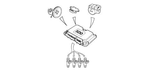
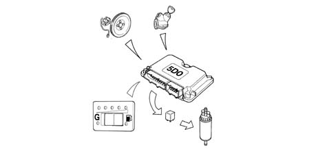
The engine runs on CNG after starting which always takes place using petrol (obviously with the selector positioned to CNG mode before starting). The petrol pump is deactivated during CNG operation, except during starting, for a period of a few seconds, corresponding to the activation of the CNG injection, necessary in order to be able to carry out the fault diagnosis of the deactivation relay.The METAFUEL 5D0 electronic unit manages the sequential, phased type injection of the CNG, the activation of the CNG cut out solenoid valves and the deactivation of the petrol pump. All the other engine management functions, including the ignition advance, are left to the basic unit. Injection takes place directly through the operation of the specific CNG system injectors. The ignition advance is adjusted by sending the basic electronic unit the advance variation to be added to the one for petrol operation. This communication takes place via the CAN line between the two control units. The other basic electronic unit functions are carried out normally and all the input signals remain unchanged. All the commands are implemented as usual (stepper, ignition, etc.).The METAFUEL 5D0 electronic unit processes the information coming from the basic system sensors, that coming via the CAN line from the 48P2 control unit and the information coming from the additional sensors for CNG operation in order to recognize the system operating conditions and produce suitable commands for the CNG injectors.The activation of the CNG cut out solenoid valves and the deactivation of the petrol pump takes place when switching from petrol to methane. When switching from methane to petrol, the METAFUEL 5D0 electronic unit operates in the opposite way to previously (i.e. it deactivates the CNG cut out solenoid valves and reactivates the petrol pump). In this case the petrol pump is switched on immediately to pressurize the system.The management strategies use typical curves and control parameters stored in the METAFUEL 5D0 electronic unit memory. The calibration figures are defined on the basis of performance, consumption, emission and driveability aims.The specific management strategies for the CNG system are basically as follows:Engine Signal ManagementIgnition managementInjection managementIdle speed managementStart-upOperation during acceleration and decelerationCut-off operationOperation in full load conditionsProtection beyond revsBarometric correctionFuel vapour recoveryControl of combustion gases - Pre-catalyzer Lambda sensorAir conditioning compressor connectionResidual fuel pressure signalPetrol pump operation;Methane solenoid valve operation;Methane injector operation;Switching between two operating modes (petrol and methane)Connection with electronic key (Fiat CODE)System self-diagnosis
Engine Signal Management
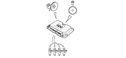
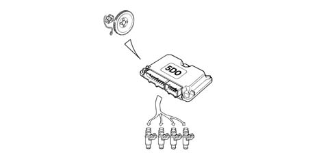
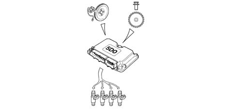
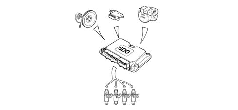
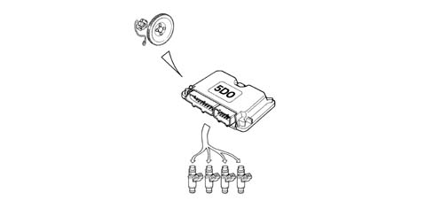
The METAFUEL 5D0 electronic unit recognizes the engine timing and determines the injection timing angle. This recognition takes place by processing the signals coming from the timing sensor and from the rpm and TDC sensor. These two signals make up the engine signals.
Ignition management
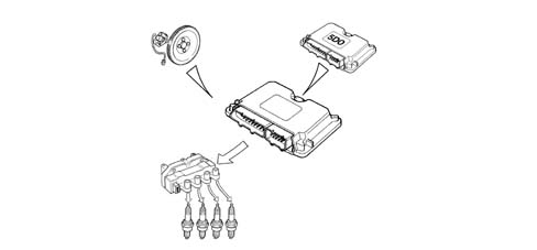
The coil charging time and the moment of ignition in relation to TDC are always determined and managed by the basic electronic unit which receives the variation in the advance to be implemented from the METAFUL 5D0 via the CAN.The METAFUEL 5D0 electronic unit memory contains a map of the advance shift values according to the engine speed and load conditions. The calculation of the advance correction involves selecting a basic value and correcting in according to the coolant temperature.
Injection management
The aim of the fuel management is to supply the correct amount of fuel required by each cylinder to satisfy the objectives of performance, consumption and engine emissions. The METAFUEL 5D0 unit does not manage the starting stage.The injection is the sequential, phased type.The METAFUEL 5D0 control unit uses an indirect type engine load measurement system (speed-density). This method is used to calculate the quantity of fuel to inject into each cylinder for each engine cycle.The methane is supplied by modulating the injector opening time. The injector inlet pressure is established by the pressure reduction unit.
Idle speed management
The idle speed management (stepper management) is carried out by the basic electronic unit; the METAFUEL 5D0 unit modifies the idle speed by means of a suitable offset transmitted via the CAN.
Start-up
The engine is always started up on petrol.
Operation during acceleration and deceleration
These operating conditions are identified by means of the throttle position and manifold pressure signals.During these two stages the METAFUEL 5D0 unit adjusts the fuel injection as quickly as possible in order to maximize acceleration torque and ensure optimum driveability during deceleration.
CUT-OFF operation
The fuel cut off strategy is implemented when the throttle is closed at high engine speeds. This strategy is only enabled above a certain coolant temperature level. The METAFUEL 5D0 electronic unit manages the inlet and outlet from this stage in order to reduce emissions during these engine operating conditions.
Operation in full load conditions
Full load opeartion is managed by the METAFUEL 5D0 electronic unit with air/CNG mixture enrichment strategies that are similar to those for petrol engine management systems.
Protection beyond revs
The METAFUEL 5D0 electronic unit manages the protection of the engine outside of revs. This protection involves cutting off the injection when a given speed is exceeded. Normal injection is resumed when the speed returns to below the critical value.
Barometric correction
There is a strategy in the METAFUEL 5D0 control unit that recognizes the altitude and implements a barometric correction of the mixture strength.
Control of combustion gases - pre-catalyzer Lambda sensor
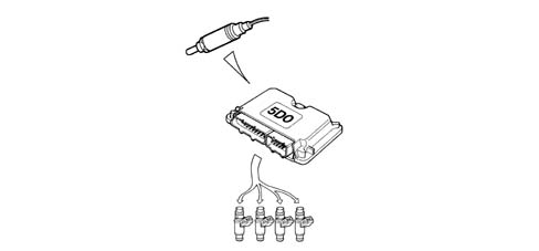
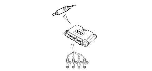
The METAFUEL 5D0 electronic unit uses the signal for the Lambda sensor upstream of the catalyzer to control the metering of the air/CNG mixture in order to ensure maximum catalyzer conversion efficiency.The METAFUEL 5D0 electronic unit manages the heaters for the two Lambda sensors, via the CAN, located upstream and downstream of the catalyzer.
Air conditioning compressor connection
The METAFUEL 5D0 electronic unit is not connected to the air conditioning system.The switching on and off of the compressor in certain operating conditions to improve the performance of the engine is managed by the basic electronic unit through the same modes and operating conditions as for the basic system.
Residual fuel pressure signal
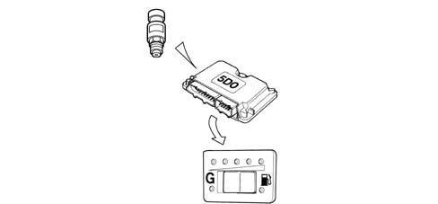
The METAFUEL 5D0 electronic unit receives the canister residual pressure signal from the CNG pressure sensor fitted on the pressure reduction unit. This information is then sent by the METAFUEL 5D0 control unit to the special indicator on the left of the instrument panel.
Petrol pump operation
The petrol pump is closed to earth by the inertia switch and is operated by the METAFUEL 5D0 electronic unit via a special relay.The petrol pump is stopped:if there is a petrol/methane switch;if the inertia switch has gone off.When switching from CNG to petrol the METAFUEL 5D0 electronic unit immediately reactivates the petrol pump to pressurize the system.
Methane cut out solenoid valve operation
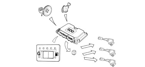
There are 4 CNG cut out solenoid valves:1 solenoid valve fitted on each canister (3 in number);1 solenoid valve fitted on the pressure reduction unit.The 2 solenoid valves are connected to one another in parallel, closed to earth by the inertia switch and operated by the METAFUEL 5D0 electronic unit by means of a special relay. The solenoid valves are closed:if the engine speed goes below a certain level;after a certain time with the key ON without the engine being started up (timed enablement);if there is a CNG/petrol switch;if the inertia switch has gone off.After the CNG/petrol switch, the METAFUEL 5D0 electronic unit deactivates the CNG cut out solenoid valves.
Methane injector operation
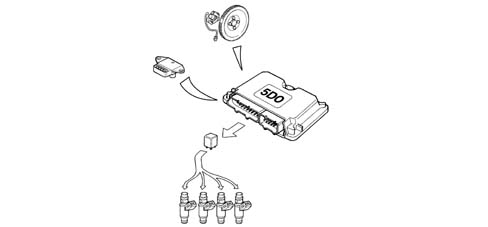
The operation of the CNG injectors is the phased sequential type.The injector timing varies according to the engine speed and the intake air pressure in order to improve the cylinder filling with benefits in terms of consumption, driveability and pollution.The injectors receive an electrical supply via a specific relay: the CNG engine management control unit closes the contacts for the appropriate part of the CNG injectors according to the situation
Switching between two operating modes (petrol and methane)
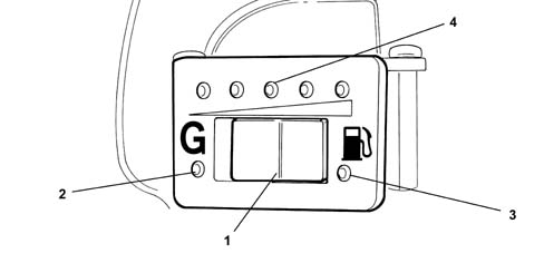
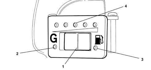
This function is regulated by the METAFUEL 5D0 electronic unit and by a switch built into the component (SEDIMO).Position "G" of the selector (1) indicates the choice to run on gas (green LED on) (2), whilst running on petrol is indicated by the amber yellow LED lit up (3). There is also a residual pressure gauge (4) consisting of a series of green LEDs + 1 yellow LED for the reserve condition. This indicator is activated when the last LED is on and the reserve condition exists.1 - Operating mode switch2 - Green LED (methane operation)3 - Amber/yellow LED (petrol operation)4 - Residual pressure gaugeThe lighting up logic for the "petrol mode" indicator in the SEDIMO component is, irrespective of the selector switch position, to signal:a) CNG operation = green LED onb) petrol operation = amber yellow LED onThe switching between the two operating modes, when instructed by the user, can take place at any time, but only when the engine speed is below a certain level.The pressure of the CNG in the canisters is utilized in identifying the "empty canisters" condition for the automatic return to petrol operation. As a result of the canisters being drained, the pressure in the rail decreases rapidly to below a certain level.Switching from petrol to methaneThe following cases are possible:1. Manually, by the user with the engine switched offSelector switch position: methane gas"PETROL mode" LED lit up:During starting the "petrol mode" LED is on (activated), thereby indicating that the engine is supplied with petrol. When the engine has been started up (as soon as cranking is over) the switch to methane takes place and the "methane mode" warning light lights upSwitching to CNG is prevented if the pressure of the methane is below a level corresponding to the "empty canister" situation, if the engine coolant temperature is too low or if a fault has been located in the system.2. Manually, by the user with the engine running.Selector switch initial position: petrol"PETROL mode" LED initially coming onBy selecting the methane mode the user starts the petrol to CNG switching function which only takes place when the following conditions are satisfied:CNG canister pressure above a certain level;engine coolant temperature above a certain level;no faults detected during the fault diagnosis of the METAFUEL 5D0 electronic unit.The switching does not take place unless all the conditions are satisfied. When the switching has taken place the "methane mode" LED in the SEDIMO device is lit up.Switching from methane to petrolThe following cases are possible:1. Automatically (with the engine running).Initial selector position: "methane mode"."Methane mode" LED initially coming onThe automatic switching from methane to petrol takes place according to decisions by the METAFUEL 5D0 unit control strategies and only if the following operating conditions are satisfied:methane pressure below a certain level;identification of a fault in the systemIf one of the conditions has been satisfied, the switching from CNG to petrol takes place immediately and the "petrol mode" LED in the SEDIMO device lights up. The position of the selector remains unchanged.After the switching has taken place, CNG operation is completely inhibited until the cause of the automatic switching is eliminated (fuel supply or elimination of the fault).2. Manually, by the user with the engine running.This operation is only permitted if the engine speed is below a certain level"Methane mode" selector initial position"Petrol mode" LED initial coming on.When switching to the petrol mode the user starts the switching function from CNG to petrol which takes place immediately together with the "petrol mode" indicator in the SEDIMO component coming on.
Connection with electronic key
The METAFUEL 5D0 control unit is not connected to the electronic key control unit (Fiat CODE).The electronic key system only maintains its operation with the basic system; therefore, in order to be able to switch to methane, it is necessary to receive the go ahead from the petrol control unit and this go ahead is given if the check with the Fiat CODE is okay and the operation with the electronic key is guaranteed in all conditions.Starting with a key that has not been memorized in the electronic key control unit is not permitted in either operating mode (petrol or CNG). The procedure for personalizing the vehicle or programming the keys is the same and should be carried out in the petrol mode.
System self-diagnosis
The METAFUEL 5D0 electronic unit carries out the fault diagnosis of the input/output, cyclically checking the signals and an internal self-diagnosis programmes the codes in the EEPROM in the case of malfunctions (passive self-diagnosis).It is also possible to activate the individual actuators, using the diagnostic equipment, checking their efficiency (active self-diagnosis).The total cancellation of the EEPROM is carried out by means of the diagnostic equipment.If there is a fault, the control unit manages the alternative functions to keep the engine running where possible to allow the vehicle to reach a service centre or, in more serious cases, it automatically switches the system to petrol operation, switching off the residual pressure indicator in the SEDIMO device (recovery).
PASSIVE SELF-DIAGNOSIS
The METAFUEL 5D0 electronic unit carries out the fault diagnosis of the input/output, cyclically checking the signals and in the case of malfunctions, programming the codes in the EEPROM (passive self-diagnosis). The fault diagnosis carried out and the recovery actions in the case of a fault in the following components are reported:
Manifold pressure sensor
The METAFUEL 5D0 electronic unit carries out the following electrical fault diagnosis on the signal coming from the manifold pressure sensor every 4 ms:short circuit to earth;short circuit to Vbattery or open circuit.If a fault is detected, the control unit implements the following recovery actions:return to petrol operating mode and switching on "petrol mode" indicator in the mode selector;warning light in instrument panel lit up.
Throttle position sensor
The METAFUEL 5D0 electronic unit carries out the following electrical fault diagnosis on the signal coming from the throttle position sensor every 4 ms:short circuit to earth;short circuit to Vbattery or open circuit.If a fault is detected, the control unit implements the following recovery actions:return to petrol operating mode and switching on "petrol mode" indicator in the mode selector;warning light in instrument panel lit up.
Methane pressure sensor
The METAFUEL 5D0 electronic unit carries out the following electrical fault diagnosis on the signal coming from the CNG pressure sensor cyclically:Short circuit to earth;Short circuit to Vbattery or open circuit.If a fault is detected, the control unit implements the following recovery actions, but only if there is a short circuit to earth:Return to petrol operating mode and switching on "petrol mode" indicator in the instrument panel;Switching on of the selector warning light;The pressure indicator in the SEDIMO is off.
CAN line
The METAFUEL 5D0 electronic unit cyclically carries out a functional diagnosis on the CAN line to check for a break in the connection.If a fault is detected, the control unit implements the following recovery actions:return to petrol operating mode and switching on "petrol mode" indicator in the instrument panel for each individual break. Return to CNG operating mode when the connection is restored, switching off the "petrol mode" indicator in the instrument panel;definitve return to petrol operating mode and then switching on of the "petrol mode" indicator in the instrument panel after 5 interruptions in a single trip and switching on of the warning light in the instrument panel.
Pre-catalyzer Lambda sensor
The METAFUEL 5D0 electronic unit cyclically carries out a functional fault diagnosis signalling that the Lambda sensor is not working properly in the case of a fault or malfunction.If a fault is detected, the control unit implements the following recovery actions:disabling closed-loop mixture strength check;inhibition of self-adjustment strategies.
Rpm sensor
The METAFUEL 5D0 electronic unit checks the accuracy of the counting of the impulses coming from the rpm sensor facing the flywheel with 58 teeth, signalling if there is a fault or malfunction:signal not present.If a fault is detected, the control unit implements the following recovery actions:resynchronization;the vehicle does not move or cuts out.
Timing sensor
The METAFUEL 5D0 electronic unit cyclically carries out a fault diagnosis on the timing sensor signalling the following in the case of a fault or malfunction:signal not plausible.There are no recovery actions planned, the system will operate at 360 degrees with the correct or incorrect timing.
Methane injectors
The METAFUEL 5D0 electronic unit cyclically carries out an electrical fault diganosis on the CNG injectors signalling the following problems:injector cold side open circuit;injector cold side short circuit to earth;injector cold side short circuit to Vbattery.If a fault is detected, the control unit implements the following recovery actions:return to petrol operating mode;warning light in instrument panel lit up.
Methane injector relay
The METAFUEL 5D0 electronic unit cyclically carries out an electrical fault diganosis on the CNG injector relay coil every 131 ms, signalling the following problems:short circuit to earth or open circuit. this fault diagnosis is only possible in the petrol operating mode;short circuit to Vbattery: this fault diagnosis is only possible in the CNG operating mode.If a fault is detected, the control unit implements the following recovery actions:return to petrol operating mode;warning light in instrument panel lit up.
CNG cut out solenoid valve relay
The METAFUEL 5D0 electronic unit cyclically carries out an electrical fault diganosis on the CNG cut out solenoid valve relay coil every 131 ms, signalling the following problems:short circuit to earth or open circuit: this fault diagnosis is only possible in the petrol operating mode;short circuit to Vbattery: this fault diagnosis is only possible in the methane operating mode.If a fault is detected, the control unit implements the following recovery actions:return to petrol operating mode;warning light in instrument panel lit up.
Petrol pump cut out relay
The METAFUEL 5D0 electronic unit cyclically carries out an electrical fault diganosis on the petrol pump cut out solenoid valve relay coil every 131 ms, signalling the following problems:short circuit to earth or open circuit: this fault diagnosis is carried out, in CNG operating mode, once only during starting on petrol and then switching to CNG;short circuit to Vbattery: this fault diagnosis is possible in both CNG and petrol operating modes.There are no recovery actions.
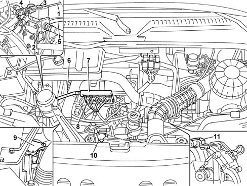
LOCATION OF BIPOWER SYSTEM COMPONENTS IN ENGINE COMPARTMENT
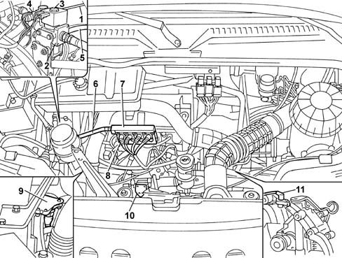
The diagram below illustrates the location of the bipower system components on the vehicle1 - Methane high pressure pipe2 - Pressure reduction unit3 - Methane cut out solenoid valve4 - Methane pressure sensor5 - Engine coolant circulation pipes inside pressure reduction unit6 - Methane low pressure pipe7 - Methane distribution manifold to injectors8 - Methane injectors9 - Intake manifold absolute pressure sensor10 - Throttle position sensor11 - Engine rpm and TDC sensor
Methane pressure sensor
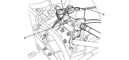
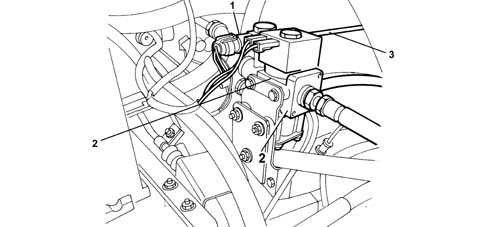
The pressure sensor (1) is fitted on the pressure reduction unit (2) at the high pressure line intake (3).The diagram below illustrates the location of the sensor on the pressure reduction unit.The function of the sensor on the methane high pressure line is to:Indicate the amount of methane in the canisters (petrol/methane switching selector LED).provide information for the control unit for the automatic switching from methane operation to petrol operation if the methane pressure is too low (below 15 bar).
Operation
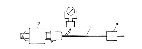
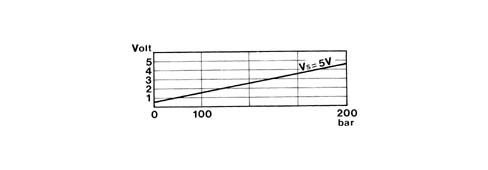
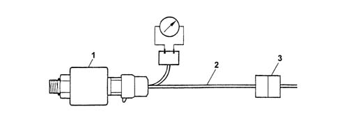
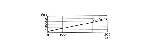
It is a capacitive type sensor (where the sensitive element consists of two gold-plated ceramic discs) which contains the signal air conditioning circuit. It receives a supply voltage of 5V.Wiring connectorThe sensor pin out is illustrated in the diagram.B19 - EarthB12 - Power supplyB4 - output signalThe numbers in the boxes indicate the CNG control unit terminals.The electrical check is carried out by placing a bridge (2) to be constructed in situ (not supplied as spares) between the sensor (1) and the connector (3) in order to supply the sensor and receive the output signal using a multimeter (voltmeter).1 Close the methane cut out tap (valve unit in luggage compartment).2 Place the bridge between the sensor and the connector.3 Detach the sensor and check that the output voltage is 500 mV4 The end of scale check involves filling the methane canister and checking that the sensor output voltage is approximately 4.5 Volt (this should be the reading at a pressure of 200 bar which corresponds to the canister being completely full).
Rpm and TDC sensor
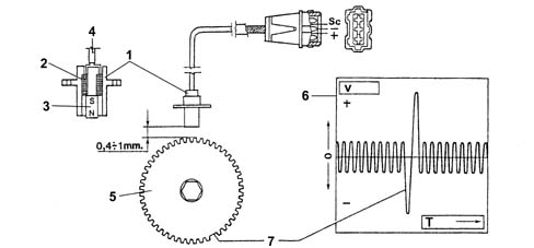
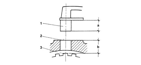
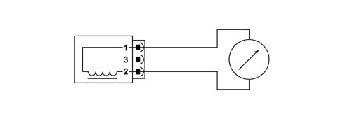
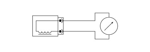
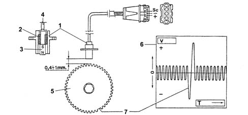
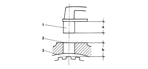
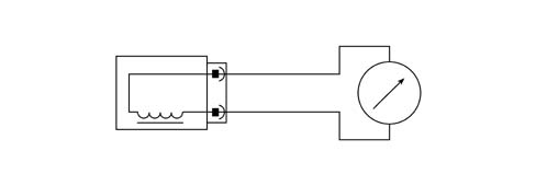
The rpm sensor (1) gives a reference for the angular position of the crankshaft (TDC identification). It is secured to the gearbox bell housing and faces the phonic wheel. (see diagram)1 - Rpm and TDC sensor2 - Electrical winding3 - Permanent magnet4 - Twisted cable (40 turns/metre with anti-interference sheath (SC)5 - Flywheel with (60 - 2) 58 teeth on engine flywheel6 - Progress of inductive signal produced7 - Variation in the signal due to the missing 2 teeth or timing referenceThis consists of a sealed tubular case containing a permanent magnet (3) and an electric winding or copper coil (2). It is connected to the electronic control unit via terminals 11 and 28.The cables are twisted (40 turns/metre) and covered by an anti-interference sheath connected to earth. A heat-resistant PVC sheath covers leads and shielding.The flywheel (5) comprises 58 teeth plus one space equivalent to the size of the two missing teeth (7). The reference defined by the space for the two missing teeth constitutes the basis for detecting the point of synchronism (TDC).The synchronism point is recognised at the end of the first tooth (8) following the gap left by the two missing teeth: when this passes beneath the sensor, the crankshaft is located with piston pair 1-4 at 114° before TDC.Operation is as follows: The sensor permanent magnetic field (3) affects the winding (2) and also the phonic wheel (5) teeth. In practice, when the tooth is in front of the sensor, the magnetic flow is maximum. When the gap passes, the flow is minimum. During phonic wheel (5) rotation, whenever a tooth tends to approach the sensor, the signal rises toward the positive voltage value (+). It becomes zero during the tooth-sensor alignment stage and passes through a negative voltage value (-) as the tooth moves away.The graph and the waveform (6) (which corresponds to the mechanical position of the phonic wheel) is an e.m.f. set up in the sensor winding and may range from a few volts at low rpm to several tens of volts at a high rpm. Because the resulting voltage depends on the distance between sensor core and tooth tip, it is extremely important that this height, known as the GAP is between 0.5 +1.5 mm.The train of analogue signals (diagram 6) generated by the sensor (1) is sent to an appropriate converter circuit (A/D analogue digital) in the electronic control unit (ECU) and used for:Calculating the engine rpm;Calculating the optimal ignition advance.Wiring connectorThe connector pin out is illustrated in the diagram.The sensor is connected to the CNG control unit (terminals A17 and A18) by means of twisted cables covered in an anti-interference sheath connected to earth.As the sensor is in series to the two control units, the CNG control unit input signal leaves via terminals A7 and A8 (unchanged if the engine is running on petrol, suitably treated, on the other hand, if the engine is running on methane) and reaches terminals 28 and 11, respectively, of the basic control unit.Checking the gapThe sensor is fitted in production with tolerances that ensure a gap of 0.5 - 1.5 mm without the need for further adjustments. (see diagram)1 - Sensor2 - Fitting plane3 - Phonic wheel toothThis gap is also guaranteed if a replacement sensor is fitted. However, if a check needs to be carried out, proceed as follows:measure the distance between the end of the sensor and the lower part of the sensor bracket (distance "a")measure the distance between the fitting plane on the gearbox and the upper part of the tooth (distance "b").The gap (t = b-a) should be between 0.5 and 1.5 mm.Checking the resistanceSensor resistance may be measured by disconnecting the connector and connecting an ohmmeter at the sensor terminals.The resistance control circuit is illustrated in the diagram (Resistance: 1134 - 1386 Ohm at 20 °C.)
METAFUEL 5D0 INJECTION CONTROL UNIT
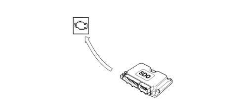
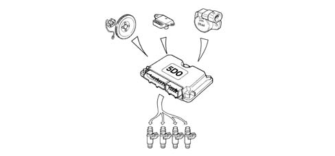
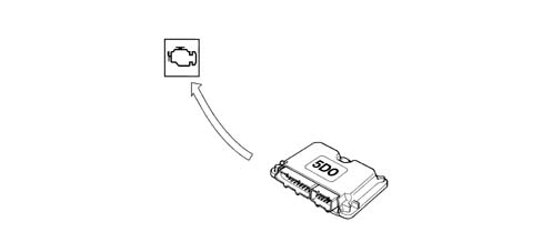
The control unit is fitted under the passenger seat and is capable of withstanding high temperatures.It is a digital type unit with a microprocessor featuring a high calculation capacity and is accurate, reliable, versatile, with low energy consumption and is maintenance-free.The task of the electronic control unit is to process the signals coming from the additional sensors belonging to the CNG system, the signals for the sensors shared with the petrol system and the information coming from the Magneti Marelli 48P2 control unit through the application of software algorithms and to control the operation of the actutators (in particular the CNG injectors and CNG cut out solenoid valves) in order to ensure the optimum operation of the engine.
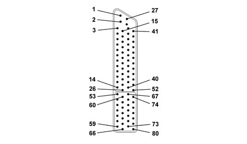
METAFUEL 5D0 control unit pin out
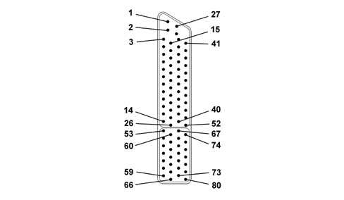
The diagram below shows the control unit pin out.1 - Direct supply from the battery2 - Not connected3 - Diagnostic socket (line K - TX)4 - Not connected5 - Not connected6 - Not connected7 - Not connected8 - Not connected9 - Not connected10 - GAS mode signal11 - Timing sensor (negative)12 - Timing sensor (positive)13 - Not connected14 - Not connected15 - Diagnostic socket (line L - RX)16 - Outside sensor supply17 - Not connected18 - Not connected19 - Not connected20 - Not connected21 - Not connected22 - Digital earth23 - CAN-L line24 - Not connected25 - Not connected26 - Not connected27 - Battery earth direct return28 - Radiofrequency earth29 - Not connected30 - GAS pressure sensor signal31 - Not connected32 - Throttle position sensor (negative)33 - Absolute pressure sensor (negative)34 - Supply controlled by ignition (+15)35 - Pre-catyalyzer Lambda sensor signal (negative)36 - Not connected37 - Not connected38 - CAN-H line39 - Not connected40 - Not connected41 - Not connected42 - Not connected43 - Throttle position sensor signal (positive)44 - Absolute pressure sensor signal45 - Not connected46 - Pre-catyalyzer Lambda sensor signal47 - Petrol or methane GAS operation selector input48 - Not connected49 - Not connected50 - Not connected51 - VRS rpm sensor (positive)52 - VRS rpm sensor (negative)53 - Not connected54 - GAS cut out solenoid valves relay feed55 - Battery earth56 - Cylinder no. 4 injector.57 - Cylinder no. 2 injector.58 - Not connected59 - CNG injector supply return (INJ+)60 - CNG level analogue signal output61 - Battery earth62 - Battery earth63 - Cylinder no. 3 injector.64 - Cylinder no. 1 injector.65 - Not connected66 - CNG injector supply return67 - Not connected68 - GAS injector relay feed69 - Not connected70 - Not connected71 - Not connected72 - Not connected73 - Not connected74 - Petrol pump deactivating relay feed75 - Not connected76 - Battery earth77 - Not connected78 - Not connected79 - Not connected80 - CNG injector supply return (INJ+)
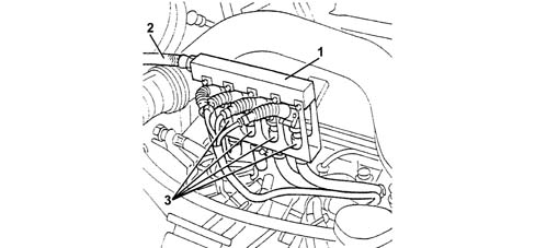
METHANE DISTRIBUTION MANIFOLD
The methane distribution unit is illustrated in the diagram belowThe methane distribution manifold (1) is fastened by means of a special bracket to the tappet cover and to the cylinder head. It receives methane at low pressure from the flexible pipe (2) which acts as a connection with the pressure reduction unit and distributes it to the four injectors (3).
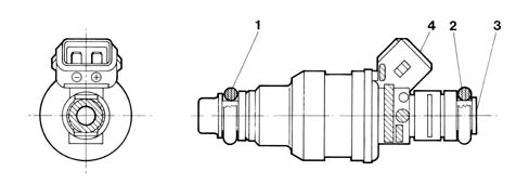
METHANE INJECTORS
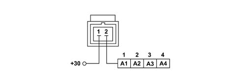
The special methane injectors (shown in the diagram) are the sonic type supplied by Bosch.The main difference between these injectors and those for petrol lies in the fact that they have a larger nozzle for the methane outlet and operate at a considerably higher pressure (9 ± 1 bar). As a result, the quantity of methane injected depends solely on the injector opening time (injection time) which is established by the CNG electronic control unit. Since the pressure downstream of the injector is irrelevant, there is no need to fit a pressure differential regulator like on petrol systems.The injector operating logic is the "phased, sequential" type, in other words the four injectors are operated individually depending on the engine cylinder inlet sequence, whilst the supply for each cylinder can already begin during the expansion stroke until the inlet stroke has already started.The injectors are fastened by two injector holder brackets, one upper one and one lower one which keep them in position; two rubber seals (1) and (2) ensure the seal for the two half brackets.The two injector holders are secured to one another and to the tappet cover and the cylinder head; there are rubber gas pipes from each injector to the methane introduction nozzles located on each inlet duct.The pipes are fastened to the injectors and to the nozzles by bands.The methane supply takes place at the top part (3) of the injector (top feed); the connector for the injector operation engages in the housing (4).Connector Pin OutThe connector pin out is illustrated in the diagramChecking the resistanceInjector resistance may be measured by disconnecting the connector and connecting an ohmmeter as shown in the figure. The reading should be 4.6 Ohm.
Engines: 2.0 16V
Ignition management
The coil charging time and the moment of ignition in relation to TDC are always determined and managed by the basic electronic unit which receives the variation in the advance to be implemented from the METAFUL 5D0 via the CAN.The METAFUEL 5D0 electronic unit memory contains a map of the advance shift values according to the engine speed and load conditions. The calculation of the advance correction involves selecting a basic value and correcting in according to the coolant temperature.
Injection management
The aim of the fuel management is to supply the correct amount of fuel required by each cylinder to satisfy the objectives of performance, consumption and engine emissions. The METAFUEL 5D0 unit does not manage the starting stage.The injection is the sequential, phased type.The METAFUEL 5D0 control unit uses an indirect type engine load measurement system (speed-density). This method is used to calculate the quantity of fuel to inject into each cylinder for each engine cycle.The methane is supplied by modulating the injector opening time. The injector inlet pressure is established by the pressure reduction unit.
Idle speed management
The idle speed management (stepper management) is carried out by the basic electronic unit; the METAFUEL 5D0 unit modifies the idle speed by means of a suitable offset transmitted via the CAN.
Start-up
The engine is always started up on petrol.
Operation during acceleration and deceleration
These operating conditions are identified by means of the throttle position and manifold pressure signals.During these two stages the METAFUEL 5D0 unit adjusts the fuel injection as quickly as possible in order to maximize acceleration torque and ensure optimum driveability during deceleration.
CUT-OFF operation
The fuel cut off strategy is implemented when the throttle is closed at high engine speeds. This strategy is only enabled above a certain coolant temperature level. The METAFUEL 5D0 electronic unit manages the inlet and outlet from this stage in order to reduce emissions during these engine operating conditions.
Operation in full load conditions
Full load opeartion is managed by the METAFUEL 5D0 electronic unit with air/CNG mixture enrichment strategies that are similar to those for petrol engine management systems.
Protection beyond revs
The METAFUEL 5D0 electronic unit manages the protection of the engine outside of revs. This protection involves cutting off the injection when a given speed is exceeded. Normal injection is resumed when the speed returns to below the critical value.
Barometric correction
There is a strategy in the METAFUEL 5D0 control unit that recognizes the altitude and implements a barometric correction of the mixture strength.
Control of combustion gases - pre-catalyzer Lambda sensor
The METAFUEL 5D0 electronic unit uses the signal for the Lambda sensor upstream of the catalyzer to control the metering of the air/CNG mixture in order to ensure maximum catalyzer conversion efficiency.The METAFUEL 5D0 electronic unit manages the heaters for the two Lambda sensors, via the CAN, located upstream and downstream of the catalyzer.
Air conditioning compressor connection
The METAFUEL 5D0 electronic unit is not connected to the air conditioning system.The switching on and off of the compressor in certain operating conditions to improve the performance of the engine is managed by the basic electronic unit through the same modes and operating conditions as for the basic system.
Residual fuel pressure signal
The METAFUEL 5D0 electronic unit receives the canister residual pressure signal from the CNG pressure sensor fitted on the pressure reduction unit. This information is then sent by the METAFUEL 5D0 control unit to the special indicator on the left of the instrument panel.
Petrol pump operation
The petrol pump is closed to earth by the inertia switch and is operated by the METAFUEL 5D0 electronic unit via a special relay.The petrol pump is stopped:if there is a petrol/methane switch;if the inertia switch has gone off.When switching from CNG to petrol the METAFUEL 5D0 electronic unit immediately reactivates the petrol pump to pressurize the system.
Methane cut out solenoid valve operation
There are 4 CNG cut out solenoid valves:1 solenoid valve fitted on each canister (3 in number);1 solenoid valve fitted on the pressure reduction unit.The 2 solenoid valves are connected to one another in parallel, closed to earth by the inertia switch and operated by the METAFUEL 5D0 electronic unit by means of a special relay. The solenoid valves are closed:if the engine speed goes below a certain level;after a certain time with the key ON without the engine being started up (timed enablement);if there is a CNG/petrol switch;if the inertia switch has gone off.After the CNG/petrol switch, the METAFUEL 5D0 electronic unit deactivates the CNG cut out solenoid valves.
Methane injector operation
The operation of the CNG injectors is the phased sequential type.The injector timing varies according to the engine speed and the intake air pressure in order to improve the cylinder filling with benefits in terms of consumption, driveability and pollution.The injectors receive an electrical supply via a specific relay: the CNG engine management control unit closes the contacts for the appropriate part of the CNG injectors according to the situation
Switching between two operating modes (petrol and methane)
This function is regulated by the METAFUEL 5D0 electronic unit and by a switch built into the component (SEDIMO).Position "G" of the selector (1) indicates the choice to run on gas (green LED on) (2), whilst running on petrol is indicated by the amber yellow LED lit up (3). There is also a residual pressure gauge (4) consisting of a series of green LEDs + 1 yellow LED for the reserve condition. This indicator is activated when the last LED is on and the reserve condition exists.1 - Operating mode switch2 - Green LED (methane operation)3 - Amber/yellow LED (petrol operation)4 - Residual pressure gaugeThe lighting up logic for the "petrol mode" indicator in the SEDIMO component is, irrespective of the selector switch position, to signal:a) CNG operation = green LED onb) petrol operation = amber yellow LED onThe switching between the two operating modes, when instructed by the user, can take place at any time, but only when the engine speed is below a certain level.The pressure of the CNG in the canisters is utilized in identifying the "empty canisters" condition for the automatic return to petrol operation. As a result of the canisters being drained, the pressure in the rail decreases rapidly to below a certain level.Switching from petrol to methaneThe following cases are possible:1. Manually, by the user with the engine switched offSelector switch position: methane gas"PETROL mode" LED lit upDuring starting the "petrol mode" LED is on (activated), thereby indicating that the engine is supplied with petrol. When the engine has been started up (as soon as cranking is over) the switch to methane takes place and the "methane mode" warning light lights upSwitching to CNG is prevented if the pressure of the methane is below a level corresponding to the "empty canister" situation, if the engine coolant temperature is too low or if a fault has been located in the system.2. Manually, by the user with the engine running.Selector switch initial position: petrol"PETROL mode" LED initial coming onBy selecting the methane mode the user starts the petrol to CNG switching function which only takes place when the following conditions are satisfied:CNG canister pressure above a certain level;engine coolant temperature above a certain level;no faults detected during the fault diagnosis of the METAFUEL 5D0 electronic unit.The switching does not take place unless all the conditions are satisfied. When the switching has taken place the "methane mode" LED in the SEDIMO device is lit up.Switching from methane to petrolThe following cases are possible:1. Automatically (with the engine running).Initial selector position: "methane mode"."Methane mode" LED initial coming onThe automatic switching from methane to petrol takes place according to decisions by the METAFUEL 5D0 unit control strategies and only if the following operating conditions are satisfied:methane pressure below a certain level;identification of a fault in the systemIf one of the conditions has been satisfied, the switching from CNG to petrol takes place immediately and the "petrol mode" LED in the SEDIMO device lights up. The position of the selector remains unchanged.After the switching has taken place, CNG operation is completely inhibited until the cause of the automatic switching is eliminated (fuel supply or elimination of the fault).2. Manually, by the user with the engine running.This operation is only permitted if the engine speed is below a certain level"Methane mode" selector initial position"Petrol mode" LED initial coming on.When switching to the petrol mode the user starts the switching function from CNG to petrol which takes place immediately together with the "petrol mode" indicator in the SEDIMO component coming on.
Connection with electronic key
The METAFUEL 5D0 control unit is not connected to the electronic key control unit (Fiat CODE).The electronic key system only maintains its operation with the basic system; therefore, in order to be able to switch to methane, it is necessary to receive the go ahead from the petrol control unit and this go ahead is given if the check with the Fiat CODE is okay and the operation with the electronic key is guaranteed in all conditions.Starting with a key that has not been memorized in the electronic key control unit is not permitted in either operating mode (petrol or CNG). The procedure for personalizing the vehicle or programming the keys is the same and should be carried out in the petrol mode.
System self-diagnosis
The METAFUEL 5D0 electronic unit carries out the fault diagnosis of the input/output, cyclically checking the signals and an internal self-diagnosis programmes the codes in the EEPROM in the case of malfunctions (passive self-diagnosis).It is also possible to activate the individual actuators, using the diagnostic equipment, checking their efficiency (active self-diagnosis).The total cancellation of the EEPROM is carried out by means of the diagnostic equipment.If there is a fault, the control unit manages the alternative functions to keep the engine running where possible to allow the vehicle to reach a service centre or, in more serious cases, it automatically switches the system to petrol operation, switching off the residual pressure indicator in the SEDIMO device (recovery).
PASSIVE SELF-DIAGNOSIS
The METAFUEL 5D0 electronic unit carries out the fault diagnosis of the input/output, cyclically checking the signals and in the case of malfunctions, programming the codes in the EEPROM (passive self-diagnosis). The fault diagnosis carried out and the recovery actions in the case of a fault in the following components are reported:
Manifold pressure sensor
The METAFUEL 5D0 electronic unit carries out the following electrical fault diagnosis on the signal coming from the manifold pressure sensor every 4 ms:short circuit to earth;short circuit to Vbattery or open circuit.If a fault is detected, the control unit implements the following recovery actions:return to petrol operating mode and switching on "petrol mode" indicator in the mode selector;warning light in instrument panel lit up.
Throttle position sensor
The METAFUEL 5D0 electronic unit carries out the following electrical fault diagnosis on the signal coming from the throttle position sensor every 4 ms:short circuit to earth;short circuit to Vbattery or open circuit.If a fault is detected, the control unit implements the following recovery actions:return to petrol operating mode and switching on "petrol mode" indicator in the mode selector;warning light in instrument panel lit up.
Methane pressure sensor
The METAFUEL 5D0 electronic unit carries out the following electrical fault diagnosis on the signal coming from the CNG pressure sensor cyclically:Short circuit to earth;Short circuit to Vbattery or open circuit.If a fault is detected, the control unit implements the following recovery actions, but only if there is a short circuit to earth:Return to petrol operating mode and switching on "petrol mode" indicator in the instrument panel;Switching on of the selector warning light;The pressure indicator in the SEDIMO is off.
CAN line
The METAFUEL 5D0 electronic unit cyclically carries out a functional diagnosis on the CAN line to check for a break in the connection.If a fault is detected, the control unit implements the following recovery actions:return to petrol operating mode and switching on "petrol mode" indicator in the instrument panel foar each individual break; Return to CNG operating mode when the connection is restored, switching off the "petrol mode" indicator in the instrument panel;definitve return to petrol operating mode and then switching on of the "petrol mode" indicator in the instrument panel after 5 interruptions in a single trip and switching on of the warning light in the instrument panel.
Pre-catalyzer Lambda sensor
The METAFUEL 5D0 electronic unit cyclically carries out a functional fault diagnosis signalling that the Lambda sensor is not working properly in the case of a fault or malfunction.If a fault is detected, the control unit implements the following recovery actions:disabling closed-loop mixture strength check;inhibition of self-adjustment strategies.
Rpm sensor
The METAFUEL 5D0 electronic unit checks the accuracy of the counting of the impulses coming from the rpm sensor facing the flywheel with 58 teeth, signalling if there is a fault or malfunction:signal not present.If a fault is detected, the control unit implements the following recovery actions:resynchronization;the vehicle does not move or cuts out.
Timing sensor
The METAFUEL 5D0 electronic unit cyclically carries out a fault diagnosis on the timing sensor signalling the following in the case of a fault or malfunction:signal not plausible.There are no recovery actions planned, the system will operate at 360 degrees with the correct or incorrect timing.
Methane injectors
The METAFUEL 5D0 electronic unit cyclically carries out an electrical fault diganosis on the CNG injectors signalling the following problems:injector cold side open circuit;injector cold side short circuit to earth;injector cold side short circuit to Vbattery.If a fault is detected, the control unit implements the following recovery actions:return to petrol operating mode;warning light in instrument panel lit up.
Methane injector relay
The METAFUEL 5D0 electronic unit cyclically carries out an electrical fault diganosis on the CNG injector relay coil every 131 ms, signalling the following problems:short circuit to earth or open circuit: this fault diagnosis is only possible in the petrol operating mode;short circuit to Vbattery: this fault diagnosis is only possible in the CNG operating mode.If a fault is detected, the control unit implements the following recovery actions:return to petrol operating mode;warning light in instrument panel lit up.
CNG cut out solenoid valve relay
The METAFUEL 5D0 electronic unit cyclically carries out an electrical fault diganosis on the CNG cut out solenoid valve relay coil every 131 ms, signalling the following problems:short circuit to earth or open circuit: this fault diagnosis is only possible in the petrol operating mode;short circuit to Vbattery: this fault diagnosis is only possible in the methane operating mode.If a fault is detected, the control unit implements the following recovery actions:return to petrol operating mode;warning light in instrument panel lit up.
Petrol pump cut out relay
The METAFUEL 5D0 electronic unit cyclically carries out an electrical fault diganosis on the petrol pump cut out solenoid valve relay coil every 131 ms, signalling the following problems:short circuit to earth or open circuit: this fault diagnosis is carried out, in CNG operating mode, once only during starting on petrol and then switching to CNG;short circuit to Vbattery: this fault diagnosis is possible in both CNG and petrol operating modes.There are no recovery actions.
LOCATION OF BIPOWER SYSTEM COMPONENTS IN ENGINE COMPARTMENT
The diagram below illustrates the location of the bipower system components on the vehicle1 - Methane high pressure pipe2 - Pressure reduction unit3 - Methane cut out solenoid valve4 - Methane pressure sensor5 - Engine coolant circulation pipes inside pressure reduction unit6 - Methane low pressure pipe7 - Methane distribution manifold to injectors8 - Methane injectors9 - Intake manifold absolute pressure sensor10 - Throttle position sensor11 - Engine rpm and TDC sensor
Methane pressure sensor
The pressure sensor (1) is fitted on the pressure reduction unit (2) at the high pressure line intake (3).The diagram below illustrates the location of the sensor on the pressure reduction unit.The function of the sensor on the methane high pressure line is to:Indicate the amount of methane in the canisters (petrol/methane switching selector LED).provide information for the control unit for the automatic switching from methane operation to petrol operation if the methane pressure is too low (below 15 bar).
Operation
It is a capacitive type sensor (where the sensitive element consists of two gold-plated ceramic discs) which contains the signal air conditioning circuit. It receives a supply voltage of 5V.Wiring connectorThe sensor pin out is illustrated in the diagram.B19 - EarthB12 - Power supplyB4 - output signalThe numbers in the boxes indicate the CNG control unit terminals.The electrical check is carried out by placing a bridge (2) to be constructed in situ (not supplied as spares) between the sensor (1) and the connector (3) in order to supply the sensor and receive the output signal using a multimeter (voltmeter).1 Close the methane cut out tap (valve unit in luggage compartment).2 Place the bridge between the sensor and the connector.3 Detach the sensor and check that the output voltage is 500 mV4 The end of scale check involves filling the methane canister and checking that the sensor output voltage is approximately 4.5 Volt (this should be the reading at a pressure of 200 bar which corresponds to the canister being completely full).
Rpm and TDC sensor
The rpm sensor (1) gives a reference for the angular position of the crankshaft (TDC identification). It is secured to the gearbox bell housing and faces the phonic wheel. (see diagram)1 - Rpm and TDC sensor2 - Electrical winding3 - Permanent magnet4 - Twisted cable (40 turns/metre with anti-interference sheath (SC)5 - Flywheel with (60 - 2) 58 teeth on engine flywheel6 - Progress of inductive signal produced7 - Variation in the signal due to the missing 2 teeth or timing referenceThis consists of a sealed tubular case containing a permanent magnet (3) and an electric winding or copper coil (2). It is connected to the electronic control unit via terminals 11 and 28.The cables are twisted (40 turns/metre) and covered by an anti-interference sheath connected to earth. A heat-resistant PVC sheath covers leads and shielding.The flywheel (5) comprises 58 teeth plus one space equivalent to the size of the two missing teeth (7). The reference defined by the space for the two missing teeth constitutes the basis for detecting the point of synchronism (TDC).The synchronism point is recognised at the end of the first tooth (8) following the gap left by the two missing teeth: when this passes beneath the sensor, the crankshaft is located with piston pair 1-4 at 114° before TDC.Operation is as follows: The sensor permanent magnetic field (3) affects the winding (2) and also the phonic wheel (5) teeth. In practice, when the tooth is in front of the sensor, the magnetic flow is maximum. When the gap passes, the flow is minimum. During phonic wheel (5) rotation, whenever a tooth tends to approach the sensor, the signal rises toward the positive voltage value (+). It becomes zero during the tooth-sensor alignment stage and passes through a negative voltage value (-) as the tooth moves away.The graph and the waveform (6) (which corresponds to the mechanical position of the phonic wheel) is an e.m.f. set up in the sensor winding and may range from a few volts at low rpm to several tens of volts at a high rpm. Because the resulting voltage depends on the distance between sensor core and tooth tip, it is extremely important that this height, known as the GAP is between 0.5 +1.5 mm.The train of analogue signals (diagram 6) generated by the sensor (1) is sent to an appropriate converter circuit (A/D analogue digital) in the electronic control unit (ECU) and used for:Calculating the engine rpm;Calculating the optimal ignition advance.Wiring connectorThe connector pin out is illustrated in the diagram.The sensor is connected to the CNG control unit (terminals A17 and A18) by means of twisted cables covered in an anti-interference sheath connected to earth.As the sensor is in series to the two control units, the CNG control unit input signal leaves via terminals A7 and A8 (unchanged if the engine is running on petrol, suitably treated, on the other hand, if the engine is running on methane) and reaches terminals 28 and 11, respectively, of the basic control unit.Checking the gapThe sensor is fitted in production with tolerances that ensure a gap of 0.5 - 1.5 mm without the need for further adjustments. (see diagram)1 - Sensor2 - Fitting plane3 - Phonic wheel toothThis gap is also guaranteed if a replacement sensor is fitted. However, if a check needs to be carried out, proceed as follows:1. measure the distance between the end of the sensor and the lower part of the sensor bracket (distance "a")2. measure the distance between the fitting plane on the gearbox and the upper part of the tooth (distance "b").This gap is also guaranteed if a replacement sensor is fitted. However, if a check needs to be carried out, proceed as follows:1. measure the distance between the end of the sensor and the lower part of the sensor bracket (distance "a")2. measure the distance between the fitting plane on the gearbox and the upper part of the tooth (distance "b").The gap (t = b-a) should be between 0.5 and 1.5 mm.Checking the resistanceSensor resistance may be measured by disconnecting the connector and connecting an ohmmeter at the sensor terminals.The resistance control circuit is illustrated in the diagram (Resistance: 1134 - 1386 Ohm at 20 °C.)
METAFUEL 5D0 INJECTION CONTROL UNIT
The control unit is fitted under the passenger seat and is capable of withstanding high temperatures.It is a digital type unit with a microprocessor featuring a high calculation capacity and is accurate, reliable, versatile, with low energy consumption and is maintenance-free.The task of the electronic control unit is to process the signals coming from the additional sensors belonging to the CNG system, the signals for the sensors shared with the petrol system and the information coming from the Magneti Marelli 48P2 control unit through the application of software algorithms and to control the operation of the actutators (in particular the CNG injectors and CNG cut out solenoid valves) in order to ensure the optimum operation of the engine.
METAFUEL 5D0 control unit pin out
The diagram below shows the control unit pin out.1 - Direct supply from the battery2 - Not connected3 - Diagnostic socket (line K - TX)4 - Not connected5 - Not connected6 - Not connected7 - Not connected8 - Not connected9 - Not connected10 - GAS mode signal11 - Timing sensor (negative)12 - Timing sensor (positive)13 - Not connected14 - Not connected15 - Diagnostic socket (line L - RX)16 - Outside sensor supply17 - Not connected18 - Not connected19 - Not connected20 - Not connected21 - Not connected22 - Digital earth23 - CAN-L line24 - Not connected25 - Not connected26 - Not connected27 - Battery earth direct return28 - Radiofrequency earth29 - Not connected30 - GAS pressure sensor signal31 - Not connected32 - Throttle position sensor (negative)33 - Absolute pressure sensor (negative)34 - Supply controlled by ignition (+15)35 - Pre-catyalyzer Lambda sensor signal (negative)36 - Not connected37 - Not connected38 - CAN-H line39 - Not connected40 - Not connected41 - Not connected42 - Not connected43 - Throttle position sensor signal (positive)44 - Absolute pressure sensor signal45 - Not connected46 - Pre-catyalyzer Lambda sensor signal47 - Petrol or methane GAS operation selector input48 - Not connected49 - Not connected50 - Not connected51 - VRS rpm sensor (positive)52 - VRS rpm sensor (negative)53 - Not connected54 - GAS cut out solenoid valves relay feed55 - Battery earth56 - Cylinder no. 4 injector.57 - Cylinder no. 2 injector.58 - Not connected59 - CNG injector supply return (INJ+)60 - CNG level analogue signal output61 - Battery earth62 - Battery earth63 - Cylinder no. 3 injector.64 - Cylinder no. 1 injector.65 - Not connected66 - CNG injector supply return67 - Not connected68 - GAS injector relay feed69 - Not connected70 - Not connected71 - Not connected72 - Not connected73 - Not connected74 - Petrol pump deactivating relay feed75 - Not connected76 - Battery earth77 - Not connected78 - Not connected79 - Not connected80 - CNG injector supply return (INJ+)
METHANE DISTRIBUTION MANIFOLD
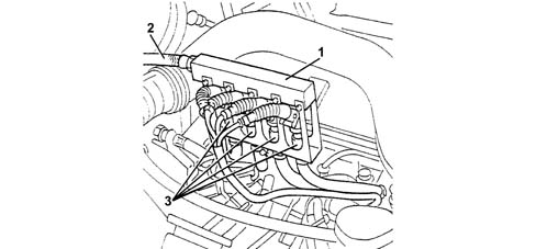
The methane distribution unit is illustrated in the diagram belowThe methane distribution manifold (1) is fastened by means of a special bracket to the tappet cover and to the cylinder head. It receives methane at low pressure from the flexible pipe (2) which acts as a connection with the pressure reduction unit and distributes it to the four injectors (3).
METHANE INJECTORS
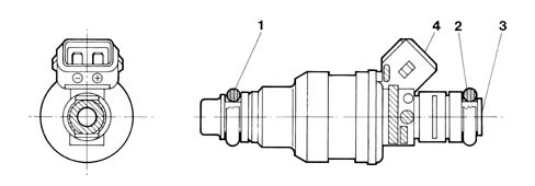
The special methane injectors (shown in the diagram) are the sonic type supplied by Bosch.The main difference between these injectors and those for petrol lies in the fact that they have a larger nozzle for the methane outlet and operate at a considerably higher pressure (9 ± 1 bar). As a result, the quantity of methane injected depends solely on the injector opening time (injection time) which is established by the CNG electronic control unit. Since the pressure downstream of the injector is irrelevant, there is no need to fit a pressure differential regulator like on petrol systems.The injector operating logic is the "phased, sequential" type, in other words the four injectors are operated individually depending on the engine cylinder inlet sequence, whilst the supply for each cylinder can already begin during the expansion stroke until the inlet stroke has already started.The injectors are fastened by two injector holder brackets, one upper one and one lower one which keep them in position; two rubber seals (1) and (2) ensure the seal for the two half brackets.The two injector holders are secured to one another and to the tappet cover and the cylinder head; there are rubber gas pipes from each injector to the methane introduction nozzles located on each inlet duct.The pipes are fastened to the injectors and to the nozzles by bands.The methane supply takes place at the top part (3) of the injector (top feed); the connector for the injector operation engages in the housing (4).Connector Pin OutThe connector pin out is illustrated in the diagram.Checking the resistanceInjector resistance may be measured by disconnecting the connector and connecting an ohmmeter as shown in the figure. The reading should be 4.6 Ohm.
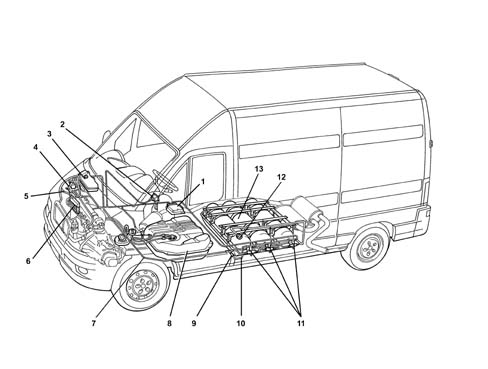
The diagram below illustrates the location of the bipower system components on the vehicle
1 - Injection management control unit11 - Valve assembly on canister complete with cut out solenoid valve, manual cut out valve (tap) and single-acting valve on methane introduction pipe12 - Methane filler complete with single-acting valve2 - Surround for SEDIMO "Petrol or Methane fuel system selection" panel3 - Coolant reservoir4 - Pressure reduction unit5 - Methane low pressure pipe6 - Methane injectors assembly7 - Methane high pressure pipe (canister - reduction unit)8 - Petrol tank and filler9 - Filler valve with rapid connector10 - High pressure methane introduction pipe (filler)13 - Reinforced cradle structure containing methane canisters
LOCATION OF BIPOWER SYSTEM COMPONENTS IN ENGINE COMPARTMENT
The diagram below illustrates the location of the bipower system components on the vehicle
1 - Methane high pressure pipe2 - Pressure reduction unit3 - Methane cut out solenoid valve4 - Methane pressure sensor5 - Engine coolant circulation pipes inside pressure reduction unit6 - Methane low pressure pipe7 - Methane distribution manifold to injectors8 - Methane injectors9 - Intake manifold absolute pressure sensor10 - Throttle position sensor11 - Engine rpm and TDC sensor
Methane pressure sensor
The pressure sensor (1) is fitted on the pressure reduction unit (2) at the high pressure line intake (3).
The diagram below illustrates the location of the sensor on the pressure reduction unit.
The function of the sensor on the methane high pressure line is to:Indicate the amount of methane in the canisters (petrol/methane switching selector LED).provide information for the control unit for the automatic switching from methane operation to petrol operation if the methane pressure is too low (below 15 bar).
Operation
It is a capacitive type sensor (where the sensitive element consists of two gold-plated ceramic discs) which contains the signal air conditioning circuit. It receives a supply voltage of 5V.Wiring connector
The sensor pin out is illustrated in the diagram.
B19 - EarthB12 - Power supplyB4 - output signalThe numbers in the boxes indicate the CNG control unit terminals.The electrical check is carried out by placing a bridge (2) to be constructed in situ (not supplied as spares) between the sensor (1) and the connector (3) in order to supply the sensor and receive the output signal using a multimeter (voltmeter).Close the methane cut out tap (valve unit in luggage compartment).Place the bridge between the sensor and the connector.Detach the sensor and check that the output voltage is 500 mVThe end of scale check involves filling the methane canister and checking that the sensor output voltage is approximately 4.5 Volt (this should be the reading at a pressure of 200 bar which corresponds to the canister being completely full).
Rpm and TDC sensor
The rpm sensor (1) gives a reference for the angular position of the crankshaft (TDC identification). It is secured to the gearbox bell housing and faces the phonic wheel. (see diagram)1 - Rpm and TDC sensor2 - Electrical winding3 - Permanent magnet4 - Twisted cable (40 turns/metre with anti-interference sheath (SC)5 - Flywheel with (60 - 2) 58 teeth on engine flywheel6 - Progress of inductive signal produced7 - Variation in the signal due to the missing 2 teeth or timing referenceThis consists of a sealed tubular case containing a permanent magnet (3) and an electric winding or copper coil (2). It is connected to the electronic control unit via terminals 11 and 28.The cables are twisted (40 turns/metre) and covered by an anti-interference sheath connected to earth. A heat-resistant PVC sheath covers leads and shielding.The flywheel (5) comprises 58 teeth plus one space equivalent to the size of the two missing teeth (7). The reference defined by the space for the two missing teeth constitutes the basis for detecting the point of synchronism (TDC).The synchronism point is recognised at the end of the first tooth (8) following the gap left by the two missing teeth: when this passes beneath the sensor, the crankshaft is located with piston pair 1-4 at 114° before TDC.Operation is as follows: The sensor permanent magnetic field (3) affects the winding (2) and also the phonic wheel (5) teeth. In practice, when the tooth is in front of the sensor, the magnetic flow is maximum. When the gap passes, the flow is minimum. During phonic wheel (5) rotation, whenever a tooth tends to approach the sensor, the signal rises toward the positive voltage value (+). It becomes zero during the tooth-sensor alignment stage and passes through a negative voltage value (-) as the tooth moves away.The graph and the waveform (6) (which corresponds to the mechanical position of the phonic wheel) is an e.m.f. set up in the sensor winding and may range from a few volts at low rpm to several tens of volts at a high rpm. Because the resulting voltage depends on the distance between sensor core and tooth tip, it is extremely important that this height, known as the GAP is between 0.5 +1.5 mm.The train of analogue signals (diagram 6) generated by the sensor (1) is sent to an appropriate converter circuit (A/D analogue digital) in the electronic control unit (ECU) and used for:Calculating the engine rpm;Calculating the optimal ignition advance.Wiring connector
The connector pin out is illustrated in the diagram
The sensor is connected to the CNG control unit (terminals A17 and A18) by means of twisted cables covered in an anti-interference sheath connected to earth.As the sensor is in series to the two control units, the CNG control unit input signal leaves via terminals A7 and A8 (unchanged if the engine is running on petrol, suitably treated, on the other hand, if the engine is running on methane) and reaches terminals 28 and 11, respectively, of the basic control unit.Checking the gapThe sensor is fitted in production with tolerances that ensure a gap of 0.5 - 1.5 mm without the need for further adjustments. (see diagram)1 - Sensor2 - Fitting plane3 - Phonic wheel toothThis gap is also guaranteed if a replacement sensor is fitted. However, if a check needs to be carried out, proceed as follows:1. measure the distance between the end of the sensor and the lower part of the sensor bracket (distance "a")2. measure the distance between the fitting plane on the gearbox and the upper part of the tooth (distance "b").The gap (t = b-a) should be between 0.5 and 1.5 mm.Checking the resistanceSensor resistance may be measured by disconnecting the connector and connecting an ohmmeter at the sensor terminals.
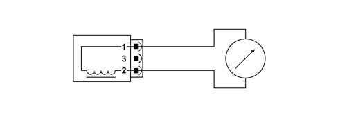
The resistance control circuit is illustrated in the diagram (Resistance: 1134 - 1386 Ohm at 20 °C.)
Methane canister valve unit
The valve unit is fitted directly on the canister and has been designed to carry out the following functions safely:methane canister filling,engine fuel supply.The diagram below shows the valve assembly.Canister fillingDuring the filling stage the pressurized methane (200 bar) reaches the inlet (8) and overcomes the single-acting valve (3). With the engine switched off the solenoid valve (1) is de-enerized:the outlet towards the engine is closed whilst the passage from the filler to the canister is open allowing the filling of the actual canister.Engine fuel supplyWith the engine running on methane (ignition in ON position and petrol-methane switching button pressed) the solenoid valve (1) is energized: the passage from the canister to the pressure reduction unit is open, allowing the fuel supply to the engine.
Solenoid valve operation
The solenoid valve (1) directly on the valve assembly has the main function of managing the flow of methane coming out of the actual canister, intercepting the outlet duct from the valve assemblyThe inlet duct, on the other hand, is fitted with a single-acting valve (3) which prevents the flow of methane from the canister to the filler (for improved safety, a second single-acting valve is fitted on the filler itself).The solenoid valve is electrically supplied by the ignition via a special relay and is earthed through the inertia switch.With the solenoid valve de-energized (engine switched off) the route towards the pressure reduction unit is closed and methane operation is possible.With the solenoid valve energized (ignition key in ON position and petrol/methane switch released), the route to the pressure reduction unit is open placing the canister in contact with the engine fuel supply system.The flow of methane towards the outside is prevented by the single-acting valve (3).
Manual cut out valve (tap)
The valve unit is equipped with a manual methane cut out tap (2) located upstream of the solenoid valve (1). Opening/closing it either allows or prevents the escape or intake of methane from the canister and it is important if any servicing operations are being carried out on the system.
Single-acting valve
The single-acting valve (3) is fitted in the valve assembly methane inlet duct and is designed to prevent the flow of methane from the solenoid valve to the filler (for improved safety, a second single-acting valve is fitted on the actual filler).
Safety devices
In order to prevent excess pressure or the rapid draining of the canister, the valve unit is equipped with the following safety devices:meltable pad (4).flow restricter (5).Meltable padIf, as a result of outside forces, the temperature increases above 110 ± 10 C (for example, because of a fire), the pad melts, allowing the methane in the canister to escape via a calibrated port thereby completely eliminating the danger of excess pressure. The methane that has escaped is then directed outside the luggage compartment by means of a corrugated protection pipe.Flow restricterIf a pipe breaks or there is an escape of methane from the valve unit (for example, in the case of an impact), the flow restricter (5) intervenes by limiting the flow of methane to around 0.5% of the setting for normal engine operation, thereby preventing the danger arising from a large fuel flow rate. The flow restricter is located on the threaded shank of the valve unit so that it remains inside the canister to guarantee operation even if the solenoid valve breaks as the result of an impact.
High pressure methane pipe
The copper pipes are covered in a plastic material (by law) and have an outside diameter of around 8 mm.The pipe runs along the left side of the floor panel to the side of the petrol tank.
Methane pressure reduction unit
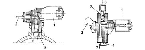
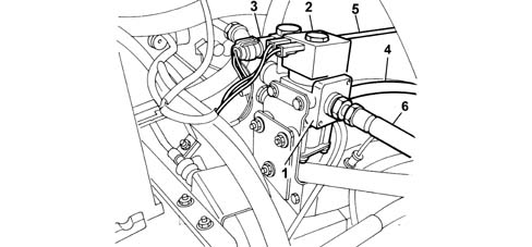
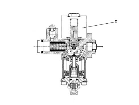
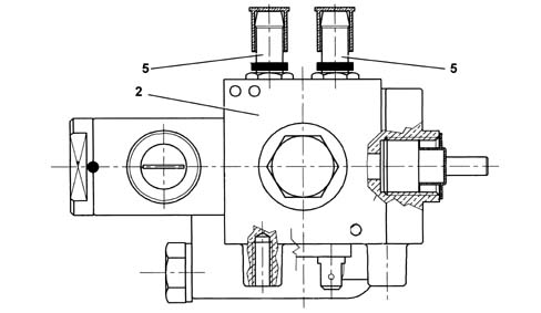
The diagram below shows the pressure reduction unit
The pressure reduction unit is fitted in the engine compartment. It includes the actual pressure reduction unit (1) and a cut out solenoid valve (2); a methane pressure sensor (3) is also fitted on it.The high pressure pipe (5) conveys the methane from the canister to the pressure reduction unit inlet, whilst the low pressure pipe (6) is connected at the unit outlet.
Pressure reduction unit operation
The pressure reduction unit has the task of reducing the pressure of the methane from the value in the canister to the supply valve for the methane injectors (9 ± 1 bar), in all engine operating conditions.The pressure reduction takes place in one stage where the pressure is decreased from 200 to 9 bar.When the pressure in the canister decreases to approximately 15 bar, the CNG control unit automatically switches from methane to petrol operation because at a pressure of below 15 bar at the reduction unit inlet this would automatically result in a pressure of below 9 bar at the oulet and this pressure would be too low for the engine to run smoothly.Since the temperature of the methane decreases considerably as a result of its expansion due to the sudden increase in pressure, the engine cooling circuit has a branch (7) that allows the engine coolant to heat the pressure reduction unit in order to prevent any problems due to the rise in temperature. (The diagram shows the assembly seen from above).
Cut out solenoid valve
The methane cut out solenoid valve is the normally closed type. This means that it only allows the flow of methane when it is energized. It is electrically supplied by the ignition key by means of a special relay and is earthed directly.When the solenoid valve is not supplied, the flow of methane from the canister to the engine is prevented.With the solenoid valve supplied (ignition key in ON position and petrol/methane switch released) the methane passage between the two stages of the pressure reduction unit is open and consequently there is a flow to the injectors.Methane pressure sensorThere is a pressure sensor/transducer (3) fitted on the reduction unit casing, connected to the upstream high pressure pipe (6), that sends a signal to both the methane canister level gauge in the instrument panel and to the CNG control unit which uses it for the operating logics (see electrical/electronic circuit).
Methane distribution manifold
The methane distribution unit is illustrated in the diagram below
The methane distribution manifold (1) is fastened by means of a special bracket to the tappet cover and to the cylinder head. It receives methane at low pressure from the flexible pipe (2) which acts as a connection with the pressure reduction unit and distributes it to the four injectors (3).
Methane injectors
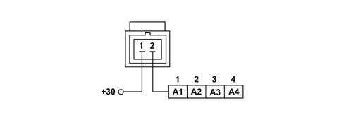
The special methane injectors (shown in the diagram) are the sonic type supplied by BoschThe main difference between these injectors and those for petrol lies in the fact that they have a larger nozzle for the methane outlet and operate at a considerably higher pressure (9 ± 1 bar). As a result, the quantity of methane injected depends solely on the injector opening time (injection time) which is established by the CNG electronic control unit. Since the pressure downstream of the injector is irrelevant, there is no need to fit a pressure differential regulator like on petrol systems.The injector operating logic is the "phased, sequential" type, in other words the four injectors are operated individually depending on the engine cylinder inlet sequence, whilst the supply for each cylinder can already begin during the expansion stroke until the inlet stroke has already started.The injectors are fastened by two injector holder brackets, one upper one and one lower one which keep them in position; two rubber seals (1) and (2) ensure the seal for the two half brackets.The two injector holders are secured to one another and to the tappet cover and the cylinder head; there are rubber gas pipes from each injector to the methane introduction nozzles located on each inlet ductThe pipes are fastened to the injectors and to the nozzles by bands.The methane supply takes place at the top part (3) of the injector (top feed); the connector for the injector operation engages in the housing (4).Connector Pin Out
The connector pin out is illustrated in the diagram.
Checking the resistanceInjector resistance may be measured by disconnecting the connector and connecting an ohmmeter as shown in the figure. The reading should be 4.6 Ohm.
BIPOWER SYSTEM CONSTRUCTION SPECIFICATIONS
The system for running on two types of fuel comprises the Magneti Marelli IAW 48P2 system for petrol operation and the Metatron METAFUEL 5D0 system for operating on CNG. The two systems are connected via a high speed CAN line.The Magneti Marelli IAW 48P2 system belongs the category of systems integrated with:inductive discharge, digital, electronic ignitionstatic advancesequential, phased type electronic injection (1-3-4-2).The Metatron METAFUEL 5D0 belongs the category of systems integrated with:sequential, phased type electronic injection (1-3-4-2).The CNG system is clear for the basic system for all components and the operation of the basic system is not affected in all operating conditions.The two control units share some of the system elements. This sharing is transparent to the basic system.The list of components shared by the two systems, connected in parallel, is as follows:intake manifold pressure sensor;throttle position sensor;engine rpm sensor;engine timing sensor;Lambda sensor upstream of the catalytic converter.The list of additional components for the methane system is as follows:electronic injection unit for METAFUEL 5D0CNG pressure sensor on the pressure reduction unit casing; CNG cut out solenoid valve relay on the canisters;CNG cut out solenoid valves on the canisters;solenoid valve and pressure reduction unit;CNG / petrol switch (SEDIMO);CNG injector relay;injectors;petrol pump cut out relay;1 - Methane engine management control unit2 - Injection system relay3 - Battery4 - Ignition switch5A - CNG residual pressure gauge (SEDIMO)5B - Two LEDs - "petrol mode" (orange) and "gas mode" (green) (SEDIMO)5C - Petrol or methane operating mode selector (SEDIMO)6 - Diagnostic tester connection7 - Methane solenoid valve relay (on canisters and on pressure reduction unit)8 - Solenoid valves on canisters9 - Methane canisters10 - Inertia switch11 - Petrol pump12 - Petrol pump cut out relay13 - Lambda sensor upstream of the catalyzer14 - Solenoid valve on pressure reduction unit15 - Methane pressure sensor16 - cut out solenoid valve on methane pressure reduction unit17 - Air pressure and temperature sensor18 - Engine timing sensor19 - RPM and TDC sensor20 - Methane manifold and injectors21 - Injector relay22 - Petrol engine management control unit23 - Throttle valve position sensor
OPERATION
The system is configured to normally run on methane. The two control units are always supplied whilst the engine is running.Methane/petrol switching can take place:by means of a manual control on the mode selector (SEDIMO) located in the dashboard.automatically when ordered by the methane engine management control unit if the methane in the tank has run out (pressure in the canister less than 11 bar) or in the recovery condition when methane operation is not advisable.The operating mode is signalled by means of the PETROL operation warning light (POWER MODE) in the sedimo component. Irrespective of the switch position, this indicator shows the operating mode - methane (green) or petrol (orange) by means of the two LEDs.
Diagram showing information entering/leaving the control unit
Communication between the petrol engine management control unit and the CNG engine management control unit takes place via the CAN line1 - Methane engine management control unit2 - Methane canisters3 - CNG pump and CNG solenoid valve relay (on the tank and on the pressure regulator)4 - CNG cut out solenoid valves5 - CNG pressure sensor on pressure regulator6 - Lambda sensor upstream of the catalytic converter7 - Diagnostic tester connection8 - Petrol or CNG operating mode selector with built-in operating mode indicator and pressure gauge9 - CNG injectors10 - CNG injector relay11 - Battery12 - Ignition switch13 - Petrol pump cut out relay14 - Petrol pump15 - Throttle valve position sensor16 - Air pressure sensor17 - Petrol engine management control unit18 - Rpm and TDC sensor19 - Engine timing sensor
OPERATING LOGICS
Petrol operation
In this operating mode there are no functional variations in relation to the basic system.The Magneti Marelli 48P2 basic electronic unit does not alter its behaviour and the system management strategies are the same as for the basic version.The specific elements for the CNG system do not interfere in any way with the basic system.
Methane operation
The engine runs on CNG after starting which always takes place using petrol (obviously with the selector positioned to CNG mode before starting). The petrol pump is deactivated during CNG operation, except during starting, for a period of a few seconds, corresponding to the activation of the CNG injection, necessary in order to be able to carry out the fault diagnosis of the deactivation relay.The METAFUEL 5D0 electronic unit manages the sequential, phased type injection of the CNG, the activation of the CNG cut out solenoid valves and the deactivation of the petrol pump. All the other engine management functions, including the ignition advance, are left to the basic unit. Injection takes place directly through the operation of the specific CNG system injectors. The ignition advance is adjusted by sending the basic electronic unit the advance variation to be added to the one for petrol operation. This communication takes place via the CAN line between the two control units. The other basic electronic unit functions are carried out normally and all the input signals remain unchanged. All the commands are implemented as usual (stepper, ignition, etc.).The METAFUEL 5D0 electronic unit processes the information coming from the basic system sensors, that coming via the CAN line from the 48P2 control unit and the information coming from the additional sensors for CNG operation in order to recognize the system operating conditions and produce suitable commands for the CNG injectors.The activation of the CNG cut out solenoid valves and the deactivation of the petrol pump takes place when switching from petrol to methane. When switching from methane to petrol, the METAFUEL 5D0 electronic unit operates in the opposite way to previously (i.e. it deactivates the CNG cut out solenoid valves and reactivates the petrol pump). In this case the petrol pump is switched on immediately to pressurize the system.The management strategies use typical curves and control parameters stored in the METAFUEL 5D0 electronic unit memory. The calibration figures are defined on the basis of performance, consumption, emission and driveability aims.The specific management strategies for the CNG system are basically as follows:Engine Signal ManagementIgnition managementInjection managementIdle speed managementStart-upOperation during acceleration and decelerationCut-off operationOperation in full load conditionsProtection beyond revsBarometric correctionFuel vapour recoveryControl of combustion gases - Pre-catalyzer Lambda sensorAir conditioning compressor connectionResidual fuel pressure signalPetrol pump operationMethane solenoid valve operation;Methane injector operation;Switching between two operating modes (petrol and methane)Connection with electronic key (Fiat CODE)System self-diagnosis
Engine Signal Management
The METAFUEL 5D0 electronic unit recognizes the engine timing and determines the injection timing angle. This recognition takes place by processing the signals coming from the timing sensor and from the rpm and TDC sensor. These two signals make up the engine signals.
Ignition management
The coil charging time and the moment of ignition in relation to TDC are always determined and managed by the basic electronic unit which receives the variation in the advance to be implemented from the METAFUL 5D0 via the CAN.The METAFUEL 5D0 electronic unit memory contains a map of the advance shift values according to the engine speed and load conditions. The calculation of the advance correction involves selecting a basic value and correcting in according to the coolant temperature.
Injection management
The aim of the fuel management is to supply the correct amount of fuel required by each cylinder to satisfy the objectives of performance, consumption and engine emissions. The METAFUEL 5D0 unit does not manage the starting stage.The injection is the sequential, phased type.The METAFUEL 5D0 control unit uses an indirect type engine load measurement system (speed-density). This method is used to calculate the quantity of fuel to inject into each cylinder for each engine cycle.The methane is supplied by modulating the injector opening time. The injector inlet pressure is established by the pressure reduction unit.The METAFUEL 5D0 unit injection strategies make it possible to supply the correct amount of CNG to the engine in all operating conditions (acceleration, deceleration, altitude, cold weather).
Idle speed management
The idle speed management (stepper management) is carried out by the basic electronic unit; the METAFUEL 5D0 unit modifies the idle speed by means of a suitable offset transmitted via the CAN.
Start-up
The engine is always started up on petrol.
Operation during acceleration and deceleration
These operating conditions are identified by means of the throttle position and manifold pressure signals.During these two stages the METAFUEL 5D0 unit adjusts the fuel injection as quickly as possible in order to maximize acceleration torque and ensure optimum driveability during deceleration.
CUT-OFF operation
The fuel cut off strategy is implemented when the throttle is closed at high engine speeds. This strategy is only enabled above a certain coolant temperature level. The METAFUEL 5D0 electronic unit manages the inlet and outlet from this stage in order to reduce emissions during these engine operating conditions.
Operation in full load conditions
Full load opeartion is managed by the METAFUEL 5D0 electronic unit with air/CNG mixture enrichment strategies that are similar to those for petrol engine management systems.
Protection beyond revs
The METAFUEL 5D0 electronic unit manages the protection of the engine outside of revs. This protection involves cutting off the injection when a given speed is exceeded. Normal injection is resumed when the speed returns to below the critical value.
Barometric correction
There is a strategy in the METAFUEL 5D0 control unit that recognizes the altitude and implements a barometric correction of the mixture strength.
Control of combustion gases - pre-catalyzer Lambda sensor
The METAFUEL 5D0 electronic unit uses the signal for the Lambda sensor upstream of the catalyzer to control the metering of the air/CNG mixture in order to ensure maximum catalyzer conversion efficiency.The METAFUEL 5D0 electronic unit manages the heaters for the two Lambda sensors, via the CAN, located upstream and downstream of the catalyzer.
Air conditioning compressor connection
The METAFUEL 5D0 electronic unit is not connected to the air conditioning system.The switching on and off of the compressor in certain operating conditions to improve the performance of the engine is managed by the basic electronic unit through the same modes and operating conditions as for the basic system.
Residual fuel pressure signal
The METAFUEL 5D0 electronic unit receives the canister residual pressure signal from the CNG pressure sensor fitted on the pressure reduction unit. This information is then sent by the METAFUEL 5D0 control unit to the special indicator on the left of the instrument panel.
Petrol pump operation
The petrol pump is closed to earth by the inertia switch and is operated by the METAFUEL 5D0 electronic unit via a special relay.The petrol pump is stopped:if there is a petrol/methane switch;if the inertia switch has gone off.When switching from CNG to petrol the METAFUEL 5D0 electronic unit immediately reactivates the petrol pump to pressurize the system.
Methane cut out solenoid valve operation
There are 4 CNG cut out solenoid valves:1 solenoid valve fitted on each canister (3 in number);1 solenoid valve fitted on the pressure reduction unit.The 2 solenoid valves are connected to one another in parallel, closed to earth by the inertia switch and operated by the METAFUEL 5D0 electronic unit by means of a special relay. The solenoid valves are closed:if the engine speed goes below a certain level;after a certain time with the key ON without the engine being started up (timed enablement);if there is a CNG/petrol switch;if the inertia switch has gone off.After the CNG/petrol switch, the METAFUEL 5D0 electronic unit deactivates the CNG cut out solenoid valves.
Methane injector operation
The operation of the CNG injectors is the phased sequential type.The injector timing varies according to the engine speed and the intake air pressure in order to improve the cylinder filling with benefits in terms of consumption, driveability and pollution.The injectors receive an electrical supply via a specific relay: the CNG engine management control unit closes the contacts for the appropriate part of the CNG injectors according to the situation
Switching between two operating modes (petrol and methane)
This function is regulated by the METAFUEL 5D0 electronic unit and by a switch built into the component (SEDIMO).Position "G" of the selector (1) indicates the choice to run on gas (green LED on) (2), whilst running on petrol is indicated by the amber yellow LED lit up (3). There is also a residual pressure gauge (4) consisting of a series of green LEDs + 1 yellow LED for the reserve condition. This indicator is activated when the last LED is on and the reserve condition exists.1 - Operating mode switch2 - Green LED (methane operation)3 - Amber/yellow LED (petrol operation)4 - Residual pressure gaugeThe lighting up logic for the "petrol mode" indicator in the SEDIMO component is, irrespective of the selector switch position, to signal:a) CNG operation = green LED on b) petrol operation = amber yellow LED onThe switching between the two operating modes, when instructed by the user, can take place at any time, but only when the engine speed is below a certain level.The pressure of the CNG in the canisters is utilized in identifying the "empty canisters" condition for the automatic return to petrol operation. As a result of the canisters being drained, the pressure in the rail decreases rapidly to below a certain level.Switching from petrol to methaneThe following cases are possible:1. Manually, by the user with the engine switched offSelector switch position: methane gas"Petrol mode" LED lit up:During starting the "petrol mode" LED is on (activated), thereby indicating that the engine is supplied with petrol. When the engine has been started up (as soon as cranking is over) the switch to methane takes place and the "methane mode" warning light lights upSwitching to CNG is prevented if the pressure of the methane is below a level corresponding to the "empty canister" situation, if the engine coolant temperature is too low or if a fault has been located in the system.2. Manually, by the user with the engine running.Selector switch initial position: petrol"Petrol mode" LED initial coming on:By selecting the methane mode the user starts the petrol to CNG switching function which only takes place when the following conditions are satisfied:CNG canister pressure above a certain level;engine coolant temperature above a certain level;no faults detected during the fault diagnosis of the METAFUEL 5D0 electronic unit.The switching does not take place unless all the conditions are satisfied. When the switching has taken place the "methane mode" LED in the SEDIMO device is lit up.Switching from methane to petrolThe following cases are possible:1. Automatically (with the engine running).Initial selector position: "methane mode"."Methane mode" LED initial coming onThe automatic switching from methane to petrol takes place according to decisions by the METAFUEL 5D0 unit control strategies and only if the following operating conditions are satisfied:methane pressure below a certain level;identification of a fault in the systemIf one of the conditions has been satisfied, the switching from CNG to petrol takes place immediately and the "petrol mode" LED in the SEDIMO device lights up. The position of the selector remains unchangedAfter the switching has taken place, CNG operation is completely inhibited until the cause of the automatic switching is eliminated (fuel supply or elimination of the fault).2. Manually, by the user with the engine running.This operation is only permitted if the engine speed is below a certain level"Methane mode" selector initial position"Petrol mode" LED initial coming on.When switching to the petrol mode the user starts the switching function from CNG to petrol which takes place immediately together with the "petrol mode" indicator in the SEDIMO component coming on
Connection with electronic key
The METAFUEL 5D0 control unit is not connected to the electronic key control unit (Fiat CODE).The electronic key system only maintains its operation with the basic system; therefore, in order to be able to switch to methane, it is necessary to receive the go ahead from the petrol control unit and this go ahead is given if the check with the Fiat CODE is okay and the operation with the electronic key is guaranteed in all conditions.Starting with a key that has not been memorized in the electronic key control unit is not permitted in either operating mode (petrol or CNG). The procedure for personalizing the vehicle or programming the keys is the same and should be carried out in the petrol mode.
System self-diagnosis
The METAFUEL 5D0 electronic unit carries out the fault diagnosis of the input/output, cyclically checking the signals and an internal self-diagnosis programmes the codes in the EEPROM in the case of malfunctions (passive self-diagnosis).It is also possible to activate the individual actuators, using the diagnostic equipment, checking their efficiency (active self-diagnosis).The total cancellation of the EEPROM is carried out by means of the diagnostic equipment.If there is a fault, the control unit manages the alternative functions to keep the engine running where possible to allow the vehicle to reach a service centre or, in more serious cases, it automatically switches the system to petrol operation, switching off the residual pressure indicator in the SEDIMO device (recovery).
PASSIVE SELF-DIAGNOSIS
The METAFUEL 5D0 electronic unit carries out the fault diagnosis of the input/output, cyclically checking the signals and in the case of malfunctions, programming the codes in the EEPROM (passive self-diagnosis). The fault diagnosis carried out and the recovery actions in the case of a fault in the following components are reported:
Manifold pressure sensor
The METAFUEL 5D0 electronic unit carries out the following electrical fault diagnosis on the signal coming from the manifold pressure sensor every 4 ms:short circuit to earth;short circuit to Vbattery or open circuit.If a fault is detected, the control unit implements the following recovery actions:return to petrol operating mode and switching on "petrol mode" indicator in the mode selector;warning light in instrument panel lit up.
Throttle position sensor
The METAFUEL 5D0 electronic unit carries out the following electrical fault diagnosis on the signal coming from the throttle position sensor every 4 ms:short circuit to earth;short circuit to Vbattery or open circuit.If a fault is detected, the control unit implements the following recovery actions:return to petrol operating mode and switching on "petrol mode" indicator in the mode selector;warning light in instrument panel lit up.
Methane pressure sensor
The METAFUEL 5D0 electronic unit carries out the following electrical fault diagnosis on the signal coming from the CNG pressure sensor cyclically:Short circuit to earth;Short circuit to Vbattery or open circuit.If a fault is detected, the control unit implements the following recovery actions, but only if there is a short circuit to earth:Return to petrol operating mode and switching on "petrol mode" indicator in the instrument panel;Switching on of the selector warning light;The pressure indicator in the SEDIMO is off.
CAN line
The METAFUEL 5D0 electronic unit cyclically carries out a functional diagnosis on the CAN line to check for a break in the connection.If a fault is detected, the control unit implements the following recovery actions:return to petrol operating mode and switching on "petrol mode" indicator in the instrument panel foar each individual break; Return to CNG operating mode when the connection is restored, switching off the "petrol mode" indicator in the instrument panel;definitve return to petrol operating mode and then switching on of the "petrol mode" indicator in the instrument panel after 5 interruptions in a single trip and switching on of the warning light in the instrument panel.
Pre-catalyzer Lambda sensor
The METAFUEL 5D0 electronic unit cyclically carries out a functional fault diagnosis signalling that the Lambda sensor is not working properly in the case of a fault or malfunction.If a fault is detected, the control unit implements the following recovery actions:disabling closed-loop mixture strength check;inhibition of self-adjustment strategies.
Rpm sensor
The METAFUEL 5D0 electronic unit checks the accuracy of the counting of the impulses coming from the rpm sensor facing the flywheel with 58 teeth, signalling if there is a fault or malfunction:signal not present.If a fault is detected, the control unit implements the following recovery actions:resynchronization;the vehicle does not move or cuts out.
Timing sensor
The METAFUEL 5D0 electronic unit cyclically carries out a fault diagnosis on the timing sensor signalling the following in the case of a fault or malfunction:signal not plausible.There are no recovery actions planned, the system will operate at 360 degrees with the correct or incorrect timing.
Methane injectors
The METAFUEL 5D0 electronic unit cyclically carries out an electrical fault diganosis on the CNG injectors signalling the following problems:injector cold side open circuit;injector cold side short circuit to earth;injector cold side short circuit to Vbattery.If a fault is detected, the control unit implements the following recovery actions:return to petrol operating mode;warning light in instrument panel lit up.
Methane injector relay
The METAFUEL 5D0 electronic unit cyclically carries out an electrical fault diganosis on the CNG injector relay coil every 131 ms, signalling the following problems:short circuit to earth or open circuit: this fault diagnosis is only possible in the petrol operating mode;short circuit to Vbattery: this fault diagnosis is only possible in the CNG operating mode.If a fault is detected, the control unit implements the following recovery actions:return to petrol operating mode;warning light in instrument panel lit up.
CNG cut out solenoid valve relay
The METAFUEL 5D0 electronic unit cyclically carries out an electrical fault diganosis on the CNG cut out solenoid valve relay coil every 131 ms, signalling the following problems:short circuit to earth or open circuit: this fault diagnosis is only possible in the petrol operating mode;short circuit to Vbattery: this fault diagnosis is only possible in the methane operating mode.If a fault is detected, the control unit implements the following recovery actions:return to petrol operating mode;warning light in instrument panel lit up.
Petrol pump cut out relay
The METAFUEL 5D0 electronic unit cyclically carries out an electrical fault diganosis on the petrol pump cut out solenoid valve relay coil every 131 ms, signalling the following problems:short circuit to earth or open circuit: this fault diagnosis is carried out, in CNG operating mode, once only during starting on petrol and then switching to CNG;short circuit to Vbattery: this fault diagnosis is possible in both CNG and petrol operating mode.There are no recovery actions.
METAFUEL 5D0 INJECTION CONTROL UNIT
The control unit is fitted under the passenger seat and is capable of withstanding high temperatures.It is a digital type unit with a microprocessor featuring a high calculation capacity and is accurate, reliable, versatile, with low energy consumption and is maintenance-free.The task of the electronic control unit is to process the signals coming from the additional sensors belonging to the CNG system, the signals for the sensors shared with the petrol system and the information coming from the Magneti Marelli 48P2 control unit through the application of software algorithms and to control the operation of the actutators (in particular the CNG injectors and CNG cut out solenoid valves) in order to ensure the optimum operation of the engine.
Metaful 5D0 control unit PIN OUT
The diagram below shows the control unit pin out.
1 - Direct supply from the battery2 - Not connected3 - Diagnostic socket (line K - TX)4 - Not connected5 - Not connected6 - Not connected7 - Not connected8 - Not connected9 - Not connected10 - GAS mode signal11 - Timing sensor (negative)12 - Timing sensor (positive)13 - Not connected14 - Not connected15 - Diagnostic socket (line L - RX)16 - Outside sensor supply17 - Not connected18 - Not connected19 - Not connected20 - Not connected21 - Not connected22 - Digital earth23 - CAN-L line24 - Not connected25 - Not connected26 - Not connected27 - Battery earth direct return28 - Radiofrequency earth29 - Not connected30 - GAS pressure sensor signal31 - Not connected32 - Throttle position sensor (negative)33 - Absolute pressure sensor (negative)34 - Supply controlled by ignition (+15)35 - Pre-catyalyzer Lambda sensor signal (negative)36 - Not connected37 - Not connected38 - CAN-H line39 - Not connected40 - Not connected41 - Not connected42 - Not connected43 - Throttle position sensor signal (positive)44 - Absolute pressure sensor signal45 - Not connected46 - Pre-catyalyzer Lambda sensor signal47 - Petrol or methane GAS operation selector input48 - Not connected49 - Not connected50 - Not connected51 - VRS rpm sensor (positive)52 - VRS rpm sensor (negative)53 - Not connected54 - GAS cut out solenoid valves relay feed55 - Battery earth56 - Cylinder no. 4 injector.57 - Cylinder no. 2 injector.58 - Not connected59 - CNG injector supply return (INJ+)60 - CNG level analogue signal output61 - Battery earth62 - Battery earth63 - Cylinder no. 3 injector.64 - Cylinder no. 1 injector.65 - Not connected66 - CNG injector supply return67 - Not connected68 - GAS injector relay feed69 - Not connected70 - Not connected71 - Not connected72 - Not connected73 - Not connected74 - Petrol pump deactivating relay feed75 - Not connected76 - Battery earth77 - Not connected78 - Not connected79 - Not connected80 - CNG injector supply return (INJ+)