Descriptions
ANTI-LOCK BRAKES (ABS BOSCH 5.3)
Engines: 2.0 16V, 2.0 JTD 8V, 2.3 JTD 16V, 2.8 JTD 8V
COMPOSITION
The Bosch 5.3 ABS is extremely compact (easy to fit), light and reliable.The use of new microhybrid type electronic components, the improvement of the magnetic flows achieved through the new design compact shape of the valve bodies and the reduction in the number of components as a result of pressing the jets directly in the valve seat has allowed the improvements in the solenoid valve modulating specifications.In addition to the anti-lock function, the system controls the distribution of the brake force between the front and rear axles via the EBD function (Electronic Brake-force Distribution) allowing the traditional load proportioning valve on hydraulic braking systems to be dispensed with. In addition to the ABS and EBD systems, some versions may be equipped with an ASR function (ANTI-SLIP REGULATOR).The main system components are:- electronic control unit;
- an electro-hydraulic control unit that modulates the braking pressure at the brake calipers by means of eight solenoid valves, two for each wheel;
- four sensors (5) and (8), one for each wheel, that detect the rotation speed of the actual wheels.
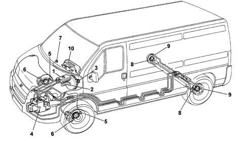
1 - Brake fluid reservoir;
2 - Master cylinder for front and rear wheel brake circuit;
3 - Vacuum brake servo;
4 - Electro-hydraulic control unit with electronic control unit incorporated;
5 - Front wheel rpm sensor;
6 - Front disc brakes;
7 - Failure warning light;
8 - Rear wheel rpm sensor;
9 - Rear drum brakes;
10 - Control panel (braking system failure warning light).
- the hydraulic system pipes;
- specific electrical wiring;
- a switch on the brake pedal for detecting the braking conditions;
- a warning light (7) in the control panel.
COMPONENTS
Electro-hydraulic unit
The electro-hydraulic unit consists of two sections fastened to one another: an electronic type control unit and an electro-hydraulic type one.The electronic control unit is connected to the ABS wiring by means of a multiple connector with 31 terminals.According to the signals coming from the sensors and, with the assistance of programmes stored in its memories, the electronic control unit controls the electro-hydraulic control unit.The electro-hydraulic control unit is connected to the brake pump and to the ABS components by means of the braking system pipes.Electronic control unit
The electronic control unit consists of hybrid circuits with resistances, diodes, transistors and integrated logic circuits. The core of the system consists of two CMOS microprocessors with 16 K of ROM which run the same programme independently with feed back. Both receive the same input signals that they each process individually and only when the results obtained are identical does the electronic control unit give the operational command to the electro-hydraulic control unit.If this is not the case, for example, if there is a problem in the anti-lock braking system, the device switches itself off and braking takes place conventionally; the failure warning light in the control panel comes on at the same time.The information relating to the fault is stored in a non volatile memory; in effect, one of the two microprocessors has a CMOS EEPROM whose contents are preserved even if the battery voltage fails. The task of the this memory is to preserve the fault codes so that they can be read in a service situation using the diagnostic equipment.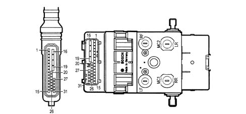
- 1 after inserting the ignition key and for around 4 seconds, it checks the operation of the control unit, the relays that operate the solenoid valves and the connection of the sensors;
- 2 after the engine has been started, as soon as 6 km/h is exceeded, it operates the solenoid valves and the recovery pump for an operational check; it also checks for the presence of the 4 speed signals;
- 3 each time 24 km/h is exceeded, starting with the vehicle stationary, it checks for the presence of the 4 speed signals;
- 4 whilst driving it constantly compares the peripheral speed of the wheels with the reference speed calculated, checks the memory conditions and oversees the operation of the two relays;
- 5 whilst driving it constantly checks the battery voltage.
Electro-hydraulic control unit
The electro-hydraulic control unit is connected to the brake pump and to the brake caliper cylinders by means of the braking system pipes and together with the electronic control unitmakes up the electro-hydraulic unit.Its task is to vary the pressure of the brake fluid in the brake caliper cylinders corresponding to the control signals cming from the electronic control unit.It consists of eight two-way solenoid valves (two for each hydraulic circuit) and a dual circuit recovery pump (2).The eight solenoid valves and the recovery pump are operated by the electronic control unit according to the signals for the four rpm sensors. In particular, the pump allows the recovery of the brake fluid during the pressure reduction stage making it available again upstream of the solenoid valves for the subsequent pressure increase stage.The accumulators make it possible to absorb brake fluid during the pressure reduction stage.The unit is connected to the braking system by means of connectors that can be identified by the codes illustrated.The electro-hydraulic control unit cannot be overhauled and should not be tampered with.It is supplied as spares filled with (DOT 3) brake fluid and with the solenoid valves not supplied.The operation of bleeding and refilling the braking system is the same as that for a traditional system.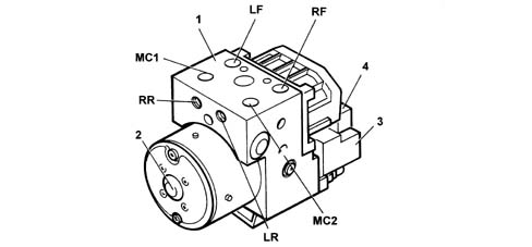
MC1 - Supply connector from brake pump M10x1;
MC2 - Supply connector from brake pump M10x1;
LF - Supply connector to left front brake caliper M10x1;
LR - Supply connector to left rear brake caliper M10x1;
RF - Supply connector to right front brake caliper M12x1;
RR - Supply connector to right rear brake caliper M12x1;
1 - Electro-hydraulic control unit;
2 - Recovery pump;
3 - Electronic control unit;
4 - 31 terminal connector
Wheel rpm sensors
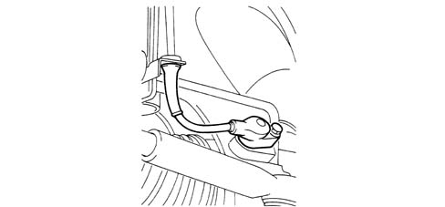
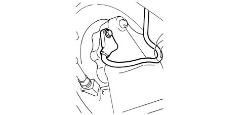
The rpm sensors provide the electronic control unit with all the information needed to operate the electro-hydraulic unit.They measure the driving speed, acceleration, deceleration and wheel slipping.The sensors are the inductive type and are fitted in special housings located in the front and rear wheel dampers.The magnetic flow lines close through the teeth of a flywheel facing the sensor rotated by the wheel. The passage from full to empty depending on whether or not a tooth is present causes a variation in the magnetic flow that is sufficient to produce an electro-motive force at the sensor terminals and consequently an alternating electrical signal at the electronic control unit.The internal sensor elements (coil and permanent magnet) are completely submerged in a protective resin and surrouneded by a plastic casing. A brass fitted on the sensor casing is designed to fasten the latter without distortions.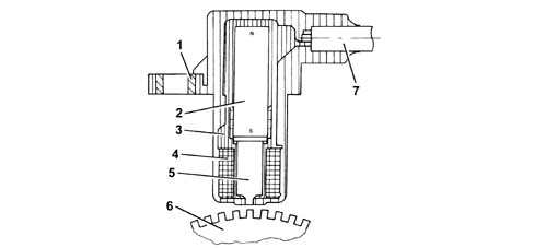
1 - Brass bush;
2 - Permanent magnet;
3 - Plastic sensor casing;
4 - Winding or coil;
5 - Core;
6 - Ring gear or flywheel;
7 - Coaxial paired cable or electrical connection.
- 0.64 - 1.30 mm for the front wheels;
- 0.25 - 1.15 mm for the rear wheels;
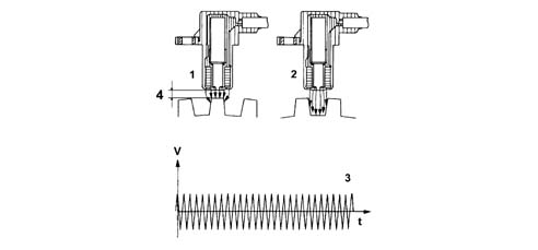
1 - Maximum magnetic flux;
2 - Minimum magnetic flux;
3 - Induced alternating voltage;
4 - Gap.
ABS failure warning light
ABS failure warning light
1 - ABS control unit;
2 - ABS warning light;
D1 - protective diode;
D2 - LED;
R1 and R2 - pressurizing resistances
EBD function failure warning
The EBD function failure is signalled by the ABS warning light coming on at the same time as the braking system failure warning light in the instrument panel lighting up.The warning light in the instrument panel coming on without the ABS warning light (2) coming on does not indicate an EBD malfunction, but one of the other problems signalled (low brake fluid level, brake pad wear, handbrake applied).If there is an EBD function failure, the distribution of the brake force between the front and rear axles starts to fail with a consequent risk of the rear wheels locking during braking in certain conditions.DESCRIPTION OF THE OPERATION OF THE ANTI-LOCK BRAKING SYSTEM
Rest position
Each branch of the Bosch 5.3 ABS hydraulic circuit is equipped with two two-way solenoid valves; all the solenoid valves are managed by the control unit (1).When the pressurizing solenoid valve (9) is deactivated (not earthed by the control unit) it is in an open position, thereby allowing the flow of fluid to the brake caliper.The pressure maintenance is achieved by closing this valve, i.e. providing it with an electrical supply.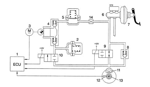
1 - Electronic control unit;
2 - Low pressure accumulator (reservoir);
3 - Recovery pump motor;
4 - Recovery pump;
5 - High pressure accumulator (damping chamber);
6 - Brake pump;
7 - Brake servo;
8 - Rapid pressure reduction valve;
9 - Pressurizing solenoid valve;
10 - Discharging solenoid valve;
11 - Brake caliper;
12 - Rpm sensor;
13 - Phonic wheel;
14 - Restricter.
Pressure increase stage
Pressure increase stage.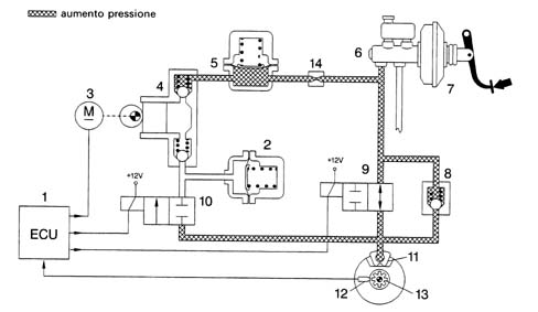
1 - Electronic control unit;
2 - Low pressure accumulator (reservoir);
5 - High pressure accumulator (damping chamber);
6 - Brake pump;
7 - Brake servo;
8 - Rapid pressure reduction valve;
9 - Pressurizing solenoid valve;
10 - Discharging solenoid valve;
3 - Recovery pump motor;
4 - Recovery pump;
11 - Brake caliper;
12 - Rpm sensor;
13 - Phonic wheel;
14 - Restricter.
Pressure maintenance stage
Pressure maintenance stage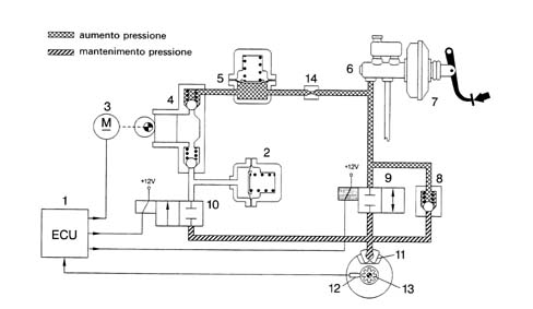
1 - Electronic control unit;
2 - Low pressure accumulator (reservoir);
3 - Recovery pump motor;
4 - Recovery pump;
5 - High pressure accumulator (damping chamber);
6 - Brake pump;
7 - Brake servo;
8 - Rapid pressure reduction valve;
9 - Pressurizing solenoid valve;
10 - Discharging solenoid valve;
11 - Brake caliper;
13 - Phonic wheel;
12 - Rpm sensor;
14 - Restricter.
Pressure reduction stage
Pressure reduction stage.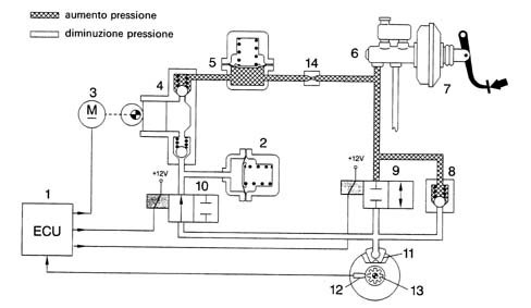
1 - Electronic control unit;
2 - Low pressure accumulator (reservoir);
3 - Recovery pump motor;
4 - Recovery pump;
5 - High pressure accumulator (damping chamber);
6 - Brake pump;
7 - Brake servo;
8 - Rapid pressure reduction valve;
9 - Pressurizing solenoid valve;
10 - Discharging solenoid valve;
11 - Brake caliper;
12 - Rpm sensor;
13 - Phonic wheel;
14 - Restricter.
Release of brake pedal
Release of brake pedal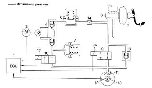
1 - Electronic control unit;
2 - Low pressure accumulator (reservoir);
3 - Recovery pump motor;
4 - Recovery pump;
5 - High pressure accumulator (damping chamber);
6 - Brake pump;
7 - Brake servo;
8 - Rapid pressure reduction valve;
9 - Pressurizing solenoid valve;
10 - Discharging solenoid valve;
11 - Brake caliper;
12 - Rpm sensor;
13 - Phonic wheel;
14 - Restricter.
EBD function (electronic brake-force distribution)
The introduction of the ABS 5.3 allows the distribution of the braking force between the front and rear axles using a specific electronic control unit function.With this in mind the electronic control unit continuously compares the speed of the front and rear wheels by means of speed sensors and operates the electro-hydraulic control unit to prevent the rear wheels from locking always making use of the maximum grip on the ground in all load conditions.The EBD function makes the use of a hydraulic load proportioning valve operating according to the load on the rear axle superfluous so it has been eliminated from the braking circuit.The graph below illustrates the operation of the EBD (curve D) in relation to the pressure in the braking system (curve A), the ideal pressure at the rear axle brakes (curve B) and the reduction in pressure at the rear axle brakes normally implemented by the traditional load proportioning valve (curve C).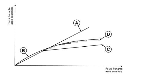
A - Distribution implemented by the brake system;
B - Ideal distribution;
C - Distribution implemented by the mechanical load proportioning valve;
D - EBD control.
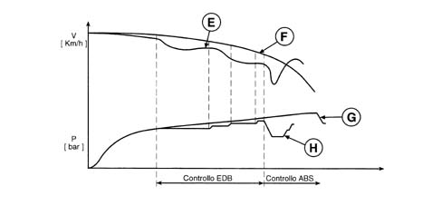
E - Rear wheel speed;
F - Front wheel speed;
G - Front wheel pressure;
H - Rear wheel pressure.
EOBD operation
The braking pressure for the rear axle wheels is implemented by the control unit in the same way as described for the operation of the ABS during the "Pressure maintenance stage" and the "Pressure reduction stage" with the difference being that the recovery pump is not activated and any excess hydraulic fluid is collected in the low pressure accumulator. The fluid returns to the supply circuit when the brakes are released.ASR function (anti-slip regulator)
In addition to ABS EBD, depending on the version, the New Ducato vehicles are fittedd in ASR systems.Specifications
A.S.R. CONTROL/REGULATION DEVICESThese carry out the functions of:- acceleration slipping adjustment (A.S.R.);
- locking the differential through action on the brakes (T.C.).
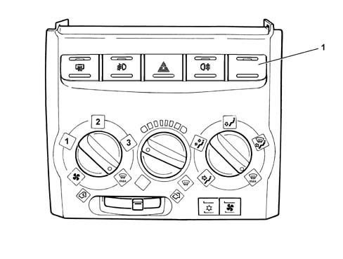
1 - A.S.R. on/off button
Composition
The system consists of:- a specific electronic control unit integrated with the electro-hydraulic control unit;
- an electro-hydraulic control unit that modulates the pressure acting on the brakes, independently of the action by the user, by means of twelve solenoid valves;
- four PASSIVE type sensors;
- specific wiring.
Operating principles
The system works through signals coming from the passive sensors, the brake lights switch and the ASR on/off button.It constantly compares the speed of the wheels on the same side of the vehicle (Right front with Right rear and Left front with Left rear) and when it detects a difference in speed, between the two wheels on the same side, of more than 2-6 km/h (intervention level) the ASR logic intervenes.The ABS/ASR control unit converses continuously with the engine management control unit via the C-CAN line.The ASR function is activated in all vehicle speed conditions, however, the intervention of the brakes is excluded above 80 km/h.Operating logics - Drive wheel slipping - Intervention times in good road surface grip conditions (asphalt)
Engine torque reduction by the engine management control unit through the alteration of the injection/ignition advances, 6/100 of a second after the slipping limit is exceeded.A further reduction in torque through a decrease in the throttle opening (by the engine management control unit through the motorized throttle body after 15/100 of a second).Intervention of the hydraulic system (braking force on the drive wheels) after 2/10 of a second.Operation in poor grip conditions
The system is capable of recognizing these conditions by comparing the acceleration of the drive wheels with the torque transmitted by the engine (engine load from the engine management control unit).The system behaves in the same way as for both drive wheels slipping in good road grip conditions (asphalt) and the intervention levels are at the lower limit.Slipping of one drive wheel only
Torque reduction by the engine management control unit through the alteration of the ignition advances, 6/100 of a second after the slipping limit is exceeded.A further reduction in torque through a decrease in the throttle opening (by the engine management control unit through the motorized throttle body after 15/100 of a second).Intervention of the hydraulic system, a braking action exerted on the wheel that it slipping to guarantee a resistive force on the side with poor grip (T.C.).This resistive force allows the differential to transmit an equal torque with good grip.Slipping of one wheel round bends in good grip conditions (asphalt)
The system recognizes the bend from the speed of the rear wheels (driven).The system implements the same operating mode described for the "Slipping of one drive wheel only" condition with the intervention levels at the upper limit. The torque reduction is applied gently.Slipping of one wheel round bends in poor grip conditions (snow-ice)
The system implements the same operating mode described for the "Slipping of one drive wheel only" condition with the intervention levels at the lower limit. The torque reduction is accentuated to ensure good side road holding.Vehicle unstable during deceleration with poor grip
The system recognizes this condition from the engine load, from the speed of the front and rear wheels and from the brake pedal sensor. In this case there is an increase in drive torque through the intervention of the engine management control unit opeing the motorized throttel to overcome the natural instability of the vehicle due to the engine braking torque in poor grip conditions.ASR system exclusion
If the system is excluded using the button, which is advisable when the vehicle is travelling over difficult surfaces (e.g. snow, ice, deep mud, sand or gravel) or when snow chains are fitted on the drive wheels, the ABS and EBD functions remain activated.Intervention levels
The different intervention levels between 2 and 6 km/h depend on environmental factors; some of the conditions have been described in the operating logics, others are:- high acceleration level;
- vehicle speed (see graph);
- type of tyres (normal or winter); with winter tyres and good grip, high intervention levels, e.g. with winter tyres and poor grip, low intervention levels. The system is capable of recognizing these conditions by comparing the acceleration of the drive wheels with the torque transmitted by the engine (engine load from the engine management control unit).
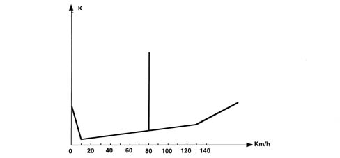
K - Slipping level
Operation of the hydraulic system
The electro-hydraulic unit on the version equipped with ASR has 4 additional solenoid valves.When the (normally closed) intake solenoid valve is activated, the additional quantity of fluid required to increase the pressure and brake the wheel(s) can be received.When the (normally open) solenoid valve is activated it allows the modulated pressure produced by the pump necessary for the intervention of the ASR to be maintained in the brake caliper-pump circuit.When the ASR TC function is not switched on, the electronic control unit:- does not supply the (N.C.) intake solenoid valve (2).
- does not supply the (N.A.) solenoid valve (3).
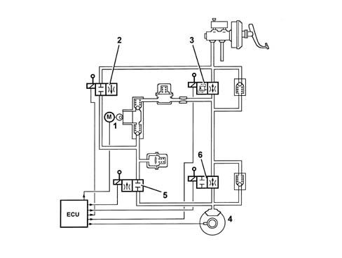
1 - Pump;
2 - Intake solenoid valve;
3 - Operating solenoid valve;
4 - Brake caliper;
5 - Discharging solenoid valve;
6 - Pressurizing solenoid valve.
BOSCH 5.3 ABS HYDRAULIC SYSTEM DIAGRAM
Dual circuit, cross-over braking circuit.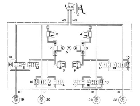
1 - Brake pump;
2 - Brake servo;
3 - High pressure accumulator (damping chamber);
4 - High pressure accumulator (damping chamber);
5 - Recovery pump motor;
6 - Recovery pump;
7 - Recovery pump;
8 - Low pressure accumulator (reservoir);
9 - Low pressure accumulator (reservoir);
10 - Rapid pressure reduction valve;
11 - Right rear pressurizing solenoid valve;
12 - Right rear discharging solenoid valve;
13 - Left front pressurizing solenoid valve;
14 - Left front discharging solenoid valve;
15 - Right front pressurizing solenoid valve;
16 - Right front discharging solenoid valve;
17 - Left rear pressurizing solenoid valve;
18 - Left rear discharging solenoid valve;
19 - Right rear drum brake;
20 - Left front disc brake;
21 - Right front disc brake;
22 - Left rear drum brake;
MC1 - Supply connector for brake pump 1st stage;
MC1 - Supply connector for brake pump 2nd stage;
RR - Supply connector at right rear cylinder;
LF - Supply connector to left front brake caliper;
RF - Supply connector to right front brake caliper;
LR - Supply connector at left rear cylinder;
BOSCH 5.3 ABS WIRING DIAGRAM
Bosch 5.3 ABS wiring diagram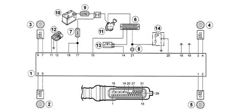
1 - Electronic control unit;
2 - Left rear rpm sensor (LR);
3 - Left front rpm sensor (LF);
4 - Right front rpm sensor (RF);
5 - Right rear rpm sensor (RR);
6 - Fuse box (10A protective fuse);
7 - 60A Protective fuses;
8 - Preheating warning light in instrument panel;
9 - 175A maxi fuse;
10 - Battery;
11 - Ignition switch;
12 - Tester input;
13 - Brake light switch;
14 - ABS warning light.
| Pin | Destination |
|---|---|
| 1 | To the right rear rpm sensor |
| 2 | To the right rear rpm sensor |
| 3 | To the right front rpm sensor |
| 4 | To the right front rpm sensor |
| 5 | Spare |
| 6 | To the left front rpm sensor |
| 7 | To the left front rpm sensor |
| 8 | To the left rear rpm sensor |
| 9 | To the left rear rpm sensor |
| 10 | Spare |
| 11 | To the diagnostic socket |
| 12 | Spare |
| 13 | Spare |
| 14 | To the brake lights switch |
| 15 | +15 Supply |
| 16 | To the earth |
| 17 | +30 Supply |
| 18 | +30 Supply |
| 19 | To the earth |
| 20 | ABS failure warning light |
| 21 | EBD failure warning light |
| 22 | Spare |
| 23 | Spare |
| 24 | Spare |
| 25 | Spare |
| 26 | Spare |
| 27 | Spare |
| 28 | ASR warning light |
| 29 | CAN L |
| 30 | CAN H |
| 31 | ASR switch |
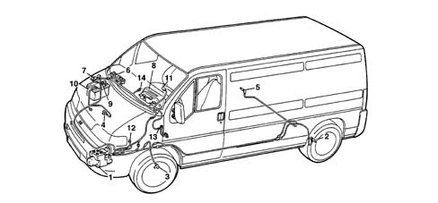
1 - Electronic control unit;
2 - Left rear rpm sensor;
3 - Left front rpm sensor (LF);
4 - Right front rpm sensor (RF);
5 - Right rear rpm sensor (RR);
6 - Fuse box (10A protective fuse);
7 - 60A Protective fuses;
8 - Braking failure warning light;
9 - 175A maxi fuse;
10 - Battery;
11 - Ignition switch;
12 - Tester input;
13 - Brake light switch;
14 - ABS warning light.