Descriptions
APPLICATION
Engines: 2.0 16V, 2.0 JTD 8V, 2.3 JTD 16V, 2.8 JTD 8V
SPECIFICATIONS
The additional heater is optional on all versions of this vehicle.The vehicle may optionally be fitted with two different independent heater versions: one fully automatic, the other programmable.Programmable version
The Webasto Thermo Top C suppelementary heater is fully independent of engine operation and allows:- pre-heating of engine coolant
- reduction of the time the engine takes to warm up
- passenger compartment heating with the engine off
- elimination of ice and condensation from windows
- less engine wear
- a reduction in harmful emissions
- improved comfort
- increased safety
Automatic version
The automatic version, without digital timer, works completely independently of the engine.Unlike the programmable version, this version operates automatically whenever the key is turned on, according to the temperature recorded.OPERATING DESCRIPTION FOR PROGRAMMABLE VERSION
System description
The system consists of:- A heating unit that essentially consists of a diesel burner (1);
- Integral outdoor air temperature sensor and integral electric pump for engine coolant circulation.
- Exhaust gas pipe with silencer (2).
- Electric fuel metering pump (7).
- Fuel delivery pipe (5).
- A heat exchanger, coaxial to the burner, connected via pipes (3) to the vehicle coolant system;
- An output pipe (4) from the metering pump to the burner;
- Passenger compartment heating/ventilation unit (8) may be started automatically via the heater unit control unit;
- An electronic control unit for controlling and regulating auxiliary heater system functions built into the heater unit;
- A digital timer (9) for programming the heater activation time or for immediate manual activation.
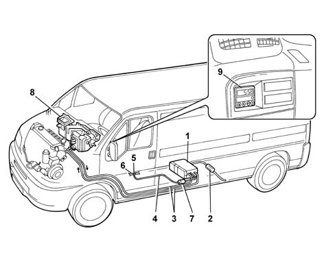
1 - Independent heater unit.
2 - Exhaust silencer.
3 - Coolant pipes
4 - Fuel delivery pipe.
5 - Three-way connector
6 - Diesel return pipe from injection pump to reservoir.
7 - Heater fuel metering pump.
8 - Heating/ventilation unit.
9 - Digital timer.
- Interface with the engine cooling system: the coolant leaving the power unit is directed to the heater and is returned to the circuit by a dedicated electric pump.
- Interface with the fuel supply system: The heater burner is supplied with fuel, taken directly from the tank by means of an electric pump and conveyed in a special pipe.
- Interface with the electrical system: the heater is fitted with dedicated connectors which ensure the supply for the two electric pumps (fuel and coolant), the burner heater plug and the management control unit.
Digital timer operation
The heater may operate automatically, if programmed using the digital timer, or manually by pressing the "immediate heating" key on the timer.For the system to operate, the passenger compartment heating/ventilation unit air temperature adjustment knob must be in "warm air" position, while the passenger compartment heating/ventilation unit fan speed adjustment knob must be set to "2".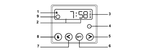
1 - Heater cycle warning light.
2 - Display lighting.
3 - Clock preselection recall number.
4 - Clock button.
5 - Hour forward adjustment button.
6 - Program selection button.
7 - Hour back adjustment button.
8 - Immediate heating activation button.
9 - Time adjustment/reading warning light
- press button (4);
- warning light (9) appears on the display and the display lights up
- to set the time, press buttons (5) and (7) within 10 seconds to select the exact time;
DESCRIPTION OF THE COMPONENTS
Description of the heater unit
The heater is the central unit of the system. It ensures the heating of the engine fluid and the management of the system operating parameters.The heater includes the various components which are vital for the operation of the system.The central part of the unit consists of a diesel burner (1) that contains the flame and a coaxial heat exchanger (2) that heats the water circulating round the system.The following are also present:- an electric coolant circulation pump (3) that allows coolant to circulate through the system with the engine off.
- A glow plug (4) to ignite combustion,
- A combustion air fan (5) that draws air in from an external pipe to supply the air required for combustion.
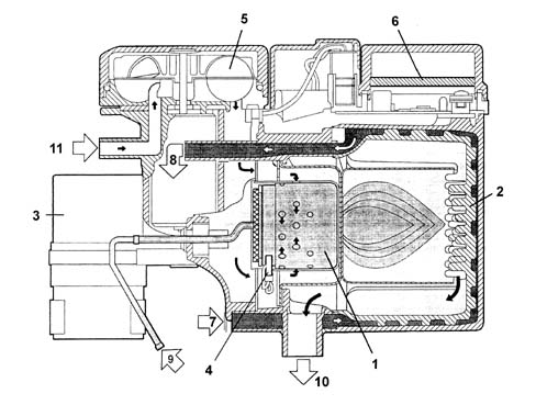
1 - Burner
2 - Heat exchanger
3 - Coolant circulation pump
4 - Glow plug
5 - Combustion air fan
6 - Electronic control unit
7 - Combustion air intake
8 - Coolant intake
9 - Diesel intake
10 - Coolant outlet
11 - Exhaust gas outlet
SYSTEM OPERATING LOGIC
Operation of programmable device
The Webasto heater system operates whether the engine is on or off. It operates fully automatically to heat, maintain the temperature in and drive fluid through the system for a preset time period to ensure temperature conditions in the passenger compartment and engine are optimum upon start-up.The device may start to operate automatically on the basis of a program set on a digital timer or manually by pressing the "immediate heating" button on the timer.In both cases, the electronic control unit operates the coolant circulation pump, glow plug and combustion air intake fan upon activation.Once the glow plug preheating period of 30 seconds has elapsed, the fuel metering pump is operated and combustion is triggered at ignition power.The presence of a flame, detected by the photocell, causes:- glow plug deactivation and, to stabilise combustion,
- a 20 second reduction of fuel pump and combustion air fan power to a reduced mode
Releasing the heater after shut-down due to a fault
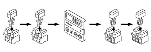
If the heater overheats or if it is deactivated three times due to a fault, carry out the heater release procedure after removing the source of the fault.Turn the heater off and on as shown in the figure.