Connect is the infotelematic system fitted to this vehicle. It interacts with the user to facilitate driving and make life inside the passenger compartment as pleasant as possible.The Connect system is not fitted to the vehicle as standard but is available as an option.
COMPOSITION
System architecture
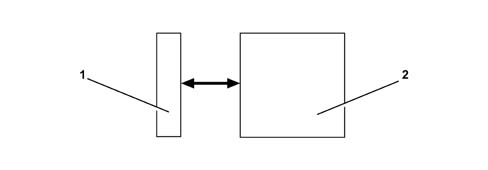
The Connect system consists of:
FRONT PANEL (1), which acts as the physical interface between system and user. It incorporates a display, a numerical keypad and function keys.
SILVER BOX (2), containing the motherboard, radio module, GSM module and Audio CD player/CD ROM drive
Connect configurations
The Connect system is also available in the following configurations: LEVEL 1 (L1), LEVEL 2 (L2), LEVEL 3 (L3), LEVEL 4 (L4).L1, includes the following modules:
Radio
CD player
GSM Module
GPS Module
Assistance services
192x80 pixel LCD graphic display
External CD CHANGER system (if present)
Options: WAP protocol + MP3
L2, includes the following modules:
Radio
CD player
GPS Module
Independent navigation with pictograms
192x80 pixel LCD graphic display
External CD CHANGER system (if present)
L3, includes the following modules:
Radio
CD player
GPS Module
GSM Module
Independent navigation with pictograms
Targasys Services
192x80 pixel LCD graphic display
External CD CHANGER system (if present)
Options: WAP protocol + MP3
L4, includes the following modules:
Radio
CD player
GPS Module
GSM Module
Independent navigation with maps
Targasys Services
5" TFT (Thin Film Transistor) display
Options: Telepass information display (if present), external CD CHANGER system (if present), built-in voice recognition module, MP3
Description of internal modules
Various different modules make up the system for providing services or obtaining information.
CD player
The CD drive can read the and manage the audio CD to play music CDs and read CD ROMs.Connect is also designed to be connected to an external CD Changer and to accept analogue audio output. The device for which it is designed as a Blaupunkt CD changer.The CD Changer is not supplied as standard with the Connect system.
GSM phone
Connect L1 and L4 are equipped with a Dual Band module and Sim Card reader (that allows the user the insert a SIM Card).The SIM reader is designed for an ISO format SIM Card.A plug-in format Sim Card can be used only with an ISO adaptor.
Radio module
The module comprises:
Tuner
Audio power amplifier
Control software
Interface for external CD changer
Interface for external audio inputs
AUDIO INPUTS:
Phone audio (analogue - mono)
Navigator audio (analogue - mono)
CD-DA audio player inside Connect
Audio for CD-Changer external to Connect (analogue - stereo [from ISO connector])
AUDIO OUTPUTS:
Output with 4 amplified analogue audio channels.
Preparation for interface with BOSE system.
AUDIO SOURCE MANAGEMENTThe selected source is mixed in the navigator when fitted and in use.Audio sources may be heard from all speakers.
Description of controls
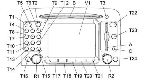
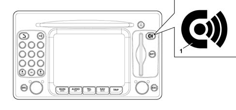
The Connect front panel, shown in the following figure (Fig. 2), houses the keys that allow the user to control the system.Some keys perform multiple functions that depend on the active system operating conditions.Activation of the selected function is controlled, in some cases, by the length of time for which the key is pressed (short or long push) as described in the following table.Some Connect functions are managed by controls on the steering wheel.Connect is designed to receive certain voltage levels (4 levels per channel), each corresponding to depression of a key on the steering wheel, as input to two separate channels.
Key
Short press on key (less than 1 second)
Long press on key (more than 1 second)
T4 - T5 - T6 - T7 - T8 - T9
Numbers "1", "2", "3", "4", "5", "6" on phone keypad. Stored station recall
Storing station nos. 1-2-3-4-5-6
T10
Number 7 on phone keypad. Select previous CD on CD-Changer (if installed)
-
T11
Number 8 on phone keypad
-
T12
Number 9 on phone keypad. Select next CD on CD-Changer (if installed)
-
T14
Number 0 on phone keypad. Audio CD Play/Stop
Audio CD play pause
T13
(*) symbol on phone keypad. Radio mode: search for first available station with lower frequency. CD mode: select previous track
-
T15
(#) symbol on phone keypad. Radio mode: search for first available station with higher frequency. CD mode: select next track
-
T1
Send phone cal Accept incoming call End current phone call
This knob is known as an encoder. Select function (turn knob). Confirm selected function (pres knob). Activate drop-down menu (press knob with MAIN screen)
-
T24 ESC
Exit selected screen. Return to next menu level up and cancel unconfirmed functions
-
T23 RPT
Repeat last navigation voice instruction
-
T22 Connect
Display emergency or assistance call menu
-
T3
Eject navigation CD-ROM or audio CD
-
B
SIM phone card slot
-
A
Navigation or Audio CD slot
-
C
- Optical sensor for automatic switching of display lighting between night and day settings.
Interfaces
CD Charger
CONNECT all levels) is also designed to be connected to an external CD Changer and to accept analogue audio output.The interface consists of:
The CONNECT system is designed to interface with the hi-fi system.The interface consists of:
Interface with CAN network (Option)
The CONNECT system is designed to interface components with a CAN bus.
Video input
CONNECT is designed to interface with an external video source (parking TV camera) so that it can show imagines on the displayThe interface is an NTSC-format composite video type.Two pins of the MQS connector are dedicated to this interface. These are connected to the video signal and reference (cable and shield).
PC interface
CONNECT is designed to interface with a PC via a RS232 serial port.
Connect Electrical Absorptions
CONNECT power uptakes during the possible operating modes are as follows:
CONNECT OFF: Imax = 3.2 mA / 13.5V
CONNECT Stand-By: Imax = 1A / 13.5V
CONNECT ON: 1.2A / 13.5V %lt; I %lt; 7A / 13.5V
Minimum and maximum power uptakes shown with CONNECT ON are determined by the following operating conditions:
Screen off, GSM on, radio off: 1.2A / 13.5V
Screen on, GSM on, radio off: 2A / 13.5V
Contribution of radio on: 5A / 13.5V
Connectors
Connector arrangement
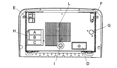
The arrangement of connectors on the rear of Connect is shown below.
A - Radio connector
B - Radio connector
C - Radio connector
D - Service connector
E - GSM aerial connector
F - GPS aerial connector
G - Radio aerial connector
H - 10 Amp fuse
I - Locating pin
L - Heat dissipator
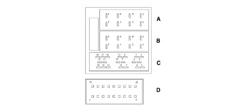
PIN OUT
Connect connector pin-out.8 pin connector (A)
Pin
Function
1
n.c.
2
n.u.
3
n.c.
4
Key on input (+Key)
5
12 V for aerial amplifier
6
n.c.
7
12 V permanent
8
Power supply GND
8 pin connector (B)
Pin
Function
1
+ RH rear speaker
2
- RH rear speaker
3
+ RH front speaker
4
- RH front speaker
5
+ LH front speaker
6
- LH front speaker
7
+ LH rear speaker
8
- LH rear speaker
20 pin connector (C)
Pin
Function
1
n.c.
2
n.c.
3
n.c.
4
n.c.
5
n.c.
6
n.c.
7
Tx [serial RS232]
8
Rx [serial RS232]
9
n.c.
10
Input 1 for Keys on Steering wheel
11
Input 2 for Keys on Steering wheel
12
Steering wheel Key reference
13
n.u.
14
n.u.
15
n.u.
16
n.u.
17
n.u.
18
n.u.
19
n.u.
20
n.u.
18 pin connector (D)
Pin
Function
1
DCD [serial RS232]
2
Telepass serial
3
Reversing Signal Input
4
Composite video earth screen
5
Composite video in
6
TV camera recognition signal
7
DTR [serial RS232]
8
DSR [serial RS232]
9
Microphone input
10
RTS [serial RS232]
11
Odometer Signal Input
12
GND [serial RS232]
13
n.c.
14
Power source 12V to parking TV camera
15
+light signal input
16
CTS [serial RS232]
17
RI [serial RS232]
18
Microphone earth
Aerials
The Connect system is fitted with two aerials:
GPS aerial located in a central position in the joint area between windscreen and ceiling.
Dual-mode rod aerial located on the vehicle exterior on the upper part of the roof. This aerial is used for the radio and GSM module.
Protection against overheating
Telematic system components come with protection against overheating. This cuts off operation when module temperature exceeds a set limit.In this case, the function activated by the module that has reached the temperature limit is deactivated and a warning message appears on the display.The user must wait for module temperature to drop below this limit before resuming the interrupted function. This is indicated by the message disappearing from the display followed by function reactivation.Otherwise, press the ESC key to exit from the screen with the message immediately and activate a different function.Connect module limit temperatures are shown in the following table.
COMPONENT
OPERATING LIMIT
Radio
85°C (logic components) 120°C (power terminal)
CD player
70°C
GSM
70°C
GPS/Motherboard
85°C
Limit temperature may be considered independent of the radio volume. (power dissipated is independent of volume).CD tests demonstrated only player operation. Optical medium (disc) lifecycle drops significantly at temperatures approaching a 55°C.Possible CONNECT statuses from the viewpoint of power supply and operation in general are as follows: OFF Status, Normal Status, StandBy Status
Power supply management
The system may be in one of the following conditions:
OFF status with all functions disabled;
NORMAL status with all functions active or activatable;
STAND-BY status, with functions partially active and screen dark.
OFF status
All Connect functions are disabled and the various hardware modules are not supplied with power.
NORMAL status
The Connect system is fully active and all system functions are managed in accordance with the system configuration.Internal modules are operational, as are the internal communication lines.The system configuration is stored when this status is left. It is then restored when the status is resumed.
STAND-BY status
While in this mode, the Connect system is partly active but looks exactly as though it were OFF to the user.Network localisation and management modules remain active at internal module level.The following modules are deactivated: Telephone, Radio, Audio, Audio CD and CDC, Voice Recognition, Voice synthesis and Navigation system.The electrical statuses described earlier are determined by the following actions:
activation
deactivation
stand-by.
Ignition
The system is activated automatically when the ignition key is turned to MAR. When the system is turned on, the status active prior to the last deactivation (normal or stand-by) is restoredWhen the ignition key is turned to OFF or removed, the system can be turned on by pressing the encode ON/OFF R1 (See Fig. 2), or the Connect key (enter the PIN code to use the phone).
Deactivation
If the system is on (NORMAL or STAND-BY status), it may be turned off by removing the ignition key.The Connect unit stores the system configuration in its memory when it is turned off.Deactivation is delayed if a phone call or emergency call is in progress or if the system is changing the voice command language. In this case, the Connect unit turns itself automatically when the call is terminated by the user (if the call lasts longer than 20 minutes) or 20 minutes after key off (if the call lasts less than 20 minutes).If the Connect unit is turned on with key off (+Key inactive) via the ON/OFF encoder or Connect key, it can be turned off by pressing the ON/OFF encoder again. Otherwise it is turned off automatically after 20 minutes to save battery charge.
Stand-by
During operation, the system may be by-passed to stand-by by a long press on the MAIN key. This operating condition corresponds to a dark screen and volume off. The system continues to work in stand-by mode, however, because the phone remains ready to receive.If the limit of one active function is exceeded during stand-by, an appropirate warning message is displayed.To restore the system to normal operating mode, press the MAIN key or Connect key briefly for a "Service call" (the PIN code must be entered to use the phone).
Signals
Because this vehicle is not equipped with a CAN network, the main information must be transmitted to Connect by means of direct physical signals.These signals are:
key signal: turns on the Connect unit when the key is turned On
Reverse engaged, to identify vehicle direction of motion.
Odometer, to calculate the distance travelled by the vehicle.
Light control, to modify screen lighting.
Menu function selection
The various Connect operating modes give access to different menus. These contain functions that are divided, in turn, into submenusThe selection and confirmation methods are, however, the same for all the various menu functions and are as shown below.To return to the previous screen from a submenu or to leave the various operating modes, press the ESC key.
Selecting a function
To select a menu function shown on the display, turn encoder R1 (see Fig. 2) in one direction or another until the selected function is highlighted.
Confirming the function selected
Press encoder R2 (see Fig. 2) to confirm the selected function
Selecting operating mode
Select the operating mode by pressing one of the following keys (see Fig. 2):
MAIN key: MAIN SCREEN
AUDIO key: RADIO WITH CD PLAYER
TEL key: TELEPHONE
key T2: VOICE COMMANDS
NAV key: NAVIGATOR
TRIP key: ON-BOARD COMPUTER
CONNECT key: TARGAsys SERVICES.
A menu is shown on the display for each operating mode
FUNCTIONS
MAIN screen
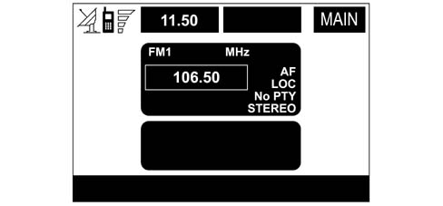
The main screen is used to display the most important system data.The MAIN screen appears when the ignition key is turned ON or key T17 "MAIN/DARK" key (see Fig. 2) is pressed. It provides information on the active functions.
SET-UP function
Activation of SET UP menu
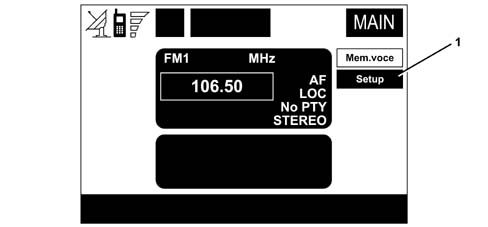
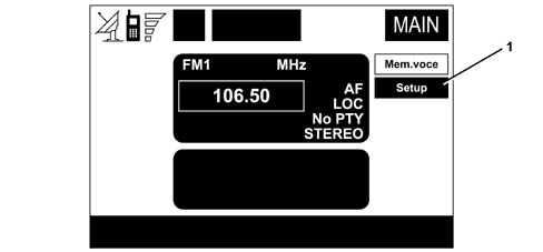
To activate the Setup menu:
display the MAIN page
press the encoder to the right to display the items "Store item, Setup",
select the item "Setup" with the encoder (1).
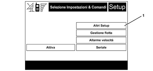
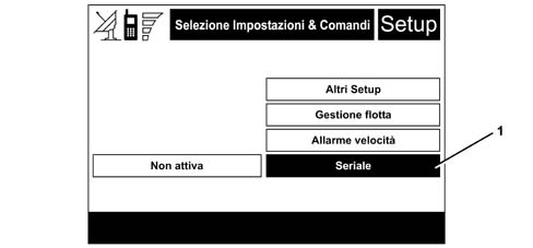
"Other SETUPS"
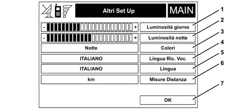
Select the "Other Setups" item on the screen shown below.The page shown in the following figure will be displayed.
1 - Daytime brightness
4 - Rec. language Voc
6 -Distance measurement
7 - OK
5 - Language
3 - Colours
2 - Night-time brightness
1. DAYTIME BRIGHTNESS"Daytime brightness" is used to adjust screen brightness when the daytime colour selection is active or when Automatic colour selection is active when Automatic refers to the daytime conditions. (dusk night brightness).Select the item to alter "Daytime brightness"Turn the encoder to alter screen brightness.The indicator bar will alter the number of bars lit.2. NIGHT-TIME BRIGHTNESS"Night-time brightness" is used to adjust screen brightness when the night-time colour selection is active or when Automatic colour selection is active when Automatic refers to the night-time conditions. (dusk day brightness).Select the item to alter "Night-time brightness"Turn the encoder to alter screen brightness.The indicator bar will then alter the number of bars lit.3. COLOURSThis key is used to activate Day, Night or Automatic colours.Turn the encoder to select the item "Colours". A drop-down menu appears that can be used to select the required mode."Automatic" adjustment is dependent on exterior lighting stalk position:
EXTERIOR LIGHTS OFF: Lighting is daytime.
EXTERIOR LIGHTS ON: Lighting is daytime if passenger compartment is strongly lit (driving by daytiem with exterior lights on) and night-time if passenger compartment is weakly lit (driving by night).
4. VOICE REC. LANGUAGEThis items is allowed to select the language used for voice recognition and navigation system messages.The possible choices are contained in a drop-down menuThe drop-down menu does not display all possible choices simultaneously, only those allowed in the available space. Turn encoder R2 (see Fig. 2) to scroll through all possible choices on the drop-down menu.If you decide to change the voice recognition language, the system asks you to insert a navigation CD once you have confirmed the menu selection by pressing the encoder R2 (see Fig. 2). If the CD is already inserted, the system goes off-line for a few seconds and phone calls are terminated.5. LANGUAGEThis item allows you to change the language of messages displayed on the screen.The drop-down menu does not display all possible choices simultaneously, only those allowed in the available space. Turn encoder R2 (see Fig. 2) to scroll through all possible choices on the drop-down menu.This selection becomes active only after confirming via the OK key.6. DISTANCE MEASUREMENTSThis item allows you to select km or mile mode.Turn the encoder to select "Distance Measurement": the mode changes automatically.7. EXITAfter setting, select OK to make the settings operational.
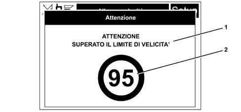
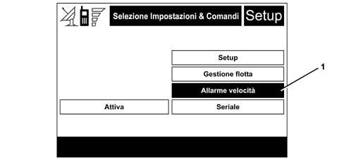
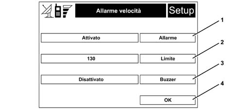
Fleet management, speed alarm, serial
These functions are described in greater detail in the relevant paragraphs.
Audio function
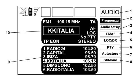
The audio system is activated by a short press on key T18 "AUDIO/OFF". This provides access to the main functions, which are shown in the following figure.
1 - Frequency
2 - Audio Setup
3 - TA/AF
4 - LOC/DX
5 - PTY
6 - Autostore
7 - St/Mono
Hold the key down for longer with the audio system operational and any operating mode active to activate the MUTE function: while in this mode, the radio will go off and the message "Audio OFF" will appear on the display. - To turn the radio back on, press the key briefly to reactivate the audio function with associated screen.The telematic unit audio system manages the following:
RDS radio with FM/AM reception;
Compact Disc player;
CD-Changer (if installed);
Equaliser (except for versions with BOSE HI-FI system).
Press the SRC key repeatedly to display the available audio sources cyclically:
Radio (FM1, FM2, FM3, LW, MW)
CD (if a CD is inserted)
CD-Changer (if installed).
The sound source is automatically modified in one of the following cases:
traffic information transmission, if the TA function is active and if tuned to an enabled station (TP)
phone call
phone call reception
voice recognition function activation
CD insertion
Possible audio sources include standard sources (Radio Tuner, Audio CD and CD Changer) - described in detail in the rest of the chapter, alarms and Traffic Announcements, treated as separate functions, and sources linkd to other modules, namely Telephone, phone ring tone (Ringing), Voice Recognition Unit and Voice Synthesis for navigation.The following table shows possible source combinations.
SOURCES IN USE SIMULTANEOUSLY
Standard
Telephone
Ringing
Voice Recognition
PTY31_Al
Navigation
ACTIVE SOURCE
Standard
X
X
Telephone
X
X
Ringing
X
Voice Recognition
X
PTY31_Al
X
X
Navigation
X
X
X
X
"Audio setup" function (AUDIO SETTINGS)
The audio parameters described in this paragraph may be activated or set with all the audio sources (Radio, CD, CD-Changer).Select or confirm the Audio setup function from the main menu of one of the audio sources by turning and pressing encoder R2 (see "Control description" paragraph).The following settings are available:
Treble : treble adjustment
Bass: bass adjustment
Loudness: improves sound level during low volume playing by increasing bass and treble
Equalizer: selection of preset equalisation levels
Equal. Man: manual adjustment of equaliser frequency bands (deactivates treble and bass settings). The display shows the message USER when a customised equaliser adjustment is set.
SDV used to adjust radio volume to vehicle speed automatically.
Bal/Fader: adjustment of sound distribution inside the passenger compartment. "Balance" adjusts sound distribution between right and left passenger compartment speakers. "Fader" adjusts sound distribution between front and rear speakers.
Select and confirm "OK" to return to the previous screen and store the new settings. Press the ESC key to return to the previous screen and restore the previously-stored settings.
Radio mode
Select the Radio source using the SRC key to display the following functions:
Frequency
Audio setup
TA/AF
LOC/DX
PTY
Autostore
St./Mono.
The radio is always ready to receive stations in RDS (Radio Data System) mode."FREQUENCY" FUNCTIONThis function allows manual or automatic tuning/storage of radio stations.If the "TA" (traffic information) or "PTY" function is active during automatic tuning, the tuner looks only for stations that broadcast traffic news or PTY stations."TA" FUNCTIONThis function enables the radio to receive traffic news transmitted by some FM stations. The message "TP" appears on the display in this case.To activate/deactivate the TA (Traffic Announcement) function, press the knob repeatedly after selecting the TA/AF function.TA/AF functions are activated cyclically by short presses on the knob and occur as follows: AF - TA - TA and AF - both functions off - AF ¿etc.The message "TA" appears on the display when the TA function is activated.Listening conditions and display messages are as follows:
TA and TP: if the radio is tuned to a station broadcasting traffic information and the traffic information function is active
TP: if the radio is tuned to a station broadcasting traffic information and the traffic information function is inactive
TA: the traffic information function is active but the radio is tuned to a station that does not broadcast traffic information
TA and TP not present on display: the radio is tuned to a station that does not broadcast traffic information and the traffic information function is inactive.
With the TA function active, it is possible to:
search only for RDS stations that broadcast in FM and are enabled to broadcast traffic information;
Receive traffic information even when the CD player is in operation;
Receive traffic information at a minimum preset volume even with the radio volume zeroed or the system set to stand-by.
when listening a CD, an automatic search is carried out for another station enabled to transmit traffic information
when listening to the radio, an acoustic signal is emitted to warn that traffic information can no longer be received; the signal is cut off by tuning to a station that can broadcast information or by deactivating the TA function
"AF" FUNCTIONThis function enables reception of radio stations in RDS (Radio Data System) modeWhen in RDS mode, the radio can work with:
AF ON: active search for alternative frequencies;
AF OFF: search for alternative frequencies deactivated.
When the broadcasting RDS station signal weakens, two things may happen:
In AF ON mode, the RDS system activates an automatic search for optimum frequencies for the selected station and the radio then tunes automatically to the station with the strongest signal broadcasting the same programme. Passengers can therefore continue to listen to the selected station throughout the trip without altering the frequency when the area changes. It must naturally be possible to receive the broadcasting station in the vehicle's current area.
In AF OFF mode, the radio does not tune automatically to the strongest station and the station must be searched for manually by means of the tuning keys.
Press the knob repeatedly to activate/deactivate the AF function after selecting the TA/AF function.TA/AF functions are activated cyclically by short presses on the knob and occur as follows:
AF - TA - TA and AF - both functions off - AF ¿etc.
The message "AF" appears on the display when the AF function is activated.
The message RDS (if available) remains on the display.
LOC/DX FUNCTIONThis function is used to alter the senstivity of the autamatic radio station search. When low sensitivity "LOC" is set, only stations with excellent reception are sought; when high sensitivity "DX" is set, all stations are sought. When in an area where many stations are present and you wish to select those with the strongest signal, set low sensitivity "LOC".To select between low or high tuner sensitivity, press the knob repeatedly after selecting the function "LOC/DX". The sensitivity setting code is shown on the display:
LOC = low sensitivity;
DX = high sensitivity.
FUNZIONE "PTY"The PTY (Program Type) is used to give preference to stations that broadcast programmes classified according to PTY type. The radio contains a list of preset Programme Types for selection. Select the PTY function and confirm with the knob to access a PTY programme list. The display will show a list of PTY programmes and the subject of the last broadcasting station (e.g. NEWS). Turn the knob to scroll through the list of PTY programmes. To select a programme type, press the knob after making a selection.The FM band must be selected before the PTY function can be activated.If the station does not broadcast in PTY mode, the message "NO-PTY" appears on the display for 5 seconds.After 2 seconds, the station name or frequency is displayed."EON" (Enhanced Other Network) FUNCTIONCircuits active in certain countries group together several stations enabled to broadcast traffic information. In this case, the programmed being broadcast by the current station will be temporarily suspended to receive traffic information (only with TA function active) whenever this is broadcast by one of the stations on the same circuit. When the tuned station belongs to an EON circuit, the display will show the message "EON"."AUTOSTORE" FUNCTIONThis function allows automatic radio station storage.When this function is active, the radio automatically stores stations with the strongest signal in decreasing order of signal intensity within the tuned frequency band:
6 stations in the FM1, FM2 or FM3 band or
6 stations in the MW band or
6 stations in the LW band.
If the TA (traffic information) function is active, only stations that broadcast traffic information are stored. This function may be acivated even while listening to a CD.The message "Autostore" will appear on the display during the automatic storage stage. Deactivate the "Autostore" function by pressing the ESC key to interrupt the automatic storage process; the radio will re-tune to the station broadcasting before the funtion was activated.Station signals that are currently strongest within the selected band are automatically stored on preset keys T4, T5, T6, T7, T8, T9 (see Fig.2) . Once storage is complete, the radio will automatically tune to the first FM1 station corresponding to the frequency stored for preseletion key "1".Each station will be stored once only, except in the case of regional programmes that could be stored twice under certain circumstances.Sometimes the Autostore function may not be able to find 6 stations with strong signals. In this case, only the stations found will be stored."ST./MONO" FUNCTIONThis function allows stereo reception of stations to be activated/deactivated by pressing the knob after selecting the St./Mono function. When stereo reception is activated, the displays shows the message "STEREO", while the message "MONO" appears when it is deactivated.When the tuned station frequency is weak, it is advisable to activate the "MONO" function to improve listening quality.
CD MODE
AUDIO CD FUNCTIONThe Audio CD source and function can be selected from amongst the various audio sources on the Connect unit.AUDIO CD COMMANDSThe commands are as follows:
Play: begins playing an audio track from the current disc position.
Available playing modes:
Random : a random track sequence is made available for audio playing
Repeat : a single track or entire sequence is repeated until the user specifically stops the sequence.
Pause : playing is suspended and the optical pick up stays on the current track. This function is called up by means of a long press on key T14 (see "Control description" paragraph).
Stop : playing is suspended and the optical pick up moves to the beginning of the track sequence.
Skip : the optical pick up moves directly to the beginning of the track before or after the current track.
Scan: select this control to play the first part of all the tracks on the CD.
Eject: use to eject the CD.
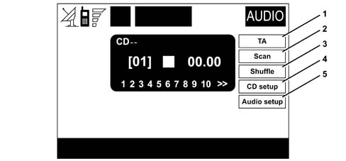
Select the CD source using the SRC key to display the following functions (see figure below):
1 - TA
2 - Scan
3 - Shuffle
4 - CD setup
5 - Audio setup
If the CD is not inserted in the player, the message "No CD-DA" appears on the display.When the CD source is selected, playing begins from the last track played previously or the first track when the CD is inserted. To listen to the previous or next CD track, press the < < or > > keys.The upper part of the display shows the current track number, the functions activated and the time passed (total or partial).If the current CD is not legible or is not an audio CD, the message "CD Error" appears on the display.The lower part of the display shows the total CD listening time.To suspend CD playing, press the PLAY / STOP / PAUSE key briefly. To resume CD playing, press the PLAY / STOP / PAUSE key briefly again. To pause the CD for longer, press the PLAY / STOP / PAUSE key for longer.Press key T3 "EJECT" (see Fig.2) to remove the CD from its slot."TA" FUNCTIONUsed to activate/deactivate the TA (Traffic Announcement) function while listening to a CD. Press the knob after selecting the function (see relevant paragraph in the "RADIO MODE" chapter)."SCAN" FUNCTIONWhen this function is active, all CD tracks are played for about 10 seconds in the order that they appear on the CD.The "Scan" function is automatically deactivated when the "Shuffle" function is activated."SHUFFLE" FUNCTIONThe CD tracks are played in random order when this function is activated.The "Shuffle" function is automatically deactivated when the "Scan" function is activated."CD SETUP" MENUSelect and activate "CD setup" using the knob to access the CD function menu:
Display this function so select the type of CD operation information to show on the display.
The repeat control is used to activate/deactivate continuous repetition of the current track or the entire CD.
OK
"AUDIO SETUP" MENUSee corresponding paragraph
CDC (external CD-CHANGER) mode
if a multiple CD player is fitted, select the CDC (CD-Changer) source using the SRC key. The following functions will be displayed:
TA
Scan
Shuffle
CDC setup
Audio setup.
The above functions are managed in the same way as in "CD mode".
Navigation function
The navigation system built into the Connect unit helps the driver reach a selected destination by means of visual and acoustic instructions. The navigation system is flexible to use because it allows the driver to call up pre-programmed destinations or reference points such as hotels, historical sights, public organisations, fuel stations or Manufacturer's Authorise Serviced Outlets.The navigation function is available on all Connect configurations except Level 1.On the available versions, map navigation can be displayed only on Connect level 4, fitted with a 5" TFT display. - A pictogram navigation system is used for other versions, fitted with LCD graphic displays.The navigation system is fully managed by the telematic system. The only operations required is therefore to replace the navigation CD-ROM to obtain a map of a different area or an up-to-date map.
Vehicle location
The essential information required by the system in order to set navigation routes is the vehicle's position on the world's surface.The accuracy with which the system calculates the vehicle's position significantly determines the consistency of navigation routes with the earth's topography and road networks.For this purpose, the system uses a GPS (Global Positioning System) aided by the interaction of certain sensors.The GPS on the vehicle is equipped with an aerial and a reception module built into the telematic system. This system dynamically processes satellite signals, reversing signals, information from a gyroscope built into the navigation computer and signals from the odometer. These are all integrated with current vehicle position.Signals from the odometer are used to determine vehicle displacement, the reversing sensor identifies the direction of motion and the gyroscope indicates the vehicle's angular displacement (turns, direction reversals).The system constantly compares data from the odometer, reversing sensor, GPS aerial and gyroscope in order to compensate automatically for any event that could in some way lead to a false position reading.The following GPS measurements are used inside the NIT navigation system:
Vehicle position estimation (Latitude, Longitude in radiants, Height in metres).
Vehicle speed in m/s along the south-north / east-west axes.
Estimate of GPS position error.
Quality data relating to input signal: (number of satellites, Y/N ratio, 3D point).
Time-fix relating to last measurement taken (used to identify the moment to which the measurement refers).
The result obtained is defined as the "Estimated Vehicle Point", since the vehicle's recorded position diverges from its true position on the ground.This divergence is due to approximation of the GPS signal (about 100 m) and the precision of sensors involved.To correct this error, a procedure known as Map Matching is activated every 30 m. This involves correlating the route followed by the vehicle with the road network present in the map database. This correlation can be used to identify the vehicle's correct position on the ground.The GPS data-based position correction procedure comes into play whenever new GPS data becomes available (about once per second under GPS coverage conditions). The data cannot, however, be called up more frequently than 10 times per second.The system enters recorded differences between GPS reading and navigation estimation into a filter that estimates the GPS error variance. If variance drops below a preset threshold, the system corrects the position by making it tend gradually toward the position detected by the GPS. In other words, the more accurate the GPS readings, the more the system tends to use them without correction.In the absence of satellite information, the navigation system uses information from the gyroscope and odometer for temporary data analysis.WARNINGS GPS reception is difficult under trees, among high buildings, in multstorey car parks, in tunnels and in any place where satellite aerial reception may be hindered.The GPS takes 15 minutes to activate if the vehicle battery is disconnected.The GPS takes a few minutes to determine the vehicle's new position if the engine is turned off and the vehicle is moved with the system off (e.g. by means of a tow-truck).The GPS satellite aerial should not be covered by metal or damp objects.Instantaneous vehicle position is identified on the navigation system CD-ROM and shown on the display together with the topographic features of the area stored on the CD-ROM. Access to the data on the CD-ROM requires a few moments before the maps are displayed.The navigation system takes about 50 km to self-regulate accurately from the first system start-up and when the tyres are changed.In conditions where wheel grip is continuously bad (e.g. when sliding on ice), the system detects an inaccurate position temporarily.The position is not recorded comprehensively during precision self-regulation.
Navigation
GRAPHIC INSTRUCTIONSManoeuvres to be carried out are displayed by arrows or symbols on the main page of the navigation function and on the MAIN page.The arrow at the bottom shows the next manoeuvre (turn left, right, turn round, straight on or opposite direction) while the arrow or symbol at the top represents the next manoeuvre. The number shown beneath the arrow indicates the vehicle's distance from the turn-off.The small arrow at the bottom of the right side of the display (on the MAIN page) or in the box at the top (on the navigation function main page) indicates the destination direction. Estimated arrival time to the destination and remaining distance are also indicated near this arrow.ACOUSTIC INSTRUCTIONSThe system issues acoustic guidance to the destination and advises manoeuvres to be carried out in plenty of time: in particular, the manoeuvre is announced first and then detailed instructions are given.Press the key T23 "RPT" (see Fig.2) to repeat the last acoustic instruction.Hold the key T20 "NAV" (see Fig.2) down for a long time to turn on the navigation system Mute function, when acoustic instructions will no longer be given. When the Mute function is on, the display shows the message "Nav Mute". To turn the Mute function off, give key T20 "NAV" (see Fig.2) another long press.USE OF REDUCED DATABASE WHEN CD-ROM NOT PRESENTThe navigation CD-ROM drive is located on the front of the telematic system and is the same as used for audio CDs. It is not therefore possible to use the audio player and the navigation drive simultaneously. The navigation system can, however, work partly even without the navigation CD-ROM inserted.In this case, when the CD-ROM eject key is pressed with the navigation function active (to inset an audio CD), one of two things may happen:
the system is not currently able to compute the required route;
the route computed before the navigation CD-ROM was removed is still valid.
In the first case, vehicle position alone is displayed and the driver is invited to insert the navigation CD-ROM.In the second case, the system is still able to provide instructions to the destination and therefore asks the driver whether to continue providing guidance to the destination.If the user selects and confirms NO, the system continues as described in the first case. If YES is selected, the memorises the relevant map section. This operation requires a few moments and the display therefore shows a message asking the user to wait.When the CD-ROM has loaded, it is ejected and the system resumes the navigation function with a maximum scale of 2 km (Reduced Database Operation). In this situation, all of the route may not be visible.Under these circumstances, navigation involves certain limitations and certain functions and commands may not be available. The information shown by the map may also be limitedWhen the navigation system can no longer continue to provide route guidance or the vehicle has left the loaded map section, the display shows a message asking the driver to insert the navigation CD-ROM. If the user does not insert the CD-ROM, the system returns to the operating condition described in the first case described above, i.e. suspending information on the map and continuing using GPS information (vehicle localisation and number of satellites available).WARNINGSWhen a new CD-ROM is inserted, system software is automatically updated with the new map material or new functions. During the operation, a waiting message is displayed and at the end the destination memory is empty.The driver is responsible at all times for respecting the current highway code: any instructions based on incorrect map data that suggest forbidden driving manoeuvres must NOT be carried out.FUNCTION SCREEN ELEMENTSAccess the main navigation function page by giving key T20 "NAV" (see Fig.2) a short press with the key ON.The first time the navigation function screen is called up after each engine start-up, a page is displayed that gives precautions to be followed when using the system. These must be confirmed by pressing key T20 "NAV" (see Fig.2) again before continuing to use the system.The main information and functions provided and managed by the navigation system are as follows:
acoustic and vidual instructions with information about distance from destination and estimated arrival time;
detailed maps in various colours with different scales with 2-D and 3-D perspectives that clearly show vehicle position, route and destination;
customisation of the navigation system with the option to enter saved destinations with streets and house numbers;
automatic memorisation of the last 8 destinations;
name of road that the vehicle is currently being driven along;
possibility of choosing a route on the basis of personal preferences;
information on current position;
information on journey times;
system diagnostics and warnings about possible problems.
If the system contains an incorrect CD-ROM or an audio CD or if no CD is inserted, the display will show a message inviting the user to insert a CD-ROM whenever the system requires the navigation CD-ROM to compute the route or update the map.Navigation functions are managed mainly using the knob:
the various different map magnifications are obtained by turning the knob;
the first menu page is called up on the display by pressing the knob;
subsequent menu pages are accesed by selecting the item "Other menus" with the knob and then confirming;
the menu page disappears when the knob is pressed again.
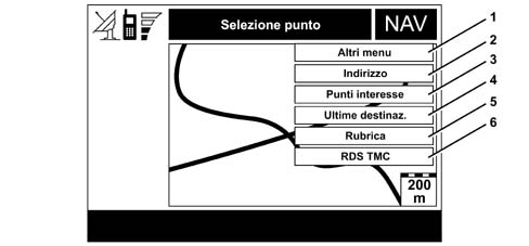
NAVIGATION SYSTEM MENUThe system includes three menu pages. These are shown on the display after selecting the navigation function page with key T20 "NAV" (see Fig.2), pressing knob (R2) (see Fig. 2) and selecting the item "Other menus" present on each menu page.The first page essentially contains functions that allow the destination to be set.Input of a destination by the user activates Route Calculation. The final outcome of the process is the identification of a chain of segments (route) that connect current vehicle position with vehicle destination.It is possible to select several destinations that are managed in sequence as they are reached.When a route is selected, the system generates all the information required to guide the user to the destination.It computes effective distance to the destination and keeps it constantly updated; it explores the route ahead of the car to find the first cross-roads (intersection of at least 3 roads) where the user must make a Turn (i.e. follow a road that is not the natural continuation of the current road) and identifies the Manoeuvre (e.g. left turn) that the user must make; lastly, it computes the distance to the turn-off and updates the distance.The system must take into account any deviations and check the vehicle is still on the correct route. If necessary it must carry out a Route Recalculation.If the vehicle leaves from an unmapped point, i.e. the vehicle is not localised on a segment, route calculation will begin only when the vehicle is identified on a map segment.The user may ask to calculate an alternative route to overcome local traffic problems, selecting the required distance within which the vehicle should return to the original route.If an alternative route is found, the user will be asked to accept the proposed deviation.When the system is turned off, the calculated route, set destination and navigation settings are saved in a flash memory.These will be available at the next key-on regardless of whether the Database Management type is Full or Reduced.If Database Management is Reduced, the information will be available to the user only after reinserting the Navigation CD because the map Database is not saved.Functions accessible from the first menu page are as indicated in the following figure.
1 - Other menus
2 - Address
3 - Points of interest
4 - Ultimate destinations
5 - Address book
6 - RDS TMC.
1. ADDRESS - TARGET DESTINATION INPUTTo enter a destination, select the "Address" function from the first menu page and display the submenu with the items "Town", "Street", "House number", "Address 2", "Map" and "OK". The menu fields always contain data on the last calculated route.2. POINTS OF INTEREST - USEFUL SERVICES IN FILEThis function provides access to a file with information and location of useful destinations of general interest, such as restaurants, museums, stations etc., divided according to category.Select "Points of interest" on the first page of the navigation menu to gain access to a submenu with the following selection criteria relating to the service sought:
Near vehicle
Near destination
Near address
Name.
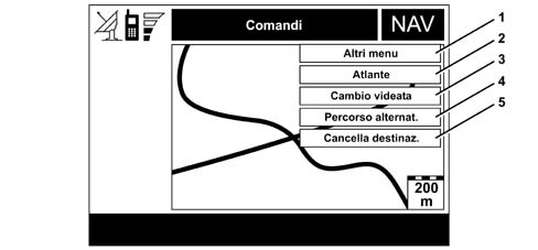
The procedure for entering selected service descriptions (category, town, street, house number) is the same as for the "Address" function.3. LAST DESTINATIONSSelect "last destinations" from the first page of the navigaion function menu to gain access to a list of the last 10 destinations entered. Set and confirm a destination to gain access to a map where the destination is represented by a cursor in the shape of a white cross.See "Map" in the paragraph on "Address - Entering target destination" for a description of the options available with this new screen.4. ADDRESS BOOK - DESTINATION ADDRESS BOOKSelect the function "Address book" on the first page of the navigation menu using knob (R2) (see Fig. 2) to gain access to a page containing characters for entering the Name of the selected destination. Proceed as described for the "Address" to enter the name: select "List" to gain direct access to a list of filed destinations (e.g. "Home").Confirm a destination to gain access to a screen that shows other stored information and the functions "Destination", "Modify", "Delete" and "Map".See the previous paragraph "Address - Entering a target destination" for information on the use of these functions and their corresponding submenus.5. RDS TMC - PUBLIC SERVICE INFORMATIONSelect the function "RDS TMC" on the first page of the navigation menu and confirm with knob (R2) (see fig. 2) to gain access to the functions "Near vehicle" and "Near address". These allow you to identify a geographical point about which you require RDS TMC information of general interest (e.g. accidents, queues, slow-moving traffic, fog etc.).RDS TMC information may be represented by symbols that appear on the map or a list of events. The navigation system is able to manage RDS TMC messages and also provide locations.To gain access to the next page, select and confirm "Other menus" using the knob.The following functions are accessible from the second menu page:
1 - Other menus
2 - Atlas
3 - Change screen
4 - Alternative route
5 - Cancel destination
2. ATLAS - ENTER DESTINATION ON MAPSelect the Atlas function on the second page of the navigation menu to enter a destination directly on the map. The display shows a map and a cursor in the form of a white cross that represents the destination.The map is always shown with North at the top of the display and with a 100 metre scale.The right side of the display shows the options " < > " (horizontal displacement) and "^ v" (vertical displacement, "Scale" and "OK".Use the displacement functions to move the cursor directly over the map to move the destination.Use the "Scale" function to alter the geographical map scale. The following scales are available: 100 metres, 200 m, 500 m, 1 km, 2 km, 5 km, 10 km, 20 km, 50 km, 100 km, 200 km.3. CHANGING SCREEN - INFORMATION ON DISPLAYSelect the function "Change screen" on the second page of the navigation menu to set the various information items shown on the display.The following options are available:
3.1 Map
3.2 Whole route
3.3 GPS info
3.4 Route info
3.5 Motorway info.
3.1 "Map"Select this option to display a map with the next two turn-offs shown on the left side.3.2 "Whole route"This option can be selected only after the system has calculated the route. It shows the entire route from the vehicle's current position and the destination.3.3 "GPS" informationWith this function active, the display shows the car's current position (longitude, latitude, altitude) and the number of receiving GPS satellites. The vehicle is shown graphically by a symbol inside cardinal points.3.4 "Route info"This option can be selected only after the system has calculated the route. It shows a list with current destinations (up to 8).3.5 "Motorway info"This function can only be activated during motorway routes. It provides information on the next two exits (name and distance from current position) and service areas (distance from current position).4. ALTERNATIVE ROUTEThe user can select the "Alternative route" function on the second page of the navigation menu to ask the system to identify a new route if possible (i.e. not the original calculated route) to the destination.Calculation of the new route begins from the current car position and ends at a distance set by the user. Once a new route has been calculated, the display shows route differences and estimated time to reach the destination. The user is asked to confirm (YES/NO) whether or not to adopt the new route.Following confirmation, the navigation system replaces the current route with the alternative route. If the new route is cancelled, the system returns to the original route.If an alternative route cannot be identified, the display shows a notification message.5. CANCEL DESTINATIONSThis function is on the second page of the navigation menu and can be used to delete the selected destination from the memory.To gain access to the next page, select and confirm "Other menus" using the encoder (R2) (see Fig. 2).Use the third page to set certain route parameters (calculation, preferences) and map display modes (where possible).
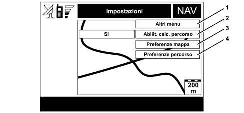
The following functions are accessible from the third menu page:
1 - Other menus
2 - Enable route calculation
3 - Map preferences
4 - Route preferences.
2. ENABLE ROUTE CALCULATIONUse the "Enable route calculation" option accessible from the third navigation menu page to enable or disable (YES/NO) road guidance. Voice announcement and display of the sequence of manoeuvres to be carried out and calculation of distances to subsequent manoeuvres can be activated/deactivated while keeping track of vehicle position and the recommended route.The Route Calculation option includes the following actions:
Calculating route between current position and destination.
Recalculating the route in case of deviation from the current route.
Calculating an alternative route.
3. MAP PREFERENCESSelect this function from the third navivation menu page to gain access to a new page with the following submenu:
3.1 Map design
3.2 Zoom in on crossroads
3.3 Icon design
3.4 Wording design
3.5 RDS-RMC design
3.6 Area design
3.7 OK
3.1 Map designUse this function to select map orientation on the display.The following options are available:
Orientation to north
Automatic orientation.
Vehicle position on the map is not updated in real time but after the car has moved through a certain distance or has changed direction and turned through at least 5 degrees.When the first option is selected, the map is shown oriented to the north and the vehicle icon is oriented accordingly.When the automatic orientation setting is selected, the navigation system automatically displays the map oriented in the direction of the vehicle when low scale values are selected (from 100 m to 2 km) and oriented to the north with high scale values (from 5 km to 200 km).3.2 Zoom in on crossroadsUse this option to enable or disable (YES/NO) the map enlargement function when the vehicle approaches a crossroads.3.3 Icon designUse this option to deactivate or activate representation of selected points of interest (e.g. hotels, service stations, restaurants etc.) on the map by means of icons.To deactivate the icon representation, select and confirm "NO". To activate, select and confirm relevant services on the list.3.4 Wording designUse this option to enable or disable (YES/NO) the appearance of town names on the map. The names displayed depend on the active scale:
100/200 Km, only capitals, cities and large towns
50 Km, also medium-sized towns
5/10/20 Km, also small towns
2 Km, any town
500m/1Km, also villages
100m/200m town districts
3.5 Tds Tmc designUse this option to deactivate or activate the representation of RDS TMC event categories ("NO","Traffico", "Meteo", "Info") on the map using icons.To deactivate the icon representation, select and confirm "NO". To activate, select and confirm one of the categories on the list. Only one event category at a time can be represented on the map.3.6 AREA DESIGNSelect this function to accesss the following map representation options:
NO (representation with segments of roads, rivers etc.)
2D (representation with coloured segments and blocks
3D (three-dimensional representation).
4. ROUTE PREFERENCESSelect this function from the third page of the navigation memory to gain access to a new page that can be used to enter user route calculation preferences. The navigation system automatically offers only options that can really be activated.The following functons are available:
4.1 Route type
4.2 Motorway
4,3 OK
4.1 Route typeUse this function to select one of the main route calculation criteria, i.e. "Less time" or "Less distance".In the first case, the navigation system chooses a route that mainly uses motorways and main roads. If the second option is selected, the shortest route is identified.4.2 MotorwayUse this option to establish whether the navigation system should or should not include (YES/NO) motorway routes when calculating the route.4.3 OKTo activate the new settings, select and confirm "OK" with the knob. Press the "ESC" key (see Fig. 2) to return to the previous screen and maintain the original settings.To return to the first menu page, select and confirm "Other menus" using the knob. Press the knob to make the menu disappear from the display.
TRIP function
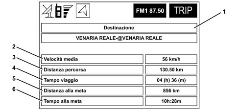
TRIP menu information refers to the route entered in the NAVIGATION functionCalculations to determine values to be displayed are activated when a destination is entered.Calculations are deactivated when the destination is reached or cancelled.Route deviations (automatic recalculation) do not lead to a calculation reset.The data are recorded in the memory when the system is turned off.The following figure shows an example of a screen that is displayed when the Trip button (see Fig. 2) is selected on the front panel.
1 - Destination
2 - Average speed
3 - Distance travelled
4 - Journey time
5 - Distance to destination
6 - Time to destination
1. Destination
Indicates destination set.
2. Average speed
Indicates average vehicle speed expressed in "Km/h" or "Miles/h" according to the "Distance Measurement" option selected in the Set_up menu.
3. Distance travelled
Indicates distance travelled by vehicle expressed in "Km" or "Miles" according to the "Distance Measurement" option selected in the Set_up menu.
4. Journey time
Indicates time elapsed expressed in hours and minutes.
5. Distance to destination
Indicates distance between current vehicle position and the set destination expressed in "Km" or "Miles" according to the "Distance Measurement" option selected in the Set_up menu.
6. Time to destination
Indicates the estimated time to reach the set destination expressed in hours and minutes.
Telephone function
General remarks
The Connect system is equipped with a Dual Band GSM mobile phone with handsfree operation.Display mobile phone funtions by means of a short press on the TEL key (see "Fig. 2) or key T1 (see Fig. 2).The phone module can be used for normal phone calls, text messages and data transfer.To deactivate the phone, keep the TEL key (see Fig. 2) pressed down. Press the TEL key or key T1 (see Fig. 2) briefly to reactivate.This phone module comes with a handsfree device that allows the user to hold a conversation without using a receiver.The phone module also makes use of the Connect Voice Recognition function to allow the user to activate certain phone functions (more details are given in the relevant paragraph).The mobile phone offers the following useful functions:
PIN (Personal Identification Number) to prevent unauthorised use of the phone
change PIN
activate/deactivate PIN request for access
accept or reject incoming calls
send a phone call
emergency call (even without a SIM card and without entering the PIN code)
read phone numbers saved on the SIM card
enter a new phone number on the SIM card
delete a phone number from the SIM card
information on SIM card status (correct or incorrect input and space available in memory)
access to a list of the last 10 numbers dialled to facilitate use of recurrent calls
access to a list of the last 10 calls received
text message management to receive and send a short text message
activate and deactivate access to the SIM (Subscriber Identification Module) phone card
access and modify lists with most frequently dialed numbers and phone list;
manual diallling
DTMF (Dual Tone Multi Frequency) settings to allow repeat dialling
prohibit transmission of personal identification number
select network access provider
set incoming call volume and sound
display remaining credit in the case of prepaid SIM cards
display signal field intensity and other status reports
Main menu functions
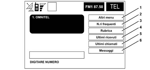
The main mobile phone functions, accessible by a short press on the TEL key or phone key, are shown in the main function screen in the figure below:
1 - Other menus (access to the second menu page)
2 - Frequent numbers (list of the 9 most frequently used numbers)
3 - Address book (address book with names and phone numbers)
4 - Last calls received (list of the last 10 calls received)
5 - Last calls made (list of the last 10 numbers called)
6 - Messages (SMSs - short text messages)
1. Other MenusSelect and confirm "Other menus" to gain access to the second phone function screen. Functions are as follows:
Information (information on network operator and SIM card).
Transfer from the first to the second phone menu page and viceversa takes place cyclically by selecting and confirming "Other menus" on each page.2. "Frequent number" functionUse the "Frequent number" function to generate and gain fast access to a list of 9 most frequently called numbers. The system can automatically manage and recognise the "frequent number" lists of up to 5 different SIM cards.3. "Address book" functionUse this function to save (in alphanumerical or voice form) phone numbers and references (name, number, location and voice recognition)Enter a new item in the phone book by selecting the "Address book" function on the main phone function page.Use the function to decide whether to save the phone numbers on the SIM card or in the system phone book.The "Voice recognition" function is available only if the new item has been saved in the system phone book. In this case, the message "Enabled" is displayed. If the item is transferred from the system address book to the SIM card, the system notifies the user that the voice sample is to be deleted.4. "Last calls received" functionSelect this function to gain access to a list of the last 10 calls received. Each item on the list includes the name of the caller (if saved in the address book and if the call was not made incognito) and the phone number. To call one of the items on the list directly, simply select and confirm using the knob.5. "Last calls made" functionSelect this function to gain access to a list of the last 10 calls made. Each item on the list includes the name of the call recipient (if saved in the address book) and their phone number. To call one of the items on the list directly, simply select and confirm using the knob.6. "Message" functionUse this function to access the incoming and outgoing text message (SMS) page. A menu is displayed with the following options:
Create (to write a message)
Select (to select a message)
Serv. Centre No. (service centre number for messages).
Voice commands
The user can use the "Voice Recognition" function to order Connect to carry out certain phone functions by voice.Voice recognition may take place in two ways:
without voice identification (Speaker Independent mode).
with voice identification (Speaker Dependent mode).
In the first case, the system can receive a voice command regardless of the user's tone of voice and sex.In the second case, the system can identify a voice sample by comparing a vocal utterance with a corresponding utterance saved previously by the same user. This type of voice recognition is applied to the phone function in this case.Voice commands take precedence over contols on the system control panel and on the steering wheel (if present).For a full description of Voice Recognition, refer also to the specific function description.
Fleet management function
This function is a brand new feature for the Connect system.The user can send its position and additional information to a certain phone number by means of a text message.This option allows users to manage their own vehicle fleet independently. Connect provides real-time information on vehicle position.This option is available only for Connect versions with a GSM phone.The fleet management function is suspended if the modem interface is active, because the GSM phone cannot be used simultaneously to send text messages and as a modem.
Operating procedure
When active, the "Fleet Management" service sends a text message [posizione + city name + street name + time + vehicle identification] to the fleet control centre phone number in accordance with a cyclic sequence set by the user using the GSM phone in Connect."Fleet management" service data are activated and entered by means of the "Fleet Setup" menu that can be activated from the "MAIN" page.When a navigation CD is present, vehicle position is further processed by map matching to ensure correspondence with map co-ordinates in Connect.Absence of the navigation CD does affect system operation.The time transmitted is the time recorded by GPS.The Connect system synchronises with the GPS time, when the GPS is visible to reconstruct a time base that can be used to define messages to be sent to the control centre.The navigation system does not possess its own internal clock and cannot obtain time information from any other vehicle devices because the vehicle is not fitted with a telematic network.
Operating requirements
"Fleet management" function operation is dependent on the following conditions:
The outgoing text message is in the following format: [position + city name + street name + time + vehicle identification]"Position" is expressed by indicating latitude and longitude."City name" and "Street name" fields can be completed only with the navigation CD inserted.Time is expressed in the following format: seconds;minutes;hours;day;date;'month;year.The vehicle identification is the vehicle registration number.Each field ends with the character '#'.Each subfield ends with the character ;'.The Latitude value is preceded by LT:.The Longitude value is preceded by LG:.
What happens when a message cannot be sent
A text message cannot be sent if one of the following conditions arises at the time of transmission:
Connect off
SIM removed or not enabled
GSM signal inadequate
In this case, the system saves the last vehicle positions (up to a maximum of ten).When normal service conditions are restored, the system sends inevitably delayed text messages containing saved positions.If Connect is off (vehicle location not possible), the saved messages will contain an incorrect vehicle location (e.g. the first recorded upon reactivation).
Fleet management menu
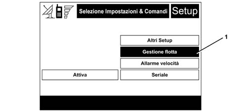
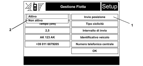
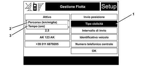
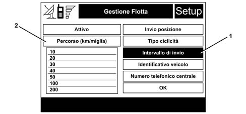
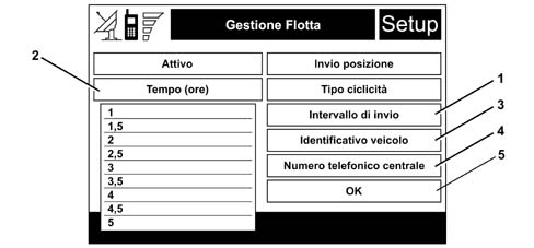
The function is managed from a special dedicated page that can be called up using a key in the Main %rarr Set_up menu.Press the right encoder R2 (see Fig.2) to display the possible options, turn the encoder R2 (see Fig.2) to highlight Set_up (1).The second screen on the Set up menu will be highlighted.Turn the encoder R2 (see Fig.2) to highlight "Fleet management" (1) and select the item.The "Fleet management" screen will be displayed to enable data and options to be entered.To select position transmission type, turn the encoder to highlight the "Send position" item (1).When an item is selected, a drop-down menu (2) will appear showing "ACTIVE/INACTIVE" optionsTurn the encoder R2 (see Fig.2) and press to select.To select cyclic sequence type, turn the encoder R2 (see Fig.2) to highlight the "Cyclic sequence" item (1).Press to open a drop-down menu containing the items "Distance travelled (Km/Miles) (2) and Time (hours) (3).Selec distance travelled (Km/Miles) to send the information according to the km distance interval specified in the "transmission interval" field.Select "Time" to send the information at the end of each time interval specified in the "transmission interval" field (e.g. 1.5 = 1 hour and thirty minutes).Turn the encoder R2 (see Fig.2) and press to select the required item.Enter the transmission cycle frequency by turning the encoder R2 (see Fig.2) to select "Transmission interval" (1). Select the item to open a drop-down menu.If the option "Distance travelled (Km/Mile)" (2) is selected under "Cycle type", a drop-down menu appears with several distance intervals (in km or miles)Press the encoder R2 (see Fig.2) to select the required value.the option "Time (h)" (2) is selected under "Cycle type", a drop-down menu appears with several time intervals (in hours) appears under "Transmission interval" (1).Press the encoder R2 (see Fig.2) to select the required value.To enter the vehicle identification data (e.g. registration number), turn the encoder to highlight "Vehicle identification" (3) and press to select the item.Press ESC to cancel.Open the page to enter the alphanumerical strings.Turn the encoder to select the required character in sequence and press to select.Press ESC to return to the previous screen.At the end, select "OK" and pressThe system will return to the "Fleet Management" screen and the "Vehicle identification" field will display the input stringTo enter the exchange phone number, turn the encoder R2 (see Fig.2) to select "Exchange Telephone Number" (4) and press.Press ESC to cancel.Open the page to enter the alphanumerical strings (see above)Turn the encoder R2 (see Fig.2) to select the required numbers in sequence and press to select.Press ESC to return to the previous screen.At the end, select "OK" (5) and press to select.The system will return to the "Fleet Management" screen.The "Exchange Phone Number" field will display the input string.If "Send position" is ACTIVE and if all the subsequent fields have been completed, the OK key is active.Turn the encoder R2 (see Fig.2) to select and press to confirm data.Press to confirm the input data and return to the screenPress ESC to return to the previous screens.
TARGAsys Services
The manufacturer provides the user with an optional package with the name of TARGAsys.TARGAsys is managed by the manufacturer's operations centre. It makes available information and services designed to aid the vehicle and user when in the area.TARGAsys are not supplied together with the Connect system but constitute an option that can be purchased by the user.Press Connect key (1) to access TARGAsys services.If the user selects a TARGAsys service, the Connect system communicates the request to the operations centre. The operations centre processes the required information and sends it to the user.The Connect system communicates with the TARGAsys via text messages (using the TELEPHONE function), while an operator at the TARGAsys centre responds to the user by voice. Information requested by the user is also supplied by the operator in the form of text messages.
Assistance function
Assistance menu
The ASSISTANCE menu is a hidden menu, i.e not immediately accessible to the user. To display the ASSISTANCE menu, follow the operation sequence described below:
display the MAIN page
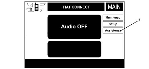
press the encoder on the right R2 (see Fig.2)to display the "Store item, Setup" Soft_buttons
give T18 "Audio off" (see Fig. 2) a long press until a message appears on the screen
press keys 1, 2, 3 on the number keypad (see Fig. 2) in sequence
press the right encoder R2 (see Fig.2)again: the "Assistance" option (1) will appear.
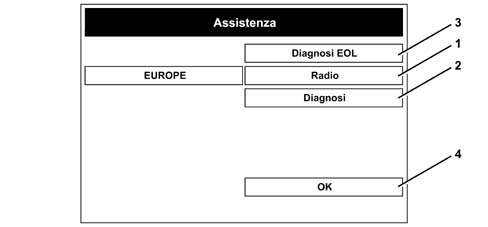
Turn the right encoder R2 (see Fig.2) to highlight assistance and press: the second page of the assistance menu will be displayed:
1 - Radio
2 - Diagnostics
3 - EOL Diagnostics
4 - OK
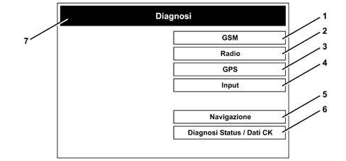
1. RADIOSelect "Radio" to display a drop-down menu that can be used to select the Radio application area: the radio receiver automatically adapts to the broadcast specifications of the selected area.2. FAULT DIAGNOSISSelect the "Diagnostics" item to highlight the screen shown in the following figure, containing the following submenus:
2.1 GSM
2.2 Radio
2.3 GPS
2.4 Input
2.5 Navigation
2.6 Status/ CK Data diagnostics
1 - GSM
2 - Radio
3 - GPS
4 - Input
5 - Navigation
6 - Status/ CK Data diagnostics
7 - Diagnostics
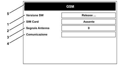
2.1 GSM: turn the encoder R2 (see Fig.2) to select GSM, when the screen shown in the following figure will appear
1 - SW version: Indicates the identification number of the SW code that controls the GSM module
2 - SIM Card: Indicates whether the SIM card is Present/Absent in the SIM Card reader
3 - Aerial signal: Indicates GSM field intensity expressed in values from 0 to 99
4 - Communication: Indicates connection status with the GSM module: Green OK, Red KO
5 - GSM
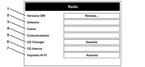
2.2 RADIO: turn the encoder R2 (see Fig.2) to select RADIO, when the screen shown in the following figure will appear
1 - SW version: indicates SW version of the radio module
2 - Aerial: indicates connection status of the AM/FM aerial: Green field OK/Red field KO
3 - Speakers: indicates speaker connection status: Green field/ OK Red field KO
4 - Communication: Indicates connection status with the radio module: Green field/ OK Red field KO
5 - CD - Changer: Indicates whether the device is connected
6 - internal CD: Indicates communication status with CD player: Green field OK /Red field KO
7 - HI FI system: Indicates whether an amplification system (final) has been connected.
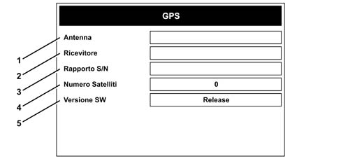
2.3 GPS: turn the encoder R2 (see Fig.2) to select GPS, when the screen shown in the following figure will appear
1 - Aerial: indicates connection status with GPS aerial; Green OK, Red KO
2 - Receiver: Indicates connection status with GPS receiver; Green OK, Red KO
3 - S/N ratio: Indicates signal/noise ratio: Green OK, Red KO
4 - Satellite number: Indicates number of satellites visible: Background colour (green, yellow, red) provides a visual indication of signal quality.
5 - SW version: Indicates the identification number of the SW code that controls the GPS module.
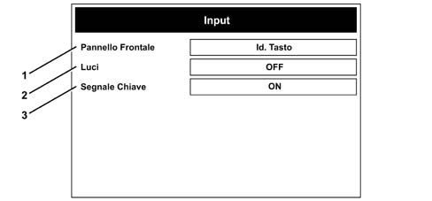
2.4 INPUT: turn the encoder R2 (see Fig.2) to select INPUT, when the screen shown in the following figure will appear
1 - Front Panel: used to check operation of each key, showing an identification string when the key is pressed.
2 - Lights: used to check whether the Lights On/Off signal is correctly recorded by Connect.
3 - Key signal: used to check whether the +15 signal is correctly received.
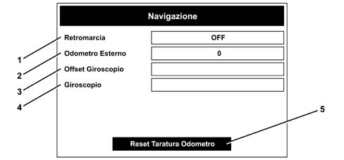
2.5 NAVIGATION: turn the encoder R2 (see Fig.2) to select NAVIGATION, when the screen shown in the following figure will appear.
1 - Reverse: used to check whether reverse is engaged or not (On/Off)
2 - External Odometer: indicates number of pulses received from speed sensor. The field is blank
3 - Gyroscope Offset: indicates whether Gyroscope Offset has been correctly evaluated: Green field OK /Red field KO
4 - Gyroscope: indicates whether the signal from the gyroscope is within the valid range: Green field OK /Red field KO
5 - Odometer Reset
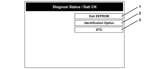
Select the "Odometer Reset" option to display a dialogue window that asks the user for confirmation before continuing with the reset procedure: select OK to start the reset procedure. Select ESC to exit the screen.2.6 STATUS /CK DATA DIAGNOSTICS: this item allows access to other diagnostic submenus. Select the "Status /CD Data Diagnostics" item to highlight the screen shown in the following figure, containing the following submenus:
2.6.1 EEPROM data
2.6.2 Identification Option
2.6.3 DTC
1 - EEPROM Data
2 - Identification Option
3 - DTC
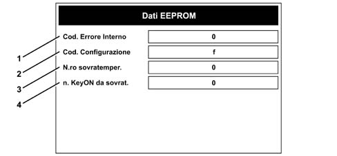
2.6.1 EEPROM data: Select the option "EEPROM Data" to display the page shown in the following figure.
1 - Internal Error code: the HEX value indicates the active internal error identification code
2 - Cod. Configuration: the HEX value, converted into binary code indicates system configuration status.
3 - Tempeature surge number: indicates value of temperature surge counter in diagnostic SW module.
4 - No. of Key-ONs since temp. surge: indicates number of key-ONs since last temperature surge event
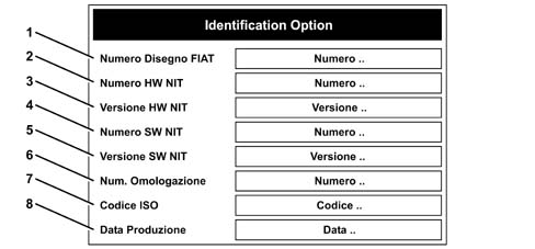
2.6.2 Identification Option: Turn the right encoder R2 (see Fig.2) to highlight the identification option and press: The page shown in the following figure will be displayed.
1 - FIAT part number: indicates the Part number used to identify the component in the plant
2 - Connect HW number: indicates HW code
3 - Connect HW version: indicates HW version
4 - Connect SW number: indicates SW code
5 - Connect SW version: indicates version of SW installed on device
6 - Homologation number: indicates the homologation number
7 - ISO code: indicates ISO code
8 - Production date: indicates production date
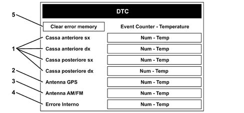
2.6.3 DTC: Turn the right encoder R2 (see Fig.2) to highlight DTC and press: The page shown in the following figure will be displayed.
1 - Speaker field: provides information on the status of each individual connected speaker:
2 - GPS aerial: provides information on the connection status of the GPS aerial
3 - AM/FM aerial: provides information on the connection status of the AM/FM aerial:
4 - Internal error: provides information on system internal error status:
The following information is displayed in order in each of the windows that appear beside the options listed above:
Number of problems arising (counter is initialised to 64, i.e. 64 indicates zero errors occurred, 60 indicates 4 errors occurred).
Temperature at which the last error occurred
Background colour: Red error present/Green error absent.
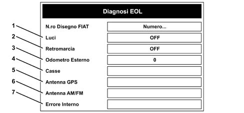
CLEAR ERROR MEMORY key (5): this key, always active with key-ON or otherwise blacked out, activates the error memory deletion process managed by the diagnostic SW module when pressed.For some error types, memory deletion and update take place only after the key-Off - key-On stage.After this stage, the error memory will only count errors actually present at that moment to facilitate diagnostics.Press ESC to cancel the operation and return to the DTC page.Carry out a Key-off and Key-on cycle to delete and update the error memory.Return to the DTC page after key-ON to display updated DTC status.3. EOL DIAGNOSTICSSelect EOL Diagnostics on the Assistance page. The "EOL Diagnostics" page shown in the following figure will be displayed.
1 - Lights: used to check whether the Lights On/Off signal is correctly recorded by Connect.
2 - Reverse: used to check whether reverse is engaged or not (On/Off).
3 - External Odometer: indicates number of pulses received from speed sensor. Green field indicates scale factor calibration optimal, red Field indicates scale factor calibration non-optimal.
4 - Speakers: indicates speaker connection status: Green field OK /Red field KO
5 - GPS aerial: indicates connection status of the GPS aerial: Green field OK/Red field KO
6 - AM/FM aerial: provides information on the connection status of the AM/FM aerial: Green field OK /Red field KO
7 - Internal error: provides information on system internal error status: Red error present/Green error absent.
Voice recognition function
The voice recognition function allows the user to interact with the Connect system by means of voice commands.Various functions (navigation system, radio/CD, phone) can be managed according to the Connect configuration.This function is designed to recognise the existence of words defined as "First Level" that enable a set of commands linked to a given environment. These commands remain available as long as the user pronounces another First Level word.The command imparted with the First Level word determines access to a set of subordinate 2nd, 3rd and 4th level commands.A set of service voice commands is also present that do not control a Connect function directly but are useful for managing user-system communication.
Operating Procedure
The Voice Recognition function operates in two ways:
Speaker Independent mode.
Speaker Dependent mode.
When in Speaker Independent mode, the Connect system analyses speech received from the microphone in accordance with a model independent of sex, tone of voice and user inflections. No training stage is required to interpret the commands.The user presses the appropriate button to request interpretation of a voice command. The Connect continues the conversation and Guides the User to provide information required to carry out the requested service.Speaker Dependent mode is available for voice interaction with the phone book and navigation system..The User may, for example, associated each phone number in the Connect address book with a voice sample. The User may then ask Connect to make a phone call through recognition of a previously-stored voice sample.In Speaker Dependent mode, Connect cannot be expected to recognise voice samples saved by a User other than the person speaking the commands.Voice recognition is designed to communicate with the user is different languages.
Voice Memo
The voice recognition function allows the recording of voice messages known as Voice Memos.The Voice Memo allows the user to record and play back a certain number of voice messages. The messages are recorded in sequence and the total space corresponds to 3 minutes (180 seconds).The user-activated recording can last up to 180 seconds (depending on the available space) and ends automatically when this time is up.The user can interrupt the recording manually in any case.The Voice Memo can play back voice messages from the last message recorded followed by previous messages. Once everything in the memory has been played, the first message is played again. The voice memo can skip to the previous or next message.The Voice Memo can clear the entire memory available for recording.
Address book
Connect contains two different address books: one for the phone and the other for the navigation system.The purpose of both is to make it easier to enter data (a phone number or destination) required by the user without going through a long procedure each time.This operation may be carried out once only and the result is saved in Connect and associated with a mnemonic. Then all you have to do is identify a saved option by selecting from a list or entering the mnemonic name.Both address books are also stored in a back up memory (flash memory). This means that information stored persists even after the system has been turned on and off or after the battery has been disconnected.PHONE BOOKThe following fields are present in the phone book:
name: mnemonic label for fast access to the list.
phone number: number used by Connect for calls.
origin: origin of item in phone book (Connect memory or SIM CARD).
Name and number may be entered by the user during creation of a new address book item. In this case, the origin field indicates that the item is stored permanently in the Connect internal address book.Or Name and Number may be present on the SIM Card that the user has entered in the Connect SIM Reader. The System also displays this information as phone book items. After the Card has been inserted, the address book management module reads all the items on the Card and makes a copy by creating new temporary items if the name/number pair is not already present in the Connect address book. In this case, the origin field indicates that the item comes from the SIM CARD.This item type is deleted from the address book when it is downloaded or the system is turned off.The following phone book functions are available to the user:
enter new item
delete existing item
select item for phone call
modify name field or number field for an individual item.
All items on the SIM Card can also be copied permanently into the Connect address book (the origin field will thus be modified).NAVIGATION ADDRESS BOOKThe following fields are present in the navigation phone book:
name: mnemonic label for fast access to the list.
description of geographical location defined by user: string consisting of town name/street name or name of associated POI...
co-ordinates: place co-ordinates (not made available to user and used internally for localisation or route calculation).
The user may enter the name during creation of a new address book item while description and co-ordinates are selected by accessing the map database.The following phone book functions are available to the user:
enter new item
delete existing item
selecting (via name) item for route calculation/vehicle localisation
modification of individual item name field.
TV camera function
General Description
The Level 4 configuration of Connect is designed to:
receive and display a composite signal from the parking TV camera.
Display Mirroring effect images on the TFT display (as though the image object were viewed in a mirror) when reverse engaged.
Automatically detect the presence of the TV camera to activate the function.
Keys
All keys on the front panel are disabled, with the exception of (see "Control description" paragraph):
MAIN for stand-by management
Connect /SRC / T2 (see Fig. 2)
Rotating encoder R2 (see Fig. 2) for brightness adjustment
Rotating encoder R1 (see Fig. 2) for volume adjustment
CD Eject / ESC (see Fig.2)
Image Brightness Adjustment
TV camera image brightnes is adjusted by turning the encoder.Any Image brightness adjustment level is maintained even after subsequent reverse disengagements and engagements.At each new key-ON, the brightness is returned to a default level between min and max.
Priority
The TV camera image is displayed only with Connect on and reverse engaged.TV camera image display is enabled only at the end of Voice Recognition sessions. Voice Synthesis, access to Navigation data on the navigation disc or access to data on the navigation disc must be terminated.If the navigation system is in use, reverse engagement inhibits access to data on the disc.When the TV camera is activated, the other Connect functions stay on the background, i.e. they are no longer displayed but a subset of functions remains operational.ASSISTANCE MODEWhen the system is in ASSISTANCE mode, reverse engagement does not display the TV camera image so that the reversing signal can be checked.WARNINGAll the Warning Boxes are disabled.If required by modules active in the background, these are saved in time order and displayed upon TV camera deactivation: warning box "n" stays on the screen until ESC is pressed. Warning box "n+1" is displayed when ESC is pressed.The Warning Box queue does not include TEL module screens (e.g. incoming Tel, number.... no).MAINThe MAIN key is DISABLED except in the following circumstances:
With DARK active, reverse engagement DOES NOT DISPLAY THE TV CAMERA IMAGE.
With Dark active and reverse engaged (i.e. TV camera image not displayed), the TV camera view is activated when Dark is excluded by pressing the MAIN key. When the TV camer is turned off, the MAIN page is displayed.
With Dark active and reverse engaged (i.e. TV camera image not displayed), the corresponding active Connect function page is displayed when Dark is excluded by pressing the Connect key.
When the TV camera image is displayed, it is not possible to transfer to Dark because the MAIN key is disabled.
When the TV camera image is displayed, it is not possible: to activate Voice Memo (because this function is contained in the MAIN application, unless the dedicated key is activated), to activate the Setup function
AUDIO FUNCTIONThe AUDIO application is operational.Audio hard key is disabled.Enter key (right encoder depression) is disabled so that depression of enter does not active the relevant options if the TV camera is activated when the audio page is displayed.Any sound source that is active (Audio CD, Radio) remains active.Volume may be adjusted by means of the left encoder.The Audio CD may be removed.The SRC key is operational.The SEEK keys are not operational.PHONE FUNCTIONThe TEL application is operational.TEL hard key is disabled.Phone keypad hard keys are disabled.An incoming call event determines:
TV camera image disablement.
Managed as for phone application in incoming phone call mode
Depression of the Phone Handset key determines:
TV camera image disablement
Display of last number dialled as per phone specifications
A further press on the phone handset key sends the call within 10 s and switches back to the TV camera viewIf the handset is not pressed again within 10 s, the TV Image is restored and the first press is overlookedA call can only be sent to a number other than the last dialled call via VR. At the end of the phone call, the TV camera image is reactivated if reverse is still engaged.NAVIGATION FUNCTIONThe NAVIGATION application does not access any navigation CD data that may be present.The NAVIGATION application does not impart voice commands.The NAV CD extraction command determines:
Suspension of TV camera image display
Presentation of warning box: "TV camera display will be reactivated at the end of the CD extraction stage". Duration 3 s.
A yes/no answer to the request to navigate without a CD determines TV camera image restoration only when access to CD data is complete.
If reverse is disengaged, the system displays the navigation page.TARGAsys SERVICESConnect key depression deactivates TV camera image display and displays the corresponding page.The system displays the warning box: "TV camera display will be reactivated at the end of the Service session". Duration 3sIf the services are not active, a "Services no active.... " warning box will be displayed. Press ESC to delete the warning box and reactivate the TV camera if reverse is still engaged.If reverse is no longer engaged, the service page is displayed.VOICE RECOGNITION FUNCTIONVoice command activation determines suspension of the TV camera image display.
Connect - TV camera interface
TV CAMERA INPUTThe interface is an NTSC (National Television Standard Comittee)-format composite video type.Two pins of the MQS connector are dedicated to this interface. These are connected to the video signal and reference (cable and shield).TV CAMERA POWER SUPPLYConnect supplies a dedicated power source to the TV camera. The power stage is software-managed so that it can be enabled or disabled as required.
TV camera menu
No dedicated TV camera management menu is present.
Data Interface Function
Connect is designed to manage a DCE-type external hardware device (e.g. Computer, printer, ...)The configuration normally used for computers, terminals, printers etc. is defined a DTE (Data Terminal Equipment) configuration.The configuration normally used for modems is defined a DCE (Data Communications Equipment) configuration.These different configurations define the type of signal that each device expects at each pin.Any device may be configured as a DTE or DCE.Connect acts as a DCE, the external device (typically a computer) acts as a DTEA lead with a direct pin-to-pin connection is used as a connection device for this configuration.Maximum transmission speed is as specified for the GSM Phone module, i.e. 9.6 kbps.A serial line consisting of a lead with a direct pin-to-pin connection is used to connect the Connect system to the external device.No dedicated connector is required. The pin-out is described in the paragraph on the pin-out.
Priority.
The serial interface used allows the system to detect data transmission/reception on the channel and thus establish access priority levels to the GSM transmission module.Data interface priorities for Connect functions are described below.TARGAsys SERVICESEmergency calls (in automatic mode) and/or Connect key depression suspend all activities in progress on the serial line to make the GSM module available for the selected purpose.The following message is displayed: Serial Connection Interrupted.All data exchanged during the interrupted communication session on the serial line are lost.At the end of the emergency call or activated service, the previously active communication session on the serial line is not automatically resumed.PHONE FUNCTIONWhen the Data Interface function is active, the following conditions are determined:
Phone menu locked
Input caller block
Outgoing caller block
The data interface cannot be activated when a phone call is in progress.NAVIGATION FUNCTIONWhen the Data Interface function is active, the Navigation Function can be activated. Serial line data transmission may be slower if the Navivation function is active.RADIO / CD / MP3 PLAYER FUNCTIONSThese functions are independent of the Data Interface function.
Actiation, deactivation and use of the Data Interface
The DEFAULT status upon activation of Connect with key-ON or key-OFF is: Data communication on RS 232 line INACTIVE.After engine shut-down, the Connect system remains active for 20 minutes unless the left encoder is pressed (immediate shut-down) or the GSM communication carries on.If the GSM communication carries on to the end of the 20 minute period, a second 20 minute period will automatically start.ACTIVATION/DEACIVATION PROCEDURESelect the MAIN menu and press the encoder to display the options (See "Fleet management" paragraph).Select Setup (See "Fleet management" paragraph).The field to the left of the "Serial" option (1) indicates current status:
Serial "Inactive" = serial communication not possible
Serial "Active" = serial communication operational
To change status (from "Active" to "Inactive" and back), select "Serial". Status changes automatically.If GSM field intensity is insufficient or the SIM card is not inserted or invalid, the "Serial" item cannot be selected.Status cannot be changed and therefore remains "Inactive".In this case, no communication session can be opened with data transmission/reception via the serial line.
1 - Serial
FAILURE TO DEACTIVATE SERIAL COMMUNICATIONIf the option "Serial = Inactive" option is not selected at the end of data Transmission/Reception via computer, the procedures described in the Priority paragraph continue to apply.In particular, if an attempt is made to access the Telephone menu or if the key is pressed to call the last number dialled, the following message will appear: SERIAL COMMUNICATION ACTIVE: TELEPHONE NOT AVAILABLE.SETTING COMPUTER TO BE INTERFACEDThe computer interfaced with the Connect system must have:
serial port set for a transmission speed of 9600 bps.
A modem installed.
If the modem is correctly installed, all applications that require a telematic link with external databases/servers may be used.
Speed alarm function
Operating principle
The Speed Alarm function issues an acoustic alarm and a visual alarm when vehicle speed exceeds a preset threshold "Vlim" (Speed limit).The speed alarm and acoustic alarm function can be activated/deactivated from a dedicated menu.The acoustic alarm takes the form of a set of tones.The visual alarm takes the form of a screen message (1) "Attention: speed limit exceeded" that is displayed for 3s after the threshold has been exceeded. This visual alarm takes priority over every other display.The alarm contains symbol (2) containing the set value.Exceeding of Vlim triggers the acoustic and visual signals.The acoustic signal remains active for a time established by the acoustic signal screen and the screen signal remains active for up to 3 s.The signals are deactivated for V < Vlim-5 regardless of time elapsedThe user enters a numerical speed limit value by turning the encoder. The numbers change in steps = 5. Speed range [30-250]km/h, or [20-155] mphThe measurement unit applied to input numbers is as specified in the Setup menu in the "Distance Measurement" field (km or Miles).If the speed alarm is deactivated (Alarm = inactive) and the speed limit is changed (e.g. from 130 to 190), it will activate automatically.When the measurement units are changed from km to miles and viceversa, the number representing the speed threshold (Limit key) remains valid but takes the new measurement unit into account.The set values are active only after confirming with the "OK" key..
Settings
Display the MAIN page and press the right encoder to display the items "Store item" and "Setup", Then select "Setup".Select the option "Speed alarm" (1) on the "Setting and Control Selection" page.
1 - Speed alarm
Access the "Speed alarm" pageTo change alarm status from Activated to Deactivated, select the Alarm option (1) and press the right encoder.To enter a speed limit, select the option "Limit" (2), press the right encoder and turn to alter the figure displayed.To Activate or Deactivate the acoustic alarm (Buzzer), select the option "Buzzer" (3) and press the right encoder. Status will change automatically.At the end, highlight OK and pres the right encoder to confirm the settings.