Descriptions
INSTRUMENT PANEL
Engines: 2.0 16V, 2.0 JTD 8V, 2.3 JTD 16V, 2.8 JTD 8V
DESCRIPTION OF THE SYSTEM
Instrument panel control unit operation
The role of the control panel, produced by Magneti Marelli, is to display vehicle operating parameters and to notify the driver of any possible faults in the on-board electronic systems.The main functions performed by the instrument panel are listed below:- electronic speedometer and speedometer repeaters on the basic version with a speedomeer output. optional versions with four speedometer outputs with three active and one spare
- mileometer/trip counter
- electronic rev counter
- engine coolant temperature gauge with overheating warning light;
- fuel level gauge with reserve warning light and signal repetition unit;
- various warning lights (fault, activation etc.);
- panel lighting, graphics and pointers, with LEDs;
- LED mileometer lighting even during daylight;
- panel lighting and fixed graphics with lights on
- automatic transmission failure and speed engaged warning light for vehicles with automatic transmission
- clock function with hour and minute regulation
- engine oil level (only for optional versions)
- services.
Composition
From a design point of view the panel consists of the following components:- two multifunction buttons for the milometer, servicing and time adjustment;
- speedometer reading with stepping motor;
- rev counter reading with stepping motor;
- LCD for milometer, clock, oil level, servicing, automatic transmission functions;
- fuel level gauge with stepping motor and LED reserve warning light;
- engine coolant temperature gauge with stepping motor and coolant overheating warning light LED;
- LED warning lights for signal functions;
- LED for SMD type (Surface Mounting Device) display and graphics
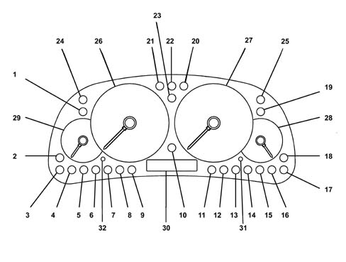
The diagram shows the location of the warning lights in the instrument panel
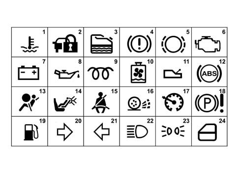
| NUMBER | WARNING LIGHT NAME | COLOUR | TYPE |
|---|---|---|---|
| 1 | Engine coolant overheating | RED | M |
| 2 | CODE system failure | AMBER | PL |
| 3 | Water in diesel filter warning light | AMBER | PH |
| 4 | Hanbrake/brake fluid level/EBD | RED | PL |
| 5 | Brake pad wear | RED | PL |
| 6 | Injection/EOBD failure | AMBER/RED | PL |
| 7 | Insufficient battery charge | RED | PL |
| 8 | Engine oil pressure | RED | PL |
| 9 | Heater plugs | AMBER | PL |
| 10 | Radiator coolant low level warning light | RED | PL |
| 11 | Automatic transmission failure | RED | M OPT |
| 12 | ABS | AMBER | PI OPT |
| 13 | Air Bag failure warning light | RED | PI |
| 14 | Passenger Air Bag disabling | AMBER | PL OPT |
| 15 | Seat belts not fastened | RED | PL OPT |
| 16 | Traction Control/ASR failure | AMBER | PL OPT |
| 17 | Cruise control on | GREEN | PL OPT |
| 18 | EPB failure (activated to earth +30 supply connected) | RED | PL OPT |
| 19 | Fuel reserve | AMBER | M |
| 20 | Right direction indicator | GREEN | PH |
| 21 | Left direction indicator | GREEN | PH |
| 22 | Main beam headlamps | BLUE | PL |
| 23 | Side lights | GREEN | PH |
| 24 | Doors open | RED | PL OPT |
| 25 | Spare 1 | PL | |
| 26 | Electronic speedometer | ||
| 27 | Electronic rev counter | ||
| 28 | Fuel level gauge | ||
| 29 | Engine coolant temperature gauge | ||
| 30 | Milometer LCD | ||
| 31 | Odometer and service button | ||
| 32 | Time adjustment button |
- PL = warning light activated at low level;
- PH = warning light activated at high level;
- PI = intelligent type warning light;
- M = warning light activated by micro-controller;
Instrument panel connectors
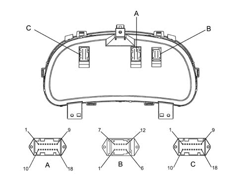
The instrument panel and the PIN OUT are illustrated in the diagram below
| PIN | SIGNAL |
|---|---|
| 1 | Speedometer 1 repetition for CCM |
| 2 | Water in diesel filter warning light |
| 3 | CODE warning light |
| 4 | Instrument earth |
| 5 | Speedometer impulse generator earth |
| 6 | Handbrake applied warning light |
| 7 | Injection/EOBD failure warning light |
| 8 | Reserved for Magneti Marelli |
| 9 | Engine coolant temperature sensor input |
| 10 | Direct supply (+30) |
| 11 | Main beam headlamps warning light |
| 12 | Supply controlled by ignition (+15) |
| 13 | Fuel level sensor earth |
| 14 | Fuel level sensor earth input |
| 15 | Speedometer input from impulse generator / CCA |
| 16 | Engine coolant overheating warning light CCM |
| 17 | Rev counter signal input |
| 18 | Radiator coolant level warning light |
| PIN | SIGNAL |
|---|---|
| 1 | Alternator recharging warning light |
| 2 | Brake pad wear warning light |
| 3 | Insufficient brake fluid level warning light |
| 4 | Heater plugs warning light |
| 5 | Right direction indicators warning light |
| 6 | Left direction indicators warning light |
| 7 | Insufficient engine oil pressure warning light |
| 8 | Air Bag failure warning light |
| 9 | Side lights warning light |
| 10 | Fuel reserve repeater |
| 11 | Engine oil level sensor/M.M.E.O.L. input |
| 12 | Engine oil level sensor earth |
| PIN | SIGNAL |
|---|---|
| 1 | Doors open warning light |
| 2 | Dimmer input (preparation) |
| 3 | Doors open warning light |
| 4 | Not connected |
| 5 | Not connected |
| 6 | ZF automatic transmission input |
| 7 | ABS failure warning light |
| 8 | EBD failure warning light |
| 9 | Cruise Control failure warning light |
| 10 | Spare warning light 1 |
| 11 | Main beam headlamps warning light |
| 12 | Speedometer repeater 4 |
| 13 | Speedometer repeater 3 (preparation) |
| 14 | Speedometer repeater 2 |
| 15 | Speedometer input from tachograph [b7] |
| 16 | Traction Control/ASR failure warning light |
| 17 | Passenger Air Bag disabled warning light |
| 18 | Not connected |
Lighting system
The instrument panel backlighting is activated when the signal from the lights is received, whilst the panel is not lit up when the headlamps are off. No other lighting control strategy is active on the panel while the mileometer display is automatically back-lit when the key is turned on.Odometer
The milometer is the digital electronic type with an LCD (liquid crystal display) with 1 line.The milometer display is illustrated in the diagram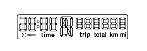
- (a) when the total mileage is displayed pressing the button for between 0.1 seconds and 2 seconds produces a switching to the trip mileage when it is released;
- (b) when the trip mileage is displayed, pressing the button briefly (in other words between 0.1 and 2 seconds) produces a switch to the total mileage when the button is released; pressing the button for a while (between 2 and 5 secs) inolves zeroing the trip mileage displayed.
Planned maintenance
The servicing function lets the user know when the vehicle is ready for service when the distance or time parameters approach the deadline set for the engine and application type.Distance and time parameters definitionThe parameters used for calculating the services are the distance travelled and time.The distance travelled is calculated using the vehicle speed input with an upper limit of 99999 Km and the time is indicated in days and taken from the clock function.There is a spanner symbol for the servicing function that appears each time the ignition is switched on if the conditions for the service displayed below have been reached.| MILEAGE AND TIME REMAINING UNTIL THE SERVICE | SPANNER KEY FOR THE FIRST 5 SECONDS AFTER THE IGNITION IS TURNED ON | SPANNER KEY FOR 5 SECONDS AFTER THE IGNITION IS TURNED ON |
|---|---|---|
| Km > 2000 TIME > 30 DAYS | ON | OFF |
| Km > 2000 TIME < 30 DAYS | ON | ON |
| 0 < Km < 2000 TIME = ELAPSED | ON | ON |
| Km = 0 TEMPO = ELAPSED | FLASHING | FLASHING FOR THE DURATION OF THE DISPLAY, THEN ON CONSTANTLY |
Engine oil level sensor
When the ignition is turned on the milometer displays the engine oil level for five seconds.This level is read by measuring the voltage at the sensor located located in the engine oil sump. The difference in power measured allows the level to be calculated. The type of display is capable of managing the signal coming from the sensor and displaying the oil level state as illustrated below.Speedometer
The speedometer reading makes it possible to show speeds of between 0 Km/h and 180 Km/h and imperial units are also shown on the scale.The instrument panel receives the speedometer signal from an impulse generator created by means of a Hall effect sensor fitted on the gearbox flywheel.The speedometer function is achieved by means of a stepping motor operated by an electronic circuit with a clockwise direction of rotation.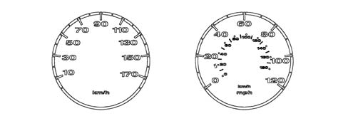
Rev counter
The engine rev counter reading makes it possible to display values of between 0 and 6000 rpmThe engine rpm signal comes from an injection/ignition electronic control unit. The instrument panel acquires this signal operating the rev counter by means of a stepping motor managed by an electronic circuit with a clockwise direction of rotation.
Indicator recovery logics (stepping motors)
The recovery of any steps lost by the instrument panel is guaranteed for each individual indicator.The "return to zero" logic for the pointers is verified each time the battery is disconnected/reconnected. The same recovery function is also used each time the ignition is turned on and off.Clock function
The clock is the digital type with an LCD with figures with 7 segments.The time is shown in hours and minutes starting from 0:00 up to 23:59 when it then returns to 0:00.After each time the battery is connected or after the microprocessor is reset, the clock shows 0:00.If the clock adjustment button (32) is pressed for more than 2 secs, access is gained to the "clock adjustment" mode when it is released. The hours and minutes are adjusted in this mode, pressing the button for more than 1 sec increases the minutes with the time between one increment and the next varying in a linear fashion. If the button is pressed for more than 3 seconds, the increases are in 10 minute steps (approximately to the next tenth) for both the minutes and the hours. If no corrections are made for 5 seconds, the "clock adjustment" mode is exited.Engine coolant temperature gauge
The engine coolant temperature reading is taken by means of a stepping motor operated by an electronic circuit with a clockwise direction of rotation with a scale that starts at "C" which corresponds to 50 degrees centrigrade and ends at "H" which is around 130 degrees centrigrade.The movement of the pointer in the red sector corresponds to a dangerous temperature of 120°C. With the ignition on the pointer shows the temperature reading according to the following logic:- if T < 50 °C the pointer should be on the first scale reference.
- if T > 50 °C, the pointer should be positioned on the reference corresponding the temperature value measured.

WARNING LIGHTS
Specifications
The instrument panel control unit turns the warning lights on or off by means of commands downloaded directly from sensors of components connected to the control unit.When a fault occurs, the warning lights come on in accordance with a planned strategy, but some warning lights also come on with the key ON for a period no longer than four seconds to indicate the check status of the system to which they are connected.The control panel is also equipped with some smart warning lights that are used for the air bag system fault warning light and ABS warning lightFuel level and reserve warning light
The fuel gauge shows the readings as a percentage.The warning light comes on for four seconds (check stage) when the ignition is swiched on and remains on whilst the fault is received.
Fuel reserve warning light
The fuel reserve condition is signalled when the fuel level reading reaches a preset value.In order to avoid tiresome flashing, the warning light comes on with a (time hysteresis) delay of 50 seconds from the moment the reserve condition is reached and goes out with a delay of 30 seconds from when the condition no longer exists.
Engine coolant temperature warning light
The warning light comes on for four seconds (check stage) when the ignition is swiched on and remains on whilst the fault is received.If the warning light is on this indicates that the engine coolant temperature is too high. The engine coolant overheating signal is sent to the instrument panel directly by the engine management control unit. The temperature is controlled by means of an on/off sensor.
Automatic transmission failure
The warning light comes on for four seconds (check stage) when the ignition is swiched on and remains on whilst the fault is received.The automatic transmission failure signal is produced by the automatic transmission control unit which converses with the panel by means of a serial line at 500 bit/sec.The gear engaged is displayed by means of liquid crystal display segements which readings alternating between the symbols "P", "R", "N", "D", "1", "2", "3" and "4".
Minimum engine oil pressure warning light
The minimum engine oil pressure fault signal comes from a normally open type on/off sensor that operates according to the following logic:- With the contact open the pressure is above the minimum level (warning light off)
- With the contact closed the pressure is below the minimum value (warning light on)

Heater plugs warning light
The heater plugs warning light (diesel engines only) comes on for four seconds when the ignition is switched on and its operation is determined by the receipt of a message from the CCM with the light on constantly when the ignition is switched on and flashing when the heater plugs failure signal is received.The warning light remains off when the message is received from the CCM even during the check stage.
Injection/EOBD failure warning light
The type of signal coming from the engine management control unit remains activated in failure conditions switching on the amber/red LED (depending on the version) in the panel. The EOBD warning lights remains off whilst the engine is being started as long as the fault conditions do not exist; in this case the warning light remains activated.
CODE warning light
The impulse that signals the failure of the alarm signal comes from the CODE control unit in which case the LED lights up amber; the timing of this warning light is managed by the actual CODE control unit according to the operating stages.
Passenger Air Bag warning lights
With the key ON, the yellow passenger side air bag disabled warning light comes on for about four seconds (initial self-diagnosis stage). If the control unit detects a fault in the warning light, it saves the fault code, turns on the fault warning light and maintains the passenger side airbag module disabled. System operation is restored by means of an EXAMINER as with the fault warning light.Once the initial self-diagnostic stage of 4 seconds has elapsed, if the key-operated disablement switch is turned OFF, the warning light stays on to indicate (passenger module disabled). If no faults are present, the warning light flashes for another four seconds and then goes off to indicate (passenger module enabled). The passgner Air Bag deactivated signal is produced by the Air Bag control unit.
ASR/TC warning light
The operating/failure signal is produced by the ABS control unit. The LED on constantly indicates either the failure of the ASR/TC system or that the system has been disabled by the user via the special button. If the light is on intermittently, this indicates that the ASR/TC is switched on.
Brake pad wear warning light
This red coloured warning light in the panel signals brake pad wear; it is switched on by means of a conductor countersunk into the pad friction material. When the conductor reaches the surface of the pad as a result of wear, it is short circuited to each by the brake disc during braking.
ABS failure warning light
The red warning light signals an ABS failure and comes on either when the fault message is received from the ABS control unit or if there is a fault in the circuit that connects the warning light to the ABS control unit.
Recharging warning light
This red warning light remains on for about 4 seconds when the ignition is switched on during the check stage and indicates that the alternator is not working properly.
Cruise control on warning light
The signal is produced by the robotized gearbox control unit and the warning light remains on when this signal is switched on.
EBD/brake fluid level/handbrake applied warning light
The handbrake warning light comes on constantly when the message is received from the handbrake applied sensor.The brake fluid warning light comes on constantly (with the handbrake switched off) when the insufficient brake fluid level message is received.The EBD failure warning light comes on constantly with the handbrake switched off when the EBD failure message is received.
Doors open warning light
The warning light comes on when the signal is received coming from a sensor activated to earth that one or more doors are open. The warning light remains on until the doors are closed.
Radiator coolant low level warning light
The low radiator coolant level signal comes from a normally open open/closed type sensor and is managed according to the following logic:- Contact open: radiator coolant above the minimum level.
- Contact closed: minimum radiator coolant level.

Seat belt not fastened warning light
If the red seat belts warning light is on, this indicates that the seat belt is not fastened and it operates according to the following logic:- with the ignition ON, if the driver has not fastened their seat belt, the warning light comes on constantly.
- with the ignition ON, if the seat belt is fastened before the ignition is switched on the warning light remains off.
- if the seat belt is unfastened whilst driving, the LED comes on constantly.

Main beam headlamp warning light
The warning light signalling that the main beam headlamps are on is operated by receiving a message from the steering column switch unit control unit that the main beam headlamps are on/off.
Side lights warning light
The warning light signalling that the side lights are on is operated by receiving a message from the steering column switch unit control unit that the side lights are on/off.Direction indicator warning light
The operation of the direction indicators warning light is determined by receiving a message that the direction indicators or the hazard warning lights are activated (in the latter case the warning light comes on even if the ignition is switched off) with the flashing frequency dictated by the steering column switch unit control unit. The warning light signals the function by lighting up the signals for the same family.
Water in fuel filter warning light
The warning light uses an LED and remains on constantly after the check stage if it receives the signal from the water in the diesel filter sensor.
AIR BAG system failure warning light
- At the key ON, the (red) fault warning light comes on for about four seconds (initial self-diagnosis stage) and then goes off. If the control unit detects a fault in the warning light, it saves the corresponding fault code. If no system faults are detected at key on and no fault conditions are present in the fault memory, the warning light goes off after four seconds of self-diagnosis. Otherwise it stays on until key off.The warning light stays or comes on durng normal car operation in the following cases:- the control unit detects a fault in the airbag system;
- the control unit detects a crash with system activation;
- when a fault is detected in the warning light connection circuit.