FIAT / DUCATO 244eLearn workshop manual · English · Offline edition
Procedures

1004D10 POWER UNIT (MANUAL GEARBOX), REMOVED, REMOVE AND RE-BUILD

Engines: 2.0 16V, 2.0 JTD 8V, 2.3 JTD 16V, 2.8 JTD 8V
Engines: 2.0 16V

RemovingManual illustration 20

RefittingManual illustration 21
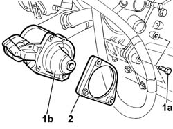
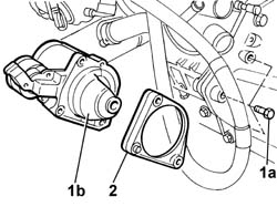
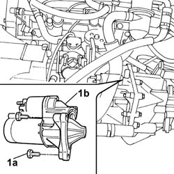
1. Undo retaining bolts (1a) and remove starter motor (1b).
Manual illustration 244000708
Engines: 2.0 16V
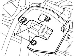
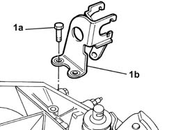
1. Undo the fixing nuts (1a) and remove the clutch actuator cylinder bracket (1b).
Manual illustration 244000709
Engines: 2.0 16V
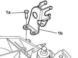
1. Undo the bolts and the nut (1a) fixing the mounting bracket for the gear selection and engagement cables (1b).
Manual illustration 244000710
Engines: 2.0 16V
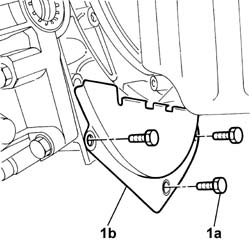
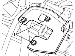
1. Undo the fixing bolts (1a) and remove the engine flywheel guard (1b).
Manual illustration 244000711
Engines: 2.0 16V
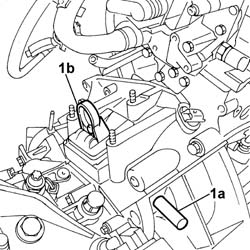
1. Release the shaft for the fork lever (1a) using the special tool and release the fork (1b).
Manual illustration 244000499DescriptionCodeFunction
.Extractor1.870.873.000Fork pin removal
Manual illustration 244000712
Engines: 2.0 16V
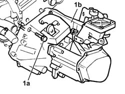
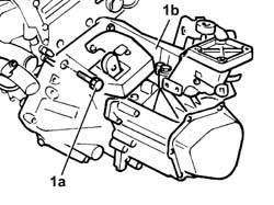
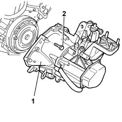
1. Undo fastenings (1a) and remove the gearbox and differential (1b).
Manual illustration 244000713
Engines: 2.0 16V

RefittingManual illustration 21

RemovingManual illustration 20
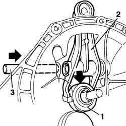
1. Position the thrust bearing on the gearbox mainshaft sleeve.2. Check the release lever is positioned correctly in the thrust bearing.3. Insert the release lever retaining shaft.
Manual illustration 244000714
Engines: 2.0 16V
- Fit the gearbox differential unit and tighten the bolts to torque.- Fit the mounting bracket and support for the gear selection and engagement cables.- Fit the clutch actuator cylinder mounting bracket in place.- Fit the flywheel guard and tighten the fixing bolts.- Fit the starter motor in position and tighten to torque.
Engines: 2.0 16V, 2.0 JTD 8V, 2.3 JTD 16V, 2.8 JTD 8V

RemovingManual illustration 20

RefittingManual illustration 21
1. Undo retaining bolts (1a) and remove starter motor (1b).2. Remove the spacer from the gearbox.
Manual illustration 244000715
Engines: 2.0 16V, 2.0 JTD 8V, 2.3 JTD 16V, 2.8 JTD 8V
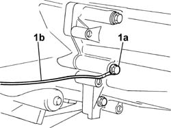
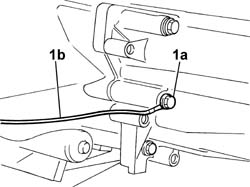
1. Unscrew retaining bolt (1a) and disconnect earth lead (1b) from the gearbox bell housing.
Manual illustration 244000716
Engines: 2.0 16V, 2.0 JTD 8V, 2.3 JTD 16V, 2.8 JTD 8V
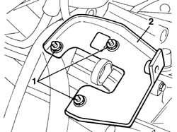
1. Undo the fixing nuts.2. Remove the operating cylinder mounting bracket on the bellhousing.
Manual illustration 244000717
Engines: 2.0 16V, 2.0 JTD 8V, 2.3 JTD 16V, 2.8 JTD 8V
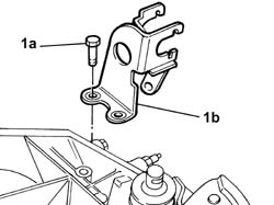
1. Unscrew bolts and nut (1a) and remove the mount for gear selection and engagement cables (1b).
Manual illustration 244000718
Engines: 2.0 16V, 2.0 JTD 8V, 2.3 JTD 16V, 2.8 JTD 8V
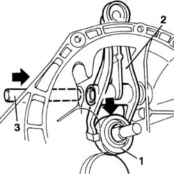
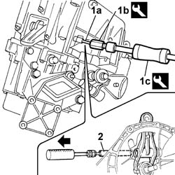
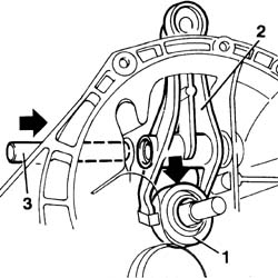
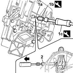
1. To remove the fork lever pin, use a M6 x 1 bolt (1a) fitted, in turn, into connector (1b) screwed into driver (1c).
Manual illustration 244000499DescriptionCodeFunction
1bExtractor1.860.959.000Clutch control fork lever pin removal
Manual illustration 244000499DescriptionCodeFunction
1cMallet1.847.017.001Clutch control fork lever pin removal
2. Tighten the resulting tool to the pin and exercise a pulling force in the arrowed direction (toward the operator) to remove the fork lever retaining shaft.
Manual illustration 244000719
Engines: 2.0 16V, 2.0 JTD 8V, 2.3 JTD 16V, 2.8 JTD 8V
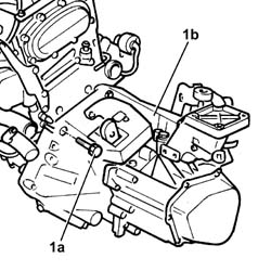
1. Undo fastenings (1a) and remove the gearbox and differential (1b).
Manual illustration 244000720
Engines: 2.0 16V, 2.0 JTD 8V, 2.3 JTD 16V, 2.8 JTD 8V

RefittingManual illustration 21

RemovingManual illustration 20
1. Position the thrust bearing on the gearbox mainshaft sleeve.2. Check the release lever is positioned correctly in the thrust bearing.3. insert the release lever retaining shaft.
Manual illustration 244000721
Engines: 2.0 16V, 2.0 JTD 8V, 2.3 JTD 16V, 2.8 JTD 8V
- Fit the gearbox-differential unit and tighten the fixing nuts and bolts to torque.
Manual illustration 244000559Value - daNmFasteningComponentØ  
.7BoltMANUAL GEARBOX/DIFFERENTIALM12
Manual illustration 244000559Value - daNmFasteningComponentØ  
.6NutMANUAL GEARBOX/DIFFERENTIALM10
- Fit the gear selection and engagement cable retaining and mount bracket.- Fit the release cylinder bracket to the gearbox.- Position the starter motor spacer.- Fit the starter motor and tighten the fixing bolts to torque.
Manual illustration 244000559Value - daNmFasteningComponentØ  
.2BoltSTARTER MOTORM8
Engines: 2.0 16V, 2.0 JTD 8V, 2.3 JTD 16V, 2.8 JTD 8V

RemovingManual illustration 20

RefittingManual illustration 21
1. Undo retaining bolts (1a) and remove starter motor (1b).2. Remove the spacer from the gearbox.
Manual illustration 244000722
Engines: 2.0 16V, 2.0 JTD 8V, 2.3 JTD 16V, 2.8 JTD 8V
1. Unscrew retaining bolt (1a) and disconnect earth lead (1b) from the gearbox bell housing.
Manual illustration 244000723
Engines: 2.0 16V, 2.0 JTD 8V, 2.3 JTD 16V, 2.8 JTD 8V
1. Undo the fixing nuts.2. Remove the operating cylinder mounting bracket on the bellhousing.
Manual illustration 244000724
Engines: 2.0 16V, 2.0 JTD 8V, 2.3 JTD 16V, 2.8 JTD 8V
1. Unscrew bolts and nut (1a) and remove the mount for gear selection and engagement cables (1b).
Manual illustration 244000725
Engines: 2.0 16V, 2.0 JTD 8V, 2.3 JTD 16V, 2.8 JTD 8V
1. To remove the fork lever pin, use a M6 x 1 bolt (1a) fitted, in turn, into connector (1b) screwed into driver (1c).
Manual illustration 244000499DescriptionCodeFunction
1bExtractor1.860.959.000Clutch control fork lever pin removal
Manual illustration 244000499DescriptionCodeFunction
1cMallet1.847.017.001Clutch control fork lever pin removal
2. Tighten the resulting tool to the pin and exercise a pulling force in the arrowed direction (toward the operator) to remove the fork lever retaining shaft.
Manual illustration 244000726
Engines: 2.0 16V, 2.0 JTD 8V, 2.3 JTD 16V, 2.8 JTD 8V
1. Undo fastenings (1a) and remove the gearbox and differential (1b).
Manual illustration 244000727
Engines: 2.0 16V, 2.0 JTD 8V, 2.3 JTD 16V, 2.8 JTD 8V

RefittingManual illustration 21

RemovingManual illustration 20
1. Position the thrust bearing on the gearbox mainshaft sleeve.2. Check the release lever is positioned correctly in the thrust bearing.3. insert the release lever retaining shaft.
Manual illustration 244000728
Engines: 2.0 16V, 2.0 JTD 8V, 2.3 JTD 16V, 2.8 JTD 8V
- Fit the gearbox-differential unit and tighten the fixing nuts and bolts to torque.
Manual illustration 244000559Value - daNmFasteningComponentØ  
.7BoltMANUAL GEARBOX/DIFFERENTIALM12
Manual illustration 244000559Value - daNmFasteningComponentØ  
.6NutMANUAL GEARBOX/DIFFERENTIALM10
- Fit the gear selection and engagement cable retaining and mount bracket.- Fit the release cylinder bracket to the gearbox.- Position the starter motor spacer.- Fit the starter motor and tighten the fixing bolts to torque.
Manual illustration 244000559Value - daNmFasteningComponentØ  
.2BoltSTARTER MOTORM8
Engines: 2.0 JTD 8V

RemovingManual illustration 20

RefittingManual illustration 21
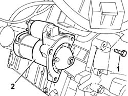
1. Undo retaining bolts (1a) and remove starter motor (1b).
Manual illustration 244000729
Engines: 2.0 JTD 8V
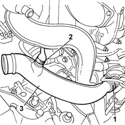
1. Disconnect the pipe from the band on the turbocharger (1a) and with vapour recovery pipe (1b).2. Remove the turbocharger air intake pipe.
Manual illustration 244000730
Engines: 2.0 JTD 8V
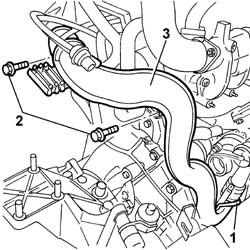
1. Disconnect the band from the turbocharger.2. Undo the bolts securing the pipe to the mount.3. Remove the rigid air delivery section from turbocharger to engine.
Manual illustration 244000731
Engines: 2.0 JTD 8V
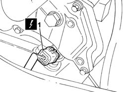
1. Disconnect the electrical connection for the rpm sensor.
Manual illustration 244000463DescriptionConnector
1Rpm sensorK046
Manual illustration 244000732
Engines: 2.0 JTD 8V
1. Undo fastenings (1a) and remove the gearbox and differential (1b).
Manual illustration 244000733
Engines: 2.0 JTD 8V

RefittingManual illustration 21

RemovingManual illustration 20
- Fit the gearbox-differential unit and tighten the nuts and bolts to torque.
Manual illustration 244000559Value - daNmFasteningComponentØ  
.7BoltMANUAL GEARBOX/DIFFERENTIALM12
Manual illustration 244000559Value - daNmFasteningComponentØ  
.6NutMANUAL GEARBOX/DIFFERENTIALM10
- Connect the electrical connection for the rpm sensor.
Manual illustration 244000463DescriptionConnector
.Rpm sensorK046
- Fit the rigid air delivery section from turbocharger to engine.- Tighten the bolts securing the pipe to the mount and connect the band to the turbocharger.- Fit the air inlet pipe to the turbocharger and secure to the turbo using a band.- Connect the oil vapour recovery pipe.- Fit the starter motor and tighten the bolts to torque.
Manual illustration 244000559Value - daNmFasteningComponentØ  
.4.5BoltSTARTER MOTORM8