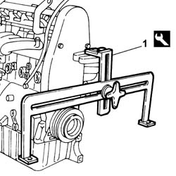
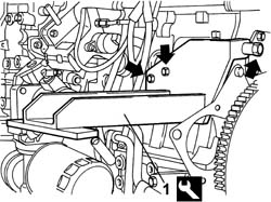
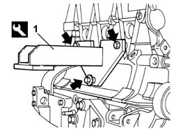
- Secure and support the engine using a hydraulic lift fitted with chains.1. Fit the tool on the timing side engine mounting bracket.
Description
Code
Function
1
Brackets
1.861.001.032
Engine overhaul stand support
Engines: 2.0 16V
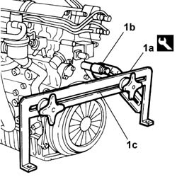
1. Fit the tool (1a) using suitable length bolts (1b) and (1c) in the flywheel side crankcase openings.
Description
Code
Function
1a
Brackets
1.861.001.034
Engine overhaul stand support
Engines: 2.0 16V
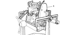
1. Fit the engine, complete with brackets, on the overhaul stand.
Engines: 2.0 16V
- Release the engine from the hoist.- Secure and support the engine using a hydraulic lift fitted with chains.- Undo the fastenings and remove the engine complete with supporting tools.- Undo the fastenings and remove the engine supporting tools, then replace them.
Description
Code
Function
.
Brackets
1.861.001.032
Engine overhaul stand support
Description
Code
Function
.
Brackets
1.861.001.034
Engine overhaul stand support
Engines: 2.3 JTD 16V
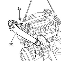
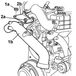
- Secure and support the engine using a hydraulic hoist fitted with chains.1. Undo the bolt and release the retaining collar.2. Undo nut (2a) and remove the cold air intake pipe (2b) to the turbocharger.
Engines: 2.3 JTD 16V
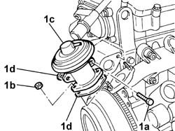
1. Undo bolts (1a), nuts (1b) and remove the EGR valve (1c) with gaskets (1d).
Engines: 2.3 JTD 16V
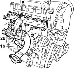
1. Unscrew the fittings and disconnect the oil input pipe to the turbocharger (1a) and the oil return pipe to the sump (1b).2. Undo the nuts (2a) and remove the exhaust manifold complete with turbo unit (2b).3. Remove the seal.
Engines: 2.3 JTD 16V
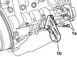
1. Undo bolts (1a) and remove the intermediate shaft mount (1b).
Engines: 2.3 JTD 16V
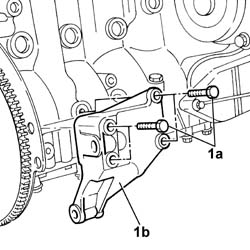
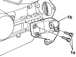
1. Undo bolts (1a) and remove the rear bracket joining the gearbox to the engine (1b).
Engines: 2.3 JTD 16V
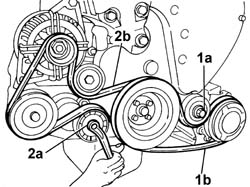
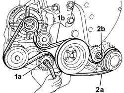
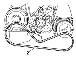
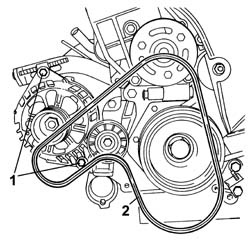
1. Loosen tensioner bolt (1a) and remove compressor drive belt (1b).2. Use a wrench to adjust automatic tensioner (2a) and remove alternator and power steering pump drive belt (2b).
Engines: 2.3 JTD 16V
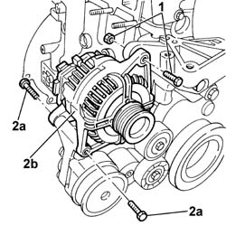
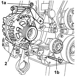
1. Undo the upper bolt.2. Undo the bolts (2a) and remove the alternator (2b).
Engines: 2.3 JTD 16V
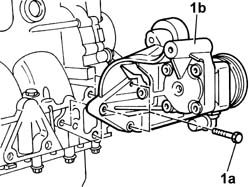
1. Undo the bolts (1a) and remove the power steering pump (1b) complete with mount and pulleys.
Engines: 2.3 JTD 16V
1. Undo bolts (1a) and remove the front bracket joining the gearbox to the engine (1b).
Engines: 2.3 JTD 16V
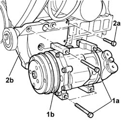
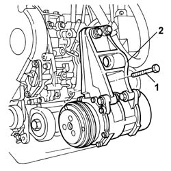
1. Undo the bolts (1a) and remove the air conditioner compressor (1b).2. Undo bolts (2a) and remove the air conditioner compressor mount (1b).
Engines: 2.3 JTD 16V
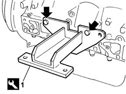
1. Fit the tool for supporting the engine, exhaust side.
Description
Code
Function
1
Brackets
1.870.852.000
Engine overhaul stand support
Engines: 2.3 JTD 16V
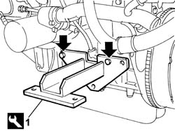
1. Prise off the fuel pipe anchorage bracket and fit the tool for supporting the engine on the intake side.
Description
Code
Function
1
Brackets
1.870.852.000
Engine overhaul stand support
Engines: 2.3 JTD 16V
- Fit the engine on the overhaul stand.- Release the engine from the hoist.- Drain the engine oil from the plug on the oil sump.- Secure and support the engine using a hydraulic hoist fitted with chains.- Undo the fastenings and remove the engine from the overhaul stand complete with supporting tools.- Undo the retaining bolts and remove the engine support tools.
Description
Code
Function
.
Brackets
1.870.852.000
Engine overhaul stand support
- Fit the air conditioner compressor mount and tighten the retaining bolts to the specified torque.
Value - daNm
Fastening
Component
Ø
.
2.5
Bolt
COMPRESSOR MOUNT (AC)
M8 X 1.25
- Fit the air conditioner compressor and tighten the retaining bolts to the specified torque.
Value - daNm
Fastening
Component
Ø
.
2.5
Bolt
AIR CONDITIONER ASSEMBLY COMPRESSOR
M8 X 1.25
- Fit the front bracket joining the gearbox to the engine and tighten the retaining bolts.- Fit the power assisted steering pump complete with support and pulleys and tighten the bolts to torque.
Value - daNm
Fastening
Component
Ø
.
2.5
Bolt
POWER STEERING PUMP
M8 X 1.5
- Fit the alternator and tighten the retaining bolt and screws to torque.
Value - daNm
Fastening
Component
Ø
.
(upper fastening) 4.9
Bolt
ALTERNATOR ASSEMBLY
M10 X 1.5
Value - daNm
Fastening
Component
Ø
.
(lower fastening) 4.9
Bolt
ALTERNATOR ASSEMBLY
M10 X 1.5
1. Fit the power steering pump and alternator drivebelt (1b) by using a wrench to adjust automatic belt tensioner (1a).2. Fit the air conditioner compressor belt (2a) and adjust tensioner by means of tensioner (2b).
Engines: 2.3 JTD 16V
- Fit the rear bracket joining the gearbox to the engine and tighten the retaining bolts.- Fit the intermediate shaft mount and tighten the retaining bolts to the specified torque.
Value - daNm
Fastening
Component
Ø
.
5
Bolt
FRONT DRIVE SHAFT BEARING MOUNT
M10 X 1.25
- Position a new gasket, fit the exhaust manifold complete with turbocharger and tighten the retaining bolts to the specified torque.
Value - daNm
Fastening
Component
Ø
.
2.2
Bolt
EXHAUST MANIFOLD/S
M8 X 1.25
- Tighten the connectors for the oil inlet pipe to the turbocharger and oil return pipe to the sump to the specfied torque.
Value - daNm
Fastening
Component
Ø
.
(Cylinder head) 0.9
Connector
COOLANT HOSES TURBOCHARGER
1/4" X 1.3
Value - daNm
Fastening
Component
Ø
.
(Cylinder block/crankcase) 1.7
Connector
COOLANT HOSES TURBOCHARGER
3/8" X 1.3
- Fit new gaskets, fit the EGR valve and tighten the retaning bolts and nuts- Position the cold air intake pipe to the turbocharger complete with collar and tighten the retaining collar nut and bolt.- Release the engine from the hoist.
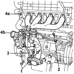
1. Undo the nuts fixing the exhaust manifold bracket to the cylinder block/crankcase.2. Undo the engine oil pressure sender unit and release the fluid inlet pipe from the turbocharger.3. Loosen the retaining bands and disconnect the sump fluid return pipe from the turbocharger.4. Undo the nuts (4a) and remove the exhaust manifold (4b) complete with turbo unit.- Remove the gasket.
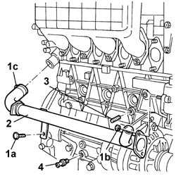
1. Undo the fixing bolts (1a), undo the fixing nuts (1a) and loosen the band (1c).2. Remove the thermostat-water pump pipe.3. Remove the crankcase plug.4. Undo the turbocharger fluid return connector from the crankcase.
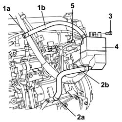
1. Loosen the band (1a) and disconnect the oil vapour recovery pipe from the cylinder head (1b).2. Loosen the band (2a) and disconnect the condensation oil recovery pipe (2b) from the crankcase.3. Undo the oil vapour separator fixing bolts.4. Remove the engine oil vapour separator complete with pipes.5. Undo the bolt fixing the coolant pipes to the heat exchanger.6. Fold the coolant pipes to the heat exchanger downwards.
- Fit the engine on the overhaul stand.- Release the engine from the hoist.- Secure and support the engine using a hydraulic hoist fitted with chains.- Undo the fastenings and remove the engine complete with supporting tools.- Undo the fastenings and remove the engine supporting tools, then replace them.- Position the heat exchanger coolant pipes and fasten them tightening the bolt.- Fit the oil vapour separator and secure it using the bolts.- Connect the oil vapour recovery pipe to the cylinder head and fasten it using the band.- Connect the condensation oil vapour recovery pipe to the crankcase and fasten it using the band.- Fit the support complete with compressor and secure it without tightening the bolts to torque.- Loosen the two bolts fixing the auxiliary unit, then tighten all the bolts to torque.
Value - daNm
Fastening
Component
Ø
.
(engine crankcase side) 2.5
Bolt
auxiliary unit
M8
Value - daNm
Fastening
Component
Ø
.
(engine crankcase side) 6.0
Bolt
auxiliary unit
M12
- Fit the alternator complete with belt tension adjustment device and secure it without tightening the bolts.- Fit the thermostat-pump pipe and fasten it using the bolts, nuts and band.- Fit the intermediate propeller shaft support.
Value - daNm
Fastening
Component
Ø
.
(cylinder block/crankcase side) 2.1
Nut
PROPELLER SHAFT INTERMEDIATE SUPPORT
M8
- Tighten the turbocharger fluid return connector to the crankcase.- Fit the exhaust manifold gasket.- Fit the exhaust manifold, complete with turbocharager and secure it tightening the nuts to the recommended torque.
Value - daNm
Fastening
Component
Ø
.
(Cylinder head side) 2.1 -2.6
Nut
EXHAUST MANIFOLD/S
M8
- Connect the oil inlet pipe to the turbocharger and tighten the oil pressure sender unit.- Connect the sump oil return pipe to the turbocharger and secure it using the band.- Tighten the nuts fixing the exhaust manifold bracket to the cylinder block/crankcase.- Fit the inlet pipe and secure it using the bracket.- Fit the alternator drive belt.- Fit the compressor drive belt.
Engines: 2.0 JTD 8V
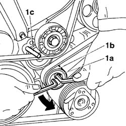
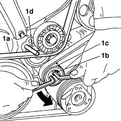
- Secure and support the engine using a hydraulic hoist fitted with chains.1. Loosen bolt (1a), then use a ¼" box wrench to adjust tensioner (1b) until a 4 mm diameter pin (1c) can be fitted into the reference hole.
Engines: 2.0 JTD 8V
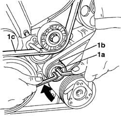
1. Leave tensioner (1b) and provisionally tighten bolt (1a), then remove accessory drivebelt (1c).
Engines: 2.0 JTD 8V
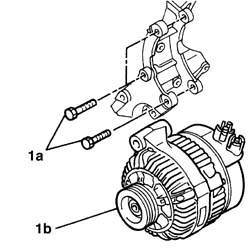
1. Undo bolts (1a) and remove alternator (1b).
Engines: 2.0 JTD 8V
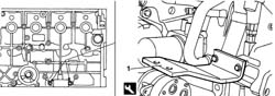
1. Fit the tool into the holes on the injection side engine block.
Description
Code
Function
1
Brackets
1.861.001.040
Engine overhaul stand support
Engines: 2.0 JTD 8V
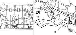
1. Fit plate (1a) into the holes on the exhaust side engine block, then fit tool (1b) to the plate.
Description
Code
Function
1b
Brackets
1.861.001.040
Engine overhaul stand support
Engines: 2.0 JTD 8V
- Fit the engine on the overhaul stand.- Release the engine from the hoist.- Secure and support the engine using a hydraulic hoist fitted with chains.- Undo the fastenings and remove the engine complete with supporting tools.- Undo the fastenings and remove the engine supporting tools, then replace them.
Description
Code
Function
.
Brackets
1.861.001.040
Engine overhaul stand support
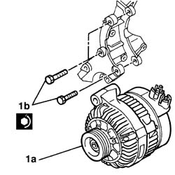
1. Fit alternator (1a) and tigten bolts (1b).
Engines: 2.0 JTD 8V
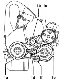
1. Version without air conditioner: fit the accessory drivebelt in the following order: (1a) crankshaft pulley, (1b) tensioner with wear gauge, (1c) power steering pump, (1d) tensioner with tension regulator, (1e) alternator, (1f) idler gear.
Engines: 2.0 JTD 8V
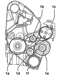
1. Version with air conditioning: fit the accessory drivebelt in the following order: (1a) crankshaft pulley, (1b) tensioner with wear gauge, (1c) power steering pump, (1d) tensioner with tension regulator, (1e) alternator, (1f) air conditioner compressor.
Engines: 2.0 JTD 8V
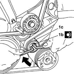
1. Fit accessory drivebelt (1a), loosen bolt (1b), then use a ¼" box wrench to adjust tensioner (1c) until a 4 mm diameter pin (1d) can be fitted into the reference hole
Engines: 2.0 JTD 8V
1. Leave tensioner (1a) and tighten bolt (1b) to the specified torque.