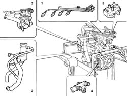
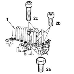
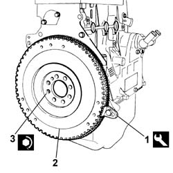
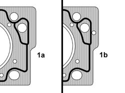
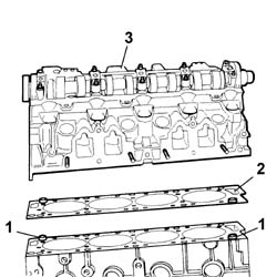
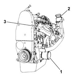
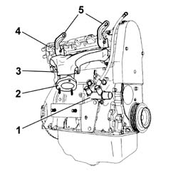
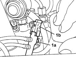
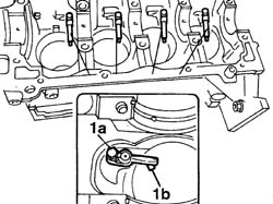
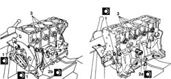
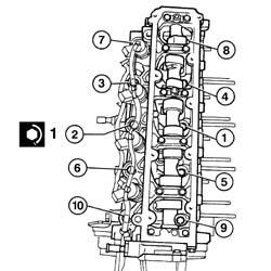
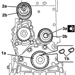
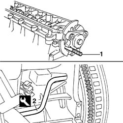
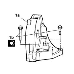
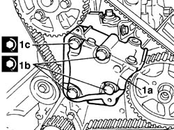
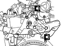
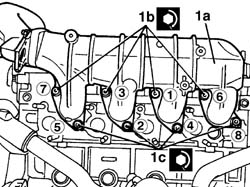
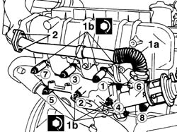
1. Remove the spark plug leads and bracket.2. Remove the oil vapour separator complete with pipes.3. Remove the intake manifold with throttle body and fuel manifold.4. Remove the engine coolant intake manifold.5. Remove the ignition coil.
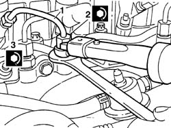
Engines: 2.0 16V
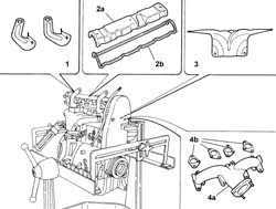
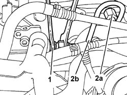
1. Remove the engine mounting brackets.2. Remove cam cover (2a) and gasket (2b).3. Remove the exhaust manifold heat shield.4. Remove exhaust manifold (4a) and gaskets (4b).
Engines: 2.0 16V
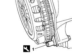
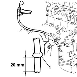
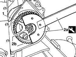
- Remove the oil dipstick.- Remove the oil filter.1. Fit the tool.
Description
Code
Function
1
Counter-torque
1.860.161.001
Tool for preventing crankshaft rotation
Engines: 2.0 16V
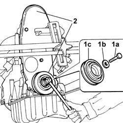
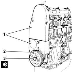
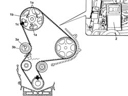
1. Undo bolt (1a) and remomve washer (1b) and accessory drivebelt pulley (1c).2. Remove both toothed timing belt covers.
Engines: 2.0 16V
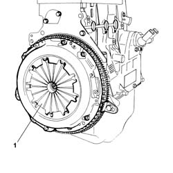
1. Unscrew the bolts and remove the clutch assembly.
Engines: 2.0 16V
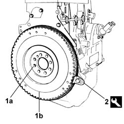
1. Undo retaining bolts (1a) and remove flywheel (1b).2. Remove the tool.
Description
Code
Function
2
Counter-torque
1.860.161.001
Tool for preventing crankshaft rotation
Engines: 2.0 16V
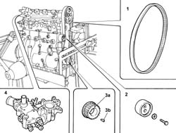
1. Loosen the tensioner roller retaining screw and remove the toothed belt.2. Remove the tensioner roller.3. Remove timing pinion (3a) and tab (2b).4. Remove the coil mount with thermostat.
Engines: 2.0 16V
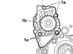
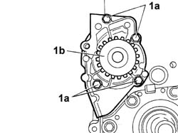
1. Undo bolts (1a) and remove coolant pump (1b).
Engines: 2.0 16V
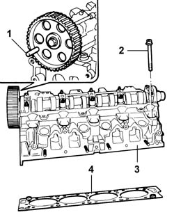
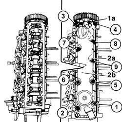
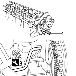
1. Turn the camshaft until the gear-cylinder head locating holes are aligned and introduce the 10 mm diameter reference pin.2. Unscrew the ten cylinder head retaining bolts.3. Remove the cylinder head.4. Remove the cylinder head gasket.- Remove the locating pins from the engine block.
Engines: 2.0 16V
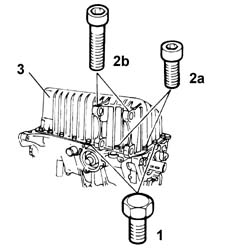
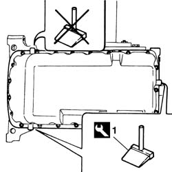
- Rotate the crankcase through 180° on the overhaul stand.1. Loosen the hex-heated retaining bolts.2. Unscrew the short (2a) and long (2b) hex-heated socket bolts.3. Remove the oil sump.
Engines: 2.0 16V
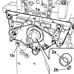
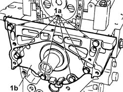
1. Undo the bolts (1a) and remove the engine block front cover (1b).2. Remove spacer (2a) with key (2b).
Engines: 2.0 16V
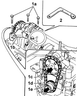
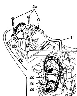
1. Undo bolts (1a) and remove oil pump (1b) complete with chain (1c), pinion (1d) and tab (1e).2. Remove the spacer washer.
Engines: 2.0 16V
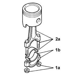
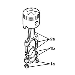
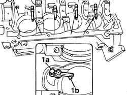
1. Undo the nuts (1a) and remove the connecting rod caps (1b) with bearing.2. Remove the piston-connecting rod-bolt-bearing assembly (2a) by withdrawing from below.- Repeat the same operation for all pistons.
Engines: 2.0 16V
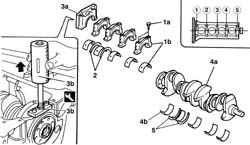
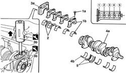
1. Undo bolts (1a) and remove the connecting rod caps (1b) with bearings, except for no.1.2. Remove the lower thrust washers (2a).3. Remove cap no. 1 (3a) using tools (3b), as described.
Description
Code
Function
3b
Extractor
1.860.854.000
Removing rear bearing cap
Description
Code
Function
3b
Mallet
1.846.011.000
Removing rear bearing cap
4. Remove crankshaft (4a) with bearings (4b)5. Remove the upper thrust washers.
Engines: 2.0 16V
1. Undo the oil duct sealing plugs.2. Remove the oil pressure sensor.3. Remove the water/oil sealing plugs from the engine block using a mallet.4. Remove the cover plate.
Engines: 2.0 16V
- Remove any damaged or broken studs.- Undo the bolts and remove the crankcase from the mounting brackets, then place it on a special workbench.
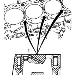
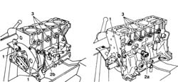
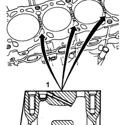
- Wash the dismantled components.- Clean all parts very thoroughly before refitting.- Clean the oil sump support surface thoroughly1. Clean the coolant ducts between the cylinders thoroughly using a steel scourer.
Engines: 2.0 16V
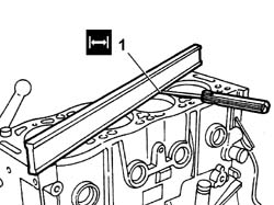
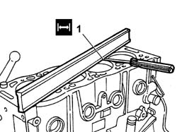
- Lubricate all the mechanical components with engine oil.- Check that the cylinder head support surface does not have cracks or superficial grooves.1. Check that the flatness of the cylinder head plane corresponds to the recommended values.
Subject
Value
1
CRANKCASE AND COMPONENTS
mm
-
Cylinder head support surface flatness
0,03
Engines: 2.0 16V
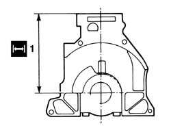
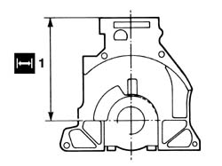
- Check that engine block height is within the recommended limits.
Subject
Value
1
CRANKCASE AND COMPONENTS
mm
-
Engine block height
234,95 - 235,05
Engines: 2.0 16V
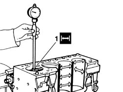
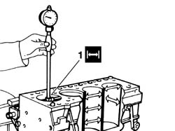
- If engine block flatness and/or height are not within specified limits, grind the cylinder head support surface.1. Measure the cylinder bore/liner diameter.
Subject
Value
1
CRANKCASE AND COMPONENTS
mm
-
Cylinder liner bore
86,000 - 86,018
- If the cylinder bore measurements are not within the recommended limits, ream the cylinder bores following the recommended oversizes.
Subject
Value
CRANKCASE AND COMPONENTS
mm
-
1st cylinder liner oversize
0,25
Subject
Value
.
CRANKCASE AND COMPONENTS
mm
-
2nd cylinder liner oversize
0,60
Engines: 2.0 16V
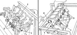
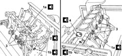
1. Fit oil duct plugs (1a) and (1b) and tighten to the specified torque.
Value - daNm
Fastening
Component
Ø
1a
2,5
Plug
CRANKCASE AND COMPONENTS
-
Value - daNm
Fastening
Component
Ø
1b
3,5
Plug
CRANKCASE AND COMPONENTS
-
Value - daNm
Fastening
Component
Ø
1b
2,5
Plug
CRANKCASE AND COMPONENTS
-
2. Fit the engine oil pressure sensor and tighten it to the recommended torque.
Value - daNm
Fastening
Component
Ø
2
6,0
Oil pressure sensor
CRANKCASE AND COMPONENTS
-
3. Fit the water sealing plugs in the crankcase using suitable fitting tools.4. Fit the cover plate on the engine block and tighten the bolts to the specified torque.
Value - daNm
Fastening
Component
Ø
4
0,5
Bolts
CRANKCASE AND COMPONENTS
Engines: 2.0 16V
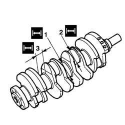
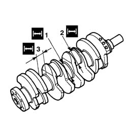
- Check that there are no deposits or blockages in the crankshaft lubrication ducts.- Check the static balance of the crankshaft resting the main journals on suitable parallels.1. Check that the diameter of the main journals is within specified limits.
Subject
Value
1
CRANKSHAFT
mm
-
Main journal diameter
59,975 - 60,000
- If the diameter of the main journals is not correct, they should be reground to the recommended undersize.
Subject
Value
.
CRANKSHAFT
mm
-
Main journal undersize
0,300
2. Check that the diameter of the crankpins is within specified limits.
Subject
Value
2
CRANKSHAFT
mm
-
Crankpin diameter
49,984 - 50,000
- If the diameter of the crankpins is not correct, they should be reground to the recommended undersize.
Subject
Value
.
CRANKSHAFT
mm
-
Crankpin undersize
0,300
3. Check that the width of main bearing no. 2 is within specified limits.
Subject
Value
3
CRANKSHAFT
mm
-
Width of main bearing no. 2
25,70 - 25,75
- If the width of main bearing no. 2 is not correct, it should be reground to the recommended undersize.
Subject
Value
.
CRANKSHAFT
mm
-
1st oversize on width of main journal bearing no. 2
0,20
-
2nd oversize on width of main journal bearing no. 2
0,30
-
3rd oversize on width of main journal bearing no. 2
0,40
Engines: 2.0 16V
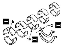
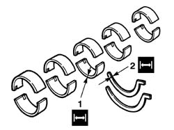
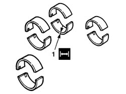
- If the crankshaft has been ground, fit new oversize bearings to restore the original clearance.- Check main bearing half condition by sight and replace if necessary. Do not attempt to adjust bearings.1. Check that the thickness of lower (1a) and upper (1b) half-bearings corresponds to specified limits; if not, replace them.
Subject
Value
1a
Lower main bearing half thickness
mm
-
Category A
1,844
-
Category B
1,857
Subject
Value
1a
Lower main bearing half thickness
mm
-
Category C
1,866
-
Category D
1,877
Subject
Value
1b
MAIN BEARINGS
mm
-
Upper main bearing half thickness
1,847
- If the crankshaft has been ground, fit new oversize bearings to restore the original clearance as described below.
Subject
Value
.
MAIN BEARINGS
-
Oversize lower main bearing half thickness
mm
-
Category A
1,994
-
Category B
2,007
Subject
Value
.
MAIN BEARINGS
-
Oversize lower main bearing half thickness
mm
-
Category C
2,016
-
Category D
2,027
Subject
Value
.
MAIN BEARINGS
mm
-
Oversize upper main bearing half thickness
1,997
2. Check that the thickness of the thrust half-rings corresponds to specified limits; if not, replace them.
Subject
Value
2
MAIN BEARINGS
mm
-
Thrust half-ring thickness
1,850
Engines: 2.0 16V
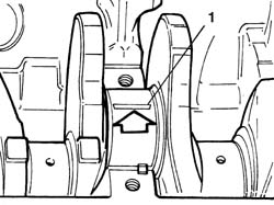
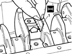
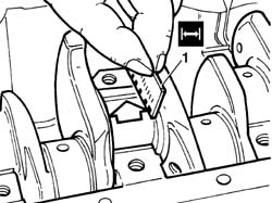
- Fit the upper main journal half-bearings in the cylinder block/crankcase.- Fit the crankshaft.1. Fit the calibrated wire (plastigate) for measuring the bearing clearance.
Engines: 2.0 16V
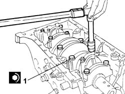
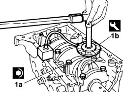
- Fit the main journal caps complete with half-bearings.1. Tighten the main bearing caps to the specified torque.
Value - daNm
Fastening
Component
Ø
1
7,0
Bolt
MAIN BEARINGS
-
Engines: 2.0 16V
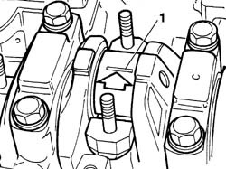
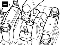
1. Remove the main bearing caps and the half-bearings and measure the journal clearance using the special graduated gauge.
Subject
Value
1
MAIN BEARINGS
mm
-
Radial clearance
0,039 - 0,080
- Choose the bearing category lower than the measured clerance to obtain the specified operating clearance of 0.038 - 0.069 mm.
Subject
Value
.
MAIN BEARINGS
-
Lower main bearing halves
mm
-
Category A
0,039 - 0,052
-
Category B
0,053 - 0,062
Subject
Value
.
MAIN BEARINGS
-
Lower main bearing halves
mm
-
Category C
0,063 - 0,074
-
Category D
0,075 - 0,080
Engines: 2.0 16V
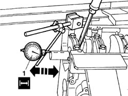
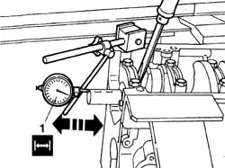
1. Refit the main bearing caps as described previously and check that the crankshaft end float is within specified limits using a magnetic base with dial gauge.
Subject
Value
1
CRANKSHAFT
mm
-
End float
0,032 - 0,007
- If the end float is not within specified limits, grind the crankshaft and fit new oversize thrust washers to restore the initial clearance.
Subject
Value
.
MAIN BEARINGS
mm
-
Thickness of thrust half-rings, 1st oversize
1,95
-
Thickness of thrust half-rings, 2nd oversize
2,00
-
Thickness of thrust half-rings, 3rd oversize
2,05
Engines: 2.0 16V
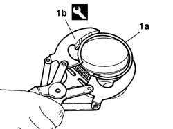
- Remove the rings (1a) from the pistons using tool (1b).
Description
Code
Function
1b
Extractor/Fitting tool
1.860.183.000
Extracting/fitting piston circlips
Engines: 2.0 16V
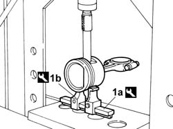
1. Remove the pin on a press using tools (1a) and (1b) and an appropriate pusher.
Description
Code
Function
1a
Brackets
1.840.005.108
Extracting gudgeon pin from piston
Description
Code
Function
1b
Base
1.840.005.311
Extracting gudgeon pin from piston
Engines: 2.0 16V
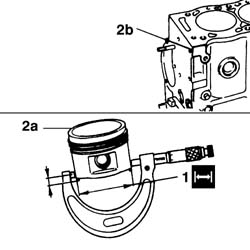
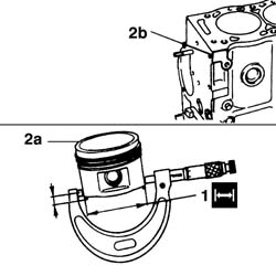
- Check the alignment of the connecting rods using suitable equipment; if it is not correct, replace the connecting rod.1. Check that the outer diameter of the pistons is within specified limits; if not, replace the piston complete with sealing rings and pin.
Subject
Value
1
ENGINE PISTON
mm
-
Outer diameter
85,958 - 85,976
-
Distance to lower piston edge
8
- If the cylinders have been reamed, fit pistons and new oversize rings to restore the original clearance.
Subject
Value
.
ENGINE PISTON
mm
-
1st oversize outer diameter
86,208 - 86,226
-
2nd oversize outer diameter
86,558 - 86,576
2. Mark any oversize on the piston crown (2a) and the base on the engine block (2b).
Engines: 2.0 16V
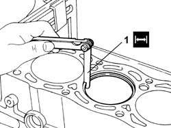
1. If the bore has to be reamed, fit the piston rings and the oil scraper ring in the cylinder bore and check that the gap between the end of each ring is within specified limits; if not, replace the piston rings.
Subject
Value
1
PISTON RING SET
mm
-
First ring gap
0,20 - 0,40
-
Second ring gap
0,15 - 0,35
Engines: 2.0 16V
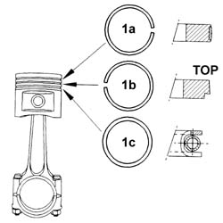
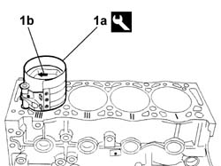
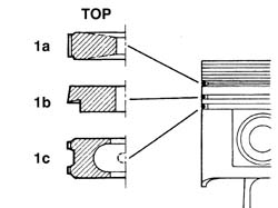
1. Fit sealing segments (1a) and (1b) and oil scaper ring (1c) on the pistons with the wording TOP facing uppermost.
Engines: 2.0 16V
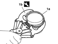
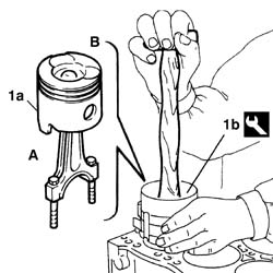
- Fit the piston rings using the tool.
Description
Code
Function
.
Extractor/Fitting tool
1.860.183.000
Extracting/fitting piston circlips
1. Heat the connecting rods to the specified temperature using a thermostatically-controlled oven.
Subject
Value
1
CONNECTING ROD ASSEMBLY
°C
-
Heating
230 - 250
Engines: 2.0 16V
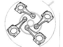
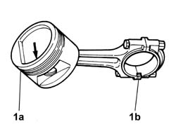
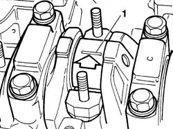
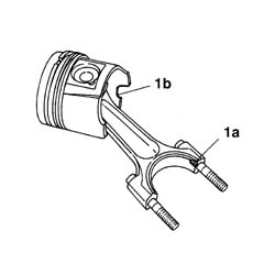
1. Position the piston in relation to the connecting rod so that arrow (1a) and bearing detent tooth (1b) are in the position shown.
Engines: 2.0 16V
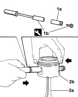
1. Fit piston pin ( 1a) to tool (1b) and lock using the threaded endpiece.
Description
Code
Function
1b
Fitting tool
1.860.275.000
Fitting gudgeon pin
2. Tighten connecting rod (2a) in a vice and position piston (2b) as specified.- Quickly push the pin fully home against the piston wall.- Repeat the same operation for all connecting rod - piston assemblies.
Engines: 2.0 16V
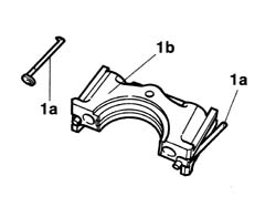
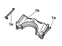
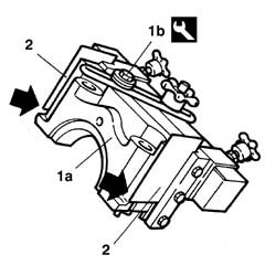
- Fit the upper main journal half-bearings in the cylinder block/crankcase.- Fit the crankshaft.1. Fit both side gaskets (1a) into the cap seats (1b).
Engines: 2.0 16V
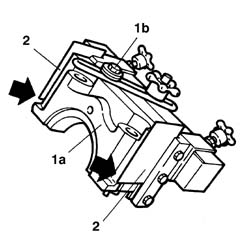
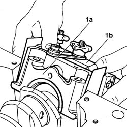
1. Position tool (1b) on cap (1a) complete with gaskets. Secure using a bolt;2. Ensure that the steel tabs fit over the step on the cap sides;
Description
Code
Function
1b
Fitting tool
1.860.808.000
Fitting rear bearing cap
Engines: 2.0 16V
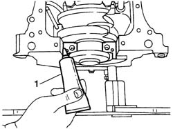
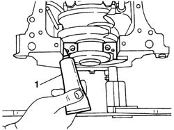
1. Arrange the sealant product on the cap-engine block mating surfaces and lubricate the engine block housing sides;
Description
Qty.
Component
Type
Classification
1
RECTI JOINT
-
MAIN BEARINGS
Silicone sealant
Engines: 2.0 16V
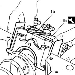
1. Fit cap (1a) initially tilted to about 45°, then straighten and carefully lower into the housing; tighten the bolts as described for the other main bearing caps and then withdraw tool (1b) horizontally.
Description
Code
Function
1b
Fitting tool
1.860.808.000
Fitting rear bearing cap
Engines: 2.0 16V
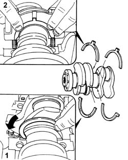
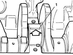
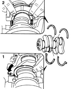
1. Fit the upper half-rings: turn the grooved part of the half-ring toward the crankshaft.2. Fit main bearing cap no. 2, fitted in turn with both lower half-rings positioned in the same way.
Engines: 2.0 16V
- Fit main bearing caps 3, 4 and 5 with bearing halves.- Tighten the main bearing caps to the specified torque.
Value - daNm
Fastening
Component
Ø
.
7,0
Bolt
MAIN BEARINGS
-
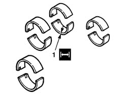
- Check connecting rod bearing half condition by sight and replace if necessary. Do not attempt to adjust bearings.1. Check that the thickness of the connecting rod half-bearings is within specified limits; if not, replace them.
Subject
Value
1
BIG END BEARINGS
mm
-
Connecting rod bearing half thickness
1,832 - 1,842
- If the crankshaft has been ground, fit new oversize bearings to restore the original clearance.
Subject
Value
.
BIG END BEARINGS
mm
-
Oversize connecting rod bearing half thickness
1,982 - 1,992
Engines: 2.0 16V
- Rotate the crankshaft until the cylinder concerned is at B.D.C.1. Use tool (1a) to fit the piston-connecting rod assemblyl so that arrow (1b) stamped on the piston crown faces the timing side.
Description
Code
Function
1a
Fitting tool
1.860.700.000
Fitting tool
- Repeat the procedure for all connecting rod-piston assemblies.
Engines: 2.0 16V
- Fit the upper connecting rod half-bearings on the big end.1. Fit the calibrated wire (plastigate) for measuring the bearing clearance.
Engines: 2.0 16V
- Fit the connecting rod caps complete with lower half-bearings.- Tighten the connecting rod caps to the specified torque.
Value - daNm
Fastening
Component
Ø
.
4,0
Bolt
BIG END BEARINGS
-
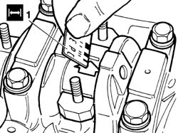
1. Remove the connecting rod cap and the half-bearing and measure the bearing clearance using the special gauge.
Engines: 2.0 16V
- Pretighten the connecting rod caps to the specified torque.
Value - daNm
Fastening
Component
Ø
.
4,0
Bolt
BIG END BEARINGS
-
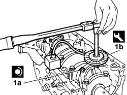
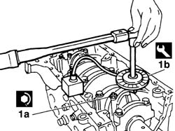
- Loosen all the connecting rod cap bolts.1. Tighten connecting rod caps (1a) to the specified torque using an Usag tool or similar commercial tool (1b) for angle tightening.
Value - daNm
Fastening
Component
Ø
1a
2,0 + 70°
Bolt
BIG END BEARINGS
-
Engines: 2.0 16V
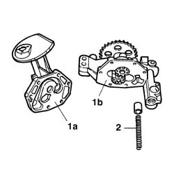
1. Remove cover (1a) from oil pump casing (1b) by unscrewing the retaining bolts.2. Carefully take off the cover with oil pressure regulation valve spring.
Engines: 2.0 16V
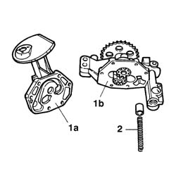
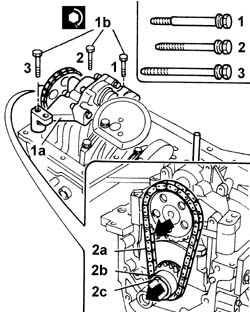
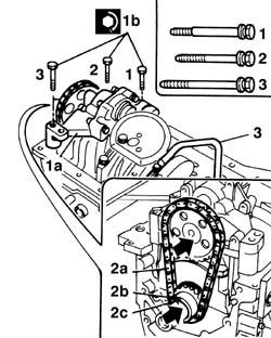
- Check component condition.- Use a feeler gauge to check that the clearance between teeth and pump casing is not excessive.- Re-assemble the pump, ensuring that the spring and pressure regulation valve are correctly positioned;- Fit the spacer washer to the engine block.1. Fit oil pump (1a) and tighten bolts (1b) to the specified torque:
Value - daNm
Fastening
Component
Ø
1b
1,6
Bolt
ENGINE OIL PUMP
-
2. Fit chain (2a), pinion (2b) and tab (2c).
Engines: 2.0 16V
- Apply sealanta to the engine block front cover contact surfaces.
Description
Qty.
Component
Type
Classification
.
Dow Corning 7091
-
OIL SUMP
Silicone sealant
-
- Fit the cover and tighten the bolts to the recommended torque.
Value - daNm
Fastening
Component
Ø
.
15,0
Bolt
FRONT COVER CRANKSHAFT
-
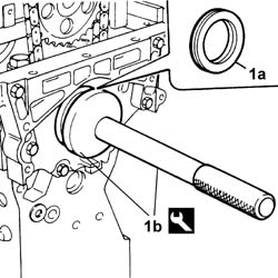
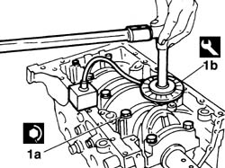
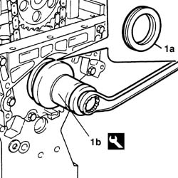
1. Fit sealing ring (1a) using tools (1b).
Description
Code
Function
1b
Fitting tool
1.860.672.000
Fitting crankshaft front oil seal
Description
Code
Function
1b
Grip
1.870.007.000
Camshaft front oil seal fitting
Engines: 2.0 16V
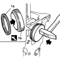
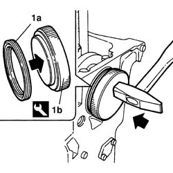
- Fit sealing ring (1a) using tools(1b).
Description
Code
Function
1b
Fitting tool
1.860.806.000
Fitting crankshaft rear oil seal
Engines: 2.0 16V
- Apply sealant to the engine block front cover contact surfaces.
Description
Qty.
Component
Type
Classification
.
Dow Corning 7091
-
OIL SUMP
Silicone sealant
-
1. Fit the crankcase sump.2. Tighten hex-headed bolts, short hex-headed socket bolts (2b) and long hex-headed socket bolts (2c) in the position shown.
Engines: 2.0 16V
1. Fit the tool.
Description
Code
Function
1
Counter-torque
1.860.161.001
Tool for preventing crankshaft rotation
2. Fit the flywheel and centre the reference dowl.3. Tighten the retaining bolts to the recommended torque.
Value - daNm
Fastening
Component
Ø
3
5
Bolt
FLYWHEEL (MECH.)
-
Engines: 2.0 16V
- Remove the tool.
Description
Code
Function
.
Counter-torque
1.860.161.001
Tool for preventing crankshaft rotation
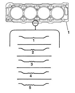
1. Select the cylinder head gasket to be used.
Subject
Value
1a
CYLINDER HEAD GASKET
mm
-
Size
1,30
-
Ground cylinder head
-
Subject
Value
1b
CYLINDER HEAD GASKET
mm
-
Size
1,50
-
Ground cylinder head
-
Engines: 2.0 16V
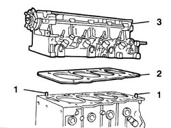
1. Position the cylinder head locating bushes on the cylinder block.2. Position the cylinder head gasket on the cylinder block/crankcase.3. Position the cylinder head.
Engines: 2.0 16V
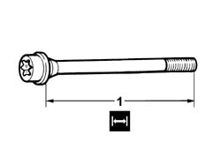
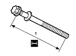
1. Check that retaining bolt length does not exceed the specified value: otherwise replace.
Subject
Value
1
CYLINDER HEAD RETAINING ELEMENTS
mm
-
Retaining bolt length
122,0
Engines: 2.0 16V
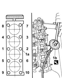
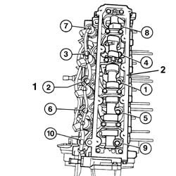
- Lubricate the bolt thread and contact surface.1. Tighten the cylinder head bolts (1a) to the recommended torque in the order indicated, using an Usag angular tightening tool (1b) or similar commercial tool.
Value - daNm
Fastening
Component
Ø
1a
3,5 + 7,0 + 160°
Bolt
CYLINDER HEAD
-
Engines: 2.0 16V
- Apply sealant to the engine coolant pump contact surfaces.
Description
Qty.
Component
Type
Classification
.
Dow Corning 7091
-
OIL SUMP
Silicone sealant
-
- Fit the coolant pump and tighten the bolts to the specified torque.
Value - daNm
Fastening
Component
Ø
.
1,2
Bolt
COOLANT PUMP
-
- Apply sealant to the coil mount contact surfaces.
Description
Qty.
Component
Type
Classification
.
DOW CORNING 7091
-
THERMOSTAT MOUNT
Silicone sealant
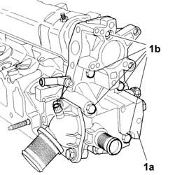
1. Fit coil mount (1a) complete with thermostat and coolant pump connection pipe and tighten retaining bolts (1b) to the specied torque.
Value - daNm
Fastening
Component
Ø
.
1,6
Bolt
THERMOSTAT MOUNT
-
Engines: 2.0 16V
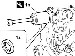
1. Fit sealing ring (1a) using tool (1b).
Description
Code
Function
1b
Fitting tool
1.860.807.000
Camshaft front oil seal fitting
Engines: 2.0 16V
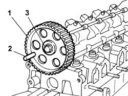
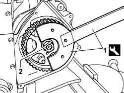
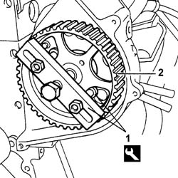
1. Fit the camshaft gear, taking care to engage the reference on the shaft with the groove on the pulley.2. Turn the camshaft until the gear-cylinder head locating holes are aligned and introduce the 10 mm diameter reference pin.3. Tighten the gear retaining bolt to the recommended torque.
Value - daNm
Fastening
Component
Ø
3
4,5
Bolt
TIMING DRIVEN PULLIES
-
Engines: 2.0 16V
1. Fit both tabs (1a) and spacer (1b).
Engines: 2.0 16V
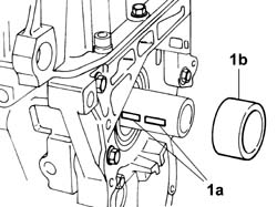
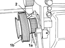
1. Fit timing pinion (1a), accessory drivebelt pulley (1b) and screw in the retaining bolt without tightening.2. Turn the crankshaft until the pulley-engine block locating holes are aligned and introduce the 8 mm diameter reference pin.
Engines: 2.0 16V
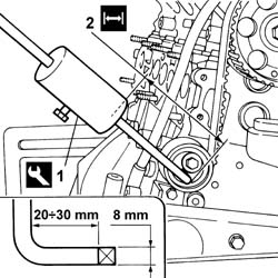
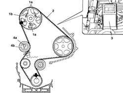
- Fit the mobile tensioner at the lowest tension.- Fit the timing belt over the gear, pinion, water pump and tensioner respectively.- Remove 8 mm diameter pin from the accessory drivebelt pulley and the 10 mm diameter pin from the timing gear.- Rotate the crankshaft throught two full revolutions in the direction of rotation without turning backwards.- Check the timing adjustment is correct by repositioning the engine so that both reference pins can be introduced.- Otherwise remove the timing belt and repeat the procedure.- Remove the accessory drivebelt pulley.1. Fit the square cross-section end into the mobile tensioner groove.
Description
Code
Function
1
Tool
1.860.755.000
Timing belt tensioning
2. Adjust mass position so that it is at the specified distance from the groove centreline.
Subject
Value
2
TOOTHED TIMING BELT
mm
-
Mass position
30
Engines: 2.0 16V
- Rotate the crankshaft throught two full revolutions in the direction of rotation without turning backwards.- Tighten the tensioner bolt to the recommended torque.
Value - daNm
Fastening
Component
Ø
.
2,1
Bolt
MOBILE TIMING TENSIONER
-
- Remove the tool.
Description
Code
Function
.
Tool
1.860.755.000
Timing belt tensioning
- Fit the cylinder head gasket and cover and tighten the ten bolts to the specified torque.
Value - daNm
Fastening
Component
Ø
.
1,0
Bolt
CAM COVER
-
- Fit the flywheel locking tool.
Description
Code
Function
.
Counter-torque
1.860.161.001
Tool for preventing crankshaft rotation
1. Fit the lower and upper timing belt cover and tighten the retaining bolts.2. Fit the accessory drivebelt pulley, washer and retaining bolt.3. Tighten the retaining bolt to the specified torque.
Value - daNm
Fastening
Component
Ø
3
4,0 + 51°
Bolt
CRANKSHAFT PULLEY
-
Engines: 2.0 16V
- Fit the clutch assembly and tighten the bolts to the recommended torque.
Value - daNm
Fastening
Component
Ø
.
1,3
Bolt
CLUTCH ASSEMBLY
-
- Remove the tool.
Description
Code
Function
.
Counter-torque
1.860.161.001
Tool for preventing crankshaft rotation
1. Fit the oil dipstick, applying sealant to the contact edge and tighten the bolt.
Description
Qty.
Component
Type
Classification
1
DOW CORNING 7091
-
OIL LEVEL DIPSTICK TUBE SEAL
Silicone sealant
Engines: 2.0 16V
1. Fit a new oil filter.2. Remove the oil vapour separator complete with pipes.3. Fit the intake manifold complete with throttle body and fuel manifold with a set of new gaskets and tighten the retaining bolts to the specified torque.
Value - daNm
Fastening
Component
Ø
.
1,9
Bolt
INLET MANIFOLD
-
Engines: 2.0 16V
1. Fit the coolant manifold with a new gasket and tighten the bolts to the recommended torque.
Value - daNm
Fastening
Component
Ø
.
2,0
Bolt
ENGINE FLUID INTAKE FITTING
-
2. Fit the exhaust manifold with a set of new gaskets and tighten the nuts to the recommended torque.
Value - daNm
Fastening
Component
Ø
.
3,5
Nut
EXHAUST MANIFOLD/S
-
3. Fit the exhaust manifold heat shield.4. Fit the ignition coil.5. Fit the engine mounting brackets.
Engines: 2.0 16V
- Fit the spark plug leads and brackets. See in Op. 1004D40
Air conditioning compressor engagement electro-magnet
L020
Description
Connector
.
Injection pump third piston deactivation solenoid valve
L005
Description
Connector
.
Fuel pressure regulator
N077
Description
Connector
.
Engine coolant temperature sensor/sender unit
K036
Description
Connector
.
Heater plugs
A040B
Description
Connector
.
Heater plugs
A040C
Description
Connector
.
Heater plugs
A040D
Description
Connector
.
Fuel pressure sensor
K083
Description
Connector
.
Engine oil pressure sensor
K028
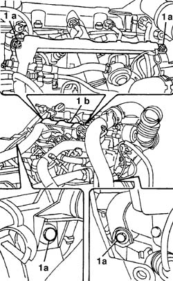
1. Undo bolts (1a), release from the bands and remove duct (1b) with wiring.
Engines: 2.0 JTD 8V
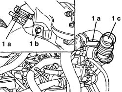
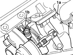
- Remove the pneumatic connection pipe from the EGR valve and wastegate.1. Remove oil vapour intake pipe (1a), undo bolt (1b), remove the turbocharger connection bands and remove intake sleeve (1d).
Engines: 2.0 JTD 8V
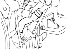
1. Remove the engine oil return pipe from the turbo.
Engines: 2.0 JTD 8V
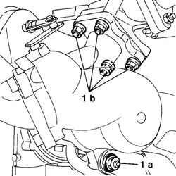
1. Undo lower mount nut (1a) and the four flange nuts (1b) while supporting the turbocharger.
Engines: 2.0 JTD 8V
1. Lower turbocharger (1a), undo oil delivery connector (1b) and remove the turbocharger assembly.
Engines: 2.0 JTD 8V
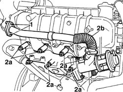
1. Undo the bolts securing the EGR pipe.2. Undo bolts (2a) and remove exhaust manifold (2b) complete with EGR valve and pipe, spacers and gaskets.
Engines: 2.0 JTD 8V
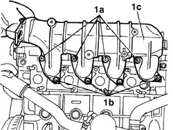
1. Undo bolts (1a) and nuts (1b) and remove intake manifold (1c) complete with plastic sleeve and gaskets.
Engines: 2.0 JTD 8V
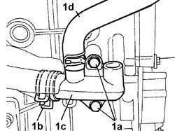
1. Unscrew bolts (1a), remove band (1b) connecting the thermostat pipe and remove the rigid coolant intake pipe to pump (1c) complete with flexible hose (1d).
Engines: 2.0 JTD 8V
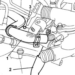
1. Disconnect the heat exchanger pipe from the thermostat.2. Disconnect the supplementary heater pipe from the thermostat.3. Undo the oil dipstick tube retaining bolt.
Engines: 2.0 JTD 8V
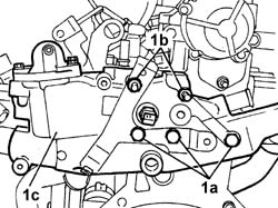
1. Undo bolts (1a) and nuts (1b) and remove thermostat (1c) complete with coolant connection pipe.
Engines: 2.0 JTD 8V
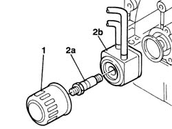
1. Remove the oil filter.2. Undo bolt (2a) and remove oil-water exchanger (2b) complete with gasket.
Engines: 2.0 JTD 8V
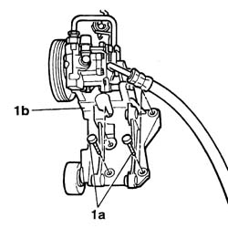
1. Undo bolts (1a) and remove power steering mount (1b) with pump and pipe.
Engines: 2.0 JTD 8V
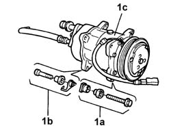
1. Undo front bolt (1a) and rear bolt (1b) and remove compressor (1c), recovering the profiled shims and nuts.
Engines: 2.0 JTD 8V
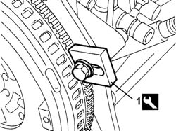
- Unscrew the retaining bolts and remove both cable and pipe brackets.1. Fit the tool.
Description
Code
Function
1
Counter-torque
1.860.846.000
Flywheel lock
Engines: 2.0 JTD 8V
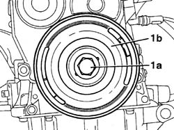
1. Unscrew bolt (1a) and remove auxiliary driveblet pulley (1b).
Engines: 2.0 JTD 8V
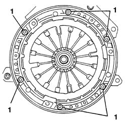
1. Unscrew the bolts and remove the clutch assembly.
Engines: 2.0 JTD 8V
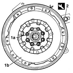
1. Undo the eight bolts (1a) and remove engine flywheel (1b).2. Remove the tool.
Description
Code
Function
2
Counter-torque
1.860.846.000
Flywheel lock
Engines: 2.0 JTD 8V
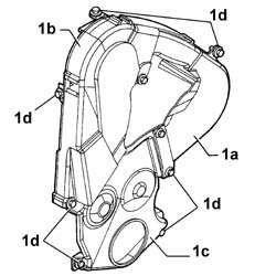
1. Remove timing belt front cover (1a), upper cover (1b) and lower cover (1c) in order by unscrewing retaining bolts (1d).
Engines: 2.0 JTD 8V
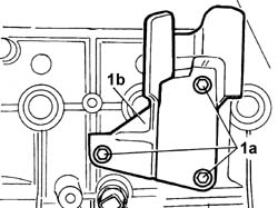
1. Undo bolts (1a) and remove the timing side engine support (1b).
Engines: 2.0 JTD 8V
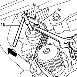
1. Loosen bolt (1a) and use a ¼" box wrench (1b) to loosen the belt, then tighten the bolt again and remove timing belt (1c).
Engines: 2.0 JTD 8V
- Disconnect the vapour recirculation pipe from the cylinder head cover.1. Undo bolt (1a) and remove the fuel temperature sensor (1b).
Engines: 2.0 JTD 8V
1. Fit the tools.
Description
Code
Function
1
Counter-torque
1.860.831.000
Timing pulley lock
Description
Code
Function
1
Counter-torque
1.860.831.001
Timing pulley lock
2. Undo the pulley bolt.
Engines: 2.0 JTD 8V
1. Fit the tools.
Description
Code
Function
1
Extractor
1.860.954.001
Pressure pump control pulley removal
Description
Code
Function
1
Reaction pins
1.860.954.002
Pressure pump control pulley removal
2. Remove the pulley.
Engines: 2.0 JTD 8V
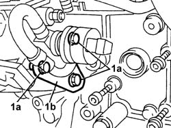
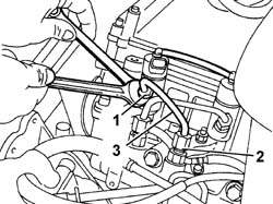
1. Use a wrench and counterwrench to loosen the pump side high pressure pipe connector.2. Loosen the manifold side high pressure pipe connector (2a) and remove pipe (2b).
Engines: 2.0 JTD 8V
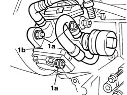
1. Undo the bolts (1a) and remove the rear bracket (1b).
Engines: 2.0 JTD 8V
1. Undo nuts (1a) and remove high pressure pump (1b).
Engines: 2.0 JTD 8V
1. Use a wrench and counterwrench to loosen the injector side high pressure pipe connector.2. Loosen the fuel manifold side high pressure pipe connector.3. Remove the pipe.
Engines: 2.0 JTD 8V
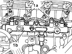
- Repeat the operations for all injectors.1. Undo bolts (1a) and remove manifold (1b).
Engines: 2.0 JTD 8V
1. Undo bolts (1a) and remove the high pressure pump mount (1b).
Engines: 2.0 JTD 8V
1. Undo bolts (1a) and remove the fuel filter mount (1b).
Engines: 2.0 JTD 8V
1. Undo bolt (1a) and remove the oil dipstick (1b).
Engines: 2.0 JTD 8V
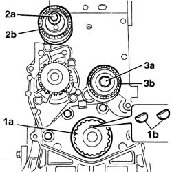
- Remove the coolant pipes from the engine block.1. Remove the timing belt pulley (1a) and recover both tabs (1b).2. Undo bolt (2a) and remove the timing belt mobile tensioner (2b).3. Undo bolt (3a) and remove the fixed timing belt mobile tensioner (2b).
Engines: 2.0 JTD 8V
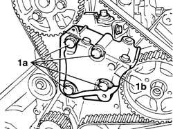
1. Undo the bolts (1a) and remove the coolant pump (1b).
Engines: 2.0 JTD 8V
1. Undo the retaining bolt and remove the engine timing sensor.2. Undo the ten bolts (2a) and remove the cylinder head cover (2b).- Undo the bolts in the order indicated.
Engines: 2.0 JTD 8V
1. Undo the retaining bolts.- Undo the bolts in the order indicated.2. Remove the cylinder head.- Remove the cylinder head gasket.- Remove the locating pins.
Engines: 2.0 JTD 8V
- Rotate the crankcase through 180° on the overhaul stand.1. Unscrew the retaining bolts and remove the oil sump using the tool at the points indicated.
Description
Code
Function
.
Blade
1.870.718.000
Engine oil sump removal
Engines: 2.0 JTD 8V
1. Undo bolts (1a) and remove the engine block front cover (1b).
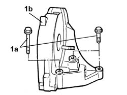
Engines: 2.0 JTD 8V
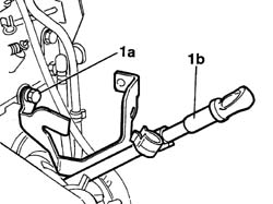
1. Undo bolt (1a) and remove the engine oil dipstick tube.2. Undo bolts (2a) and remove oil pump (2b) complete with chain (2c), pinion (2d) and tab (2e).
Engines: 2.0 JTD 8V
1. Undo nuts (1a) and remove the connecting rod caps (1b) with bearing.2. Remove the piston-connecting rod-bolt-bearing assembly by withdrawing from below.- Repeat the operations for all pistons.
Engines: 2.0 JTD 8V
1. Undo bolts (1a) and remove the main bearing caps (1b) with bearings, except no. 1.2. Remove the lower thrust rings.3. Remove cap no. 1 (3a) using tools (3b) as shown.
Description
Code
Function
3a
Extractor
1.860.854.000
Removing rear bearing cap
Description
Code
Function
3a
Mallet
1.846.011.000
Removing rear bearing cap
4. Remove crankshaft (4a) complete with bearings (4b).5. Remove the upper thrust rings.
Engines: 2.0 JTD 8V
1. Undo the bolt (1a) and remove the oil sprays (1b).
Engines: 2.0 JTD 8V
- Rotate the crankcase through 180° on the overhaul stand.1. Unscrew the oil channel sealing plugs.2. Remove oil pressure sensor (2a) and oil temperature sensor (2b).3. Remove the water sealing plugs from the engine block using a drift.
Engines: 2.0 JTD 8V
- Remove any damaged or broken studs.- Undo the bolts and remove the crankcase from the mounting brackets, then place it on a special workbench.
- Wash the dismantled components.- Clean all parts very thoroughly before installing.- Clean the oil sump contact surface thoroughly.1. Clean the coolant channels between the cylinders thoroughly using a steel scourer.
Engines: 2.0 JTD 8V
- Lubricate all the mechanical components with engine oil.- Check that the cylinder head support surface does not have cracks or superficial grooves.1. - Check that cylinder head support surface flatness is within specified limits.
Subject
Value
1
CRANKCASE AND COMPONENTS
mm
-
Cylinder head support surface flatness
0,03
Engines: 2.0 JTD 8V
1. Check that crankcase height is within specified limits.
Subject
Value
1
CRANKCASE AND COMPONENTS
mm
-
Engine block height
234,95 - 235,05
- If engine block flatness and/or height are not within specified limits, grind the cylinder head support surface without exceeding the minimum permitted height.
Subject
Value
.
CRANKCASE AND COMPONENTS
mm
-
Minimum permitted crankcase height
234,75 - 234,85
Engines: 2.0 JTD 8V
1. Measure the cylinder bore/liner diameter.
Subject
Value
1
CRANKCASE AND COMPONENTS
mm
-
Cylinder liner bore
85,000 - 85,018
- Check that the taper of the cylinder liners/bores is within the recommended limits.
Subject
Value
.
CRANKCASE AND COMPONENTS
mm
-
Cylinder liner taper
< 0,009
- Check that the straightness of the cylinder liners/bores is within the recommended limits.
Subject
Value
.
CRANKCASE AND COMPONENTS
mm
-
Cylinder liner straightness
< 0,0055
- If the cylinder bore measurements are not within the recommended limits, ream the cylinder bores following the recommended oversizes.
Subject
Value
.
CRANKCASE AND COMPONENTS
mm
-
Cylinder liner oversize
0,60
Engines: 2.0 JTD 8V
1. Fit oil sprays (1b), tighening bolt (1a) to the specified torque.
Value - daNm
Fastening
Component
Ø
1a
1,0
Bolt
PISTON COOLING NOZZLES
-
Engines: 2.0 JTD 8V
1. Fit the oil channel plugs, tightening to the specified torque.
Value - daNm
Fastening
Component
Ø
1
4,0
Plug
CRANKCASE AND COMPONENTS
-
2. Fit oil pressure sensor (2a) and oil level sensor (2b) and tighten to the specified torque.
Value - daNm
Fastening
Component
Ø
2a
3,0
Oil pressure sensor
CRANKCASE AND COMPONENTS
-
Value - daNm
Fastening
Component
Ø
2b
2,7
Oil level sensor
CRANKCASE AND COMPONENTS
-
3. Fit the water sealing plugs in the crankcase using suitable fitting tools.
Engines: 2.0 JTD 8V
- Check that there are no deposits or blockages in the crankshaft lubrication ducts.- Check the static balance of the crankshaft resting the main journals on suitable parallels.1. Check that the diameter of the main journals is within specified limits.
Subject
Value
1
CRANKSHAFT
mm
-
Main journal diameter
59,977 - 60,000
- If the diameter of the main journals is not correct, they should be reground to the recommended undersize.
Subject
Value
.
CRANKSHAFT
mm
-
Main journal undersize
0,300
2. - Check that the diameter of the crankpins corresponds to the recommended figures.
Subject
Value
2
CRANKSHAFT
mm
-
Crankpin diameter
49,980 - 50,000
- If the diameter of the crankpins is not correct, they should be reground to the recommended undersize.
Subject
Value
.
CRANKSHAFT
mm
-
Main journal undersize
0,300
3. Check that the width of main bearing no. 2 is within specified limits.
Subject
Value
3
CRANKSHAFT
mm
-
Width of main bearing no. 2
26,630 - 26,650
- If the width of main bearing no.2 is not correct, it should be reground to the recommended undersize.
Subject
Value
.
CRANKSHAFT
mm
-
Oversize of main journal bearing no. 2
0,300
Engines: 2.0 JTD 8V
- Check the condition of the main bearing halves by sight and replace if necessary. Do not adjust bearings.1. Check that the thickness of the half-bearings corresponds to the recommended figures; if not, replace them.
Subject
Value
1
MAIN BEARINGS
mm
-
Main bearing half thickness
1,839 - 1,845
- If the crankshaft has been ground, fit new oversize bearings to restore the initial clearance.
Subject
Value
.
MAIN BEARINGS
mm
-
Oversize main bearing half thickness
1,989 - 1,995
2. Check that the thickness of the thrust half-rings corresponds to the recommended figures; if not, replace them.
Subject
Value
2
MAIN BEARINGS
mm
-
Thrust half-ring thickness
2,580 - 2,630
Engines: 2.0 JTD 8V
- Fit the upper main journal half-bearings in the cylinder block/crankcase.- Fit the crankshaft.1. Fit the calibrated wire (plastigate) for measuring the bearing clearance.
Engines: 2.0 JTD 8V
- Fit the main bearing caps complete with half-bearings.1. Tighten main bearing caps (1a) to the specified torque. Use USAG tool (1b) or similar for angular tightening.
Value - daNm
Fastening
Component
Ø
1a
2,5 + 60°
Bolt
MAIN BEARINGS
-
Engines: 2.0 JTD 8V
1. Remove the main bearing caps and the half-bearing and measure the journal backlash using the special graduated gauge.
Engines: 2.0 JTD 8V
1. Fit the main bearing caps as described previously and check that crankshaft end float is within specified limits using a magnetic base with dial gauge.
Subject
Value
1
CRANKSHAFT
mm
-
End float
0,032 - 0,008
Engines: 2.0 JTD 8V
- If the end float is not within specified limits, grind the crankshaft and fit new oversize thrust rings to restore the initial clearance.
Subject
Value
MAIN BEARINGS
mm
-
Oversize thrust half-ring thickness
2,730 - 2,780
1. Remove rings (1a) from the pistons using a suitable tool (1b).
Description
Code
Function
1b
Extractor/Fitting tool
1.860.183.000
Extracting/fitting piston circlips
Engines: 2.0 JTD 8V
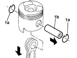
1. Remove piston rings (1a) from the grooves and withdraw pin (1b), separating the connecting rod from the piston.
Engines: 2.0 JTD 8V
- Check the alignment of the connecting rods using suitable equipment; if it is not correct, replace the connecting rod.- Check that the small end bush bore is within the recommended limits; if not, replace the connecting rod.
Subject
Value
.
SMALL END BUSH
mm
-
Inner diameter
28,020 - 28,027
- Check that the piston pin seat bore is within the recommended limits; if not, replace the piston.
Subject
Value
.
PISTON SET
mm
-
Piston pin seat bore
28,010 - 28,015
1. Measure the piston outer diameter.- If the cylinders have been reamed, fit new oversize pistons and rings to restore the initial clearance.
Subject
Value
.
ENGINE PISTON
mm
-
Outer diameter oversize
0,60
2. Mark any oversize on the piston crown (2a) and crankcase base (2b).
Engines: 2.0 JTD 8V
- If the bore has to be reamed, fit the piston rings and the oil scraper ring in the cylinder bore and check that the gap between the end of each ring corresponds to the recommended figures; if not, replace the piston rings.
Subject
Value
.
PISTON RING SET
mm
-
First ring gap
0,20 - 0,40
-
Second ring gap
0,15 - 0,35
1. Fit sealing segments (1a) and (1b) and oil scraper ring (1c) on the pistons with the wording TOP facing up.
Engines: 2.0 JTD 8V
- Fit the piston rings using the tool
Description
Code
Function
.
Extractor/Fitting tool
1.860.183.000
Extracting/fitting piston circlips
1. Join the connecting rods with the pistons so that the number stamped on the big end (1a) is facing opposite the reference (1b) on the piston.- Fit the pins and secure them using the circlips.
Engines: 2.0 JTD 8V
- Fit the upper main journal half-bearings in the cylinder block/crankcase.- Fit the crankshaft.1. Fit both flexible side gaskets (1a) into the cap seats (1b).
Engines: 2.0 JTD 8V
1. Position tool (1b) on cap (1a) complete with gaskets and secure using a bolt.2. Ensure the steel tabs fit over the step in the side of the cap.
Description
Code
Function
1b
Fitting tool
1.860.808.000
Fitting rear bearing cap
Engines: 2.0 JTD 8V
1. Spread sealant over the cap-crankcase mating surfaces and lubricate the sides of the crankcase housing.
Description
Qty.
Component
Type
Classification
1
RECTI JOINT
-
MAIN BEARINGS
Silicone sealant
Engines: 2.0 JTD 8V
1. Insert cap (1a) at an initial angle of 45° and then straighten before lowering into the housing. Tighten the bolts as described for the other main bearing caps and then withdraw the tool horizontally (1b).
Description
Code
Function
1b
Fitting tool
1.860.808.000
Fitting rear bearing cap
Engines: 2.0 JTD 8V
1. Fit the upper half-rings: the grooved side of the half-ring must be turned toward the crankshaft.2. Fit main bearing cap no. 2 with both lower half-rings in place and position as before.
Engines: 2.0 JTD 8V
- Fit main bearing caps 3, 4 and 4 complete with bearing halves.1. Tighten main bearing caps (1a) to the specified torque. Use USAG tool (1b) or similar for angular tightening.
Value - daNm
Fastening
Component
Ø
1a
2,5 + 60°
Bolt
MAIN BEARINGS
-
Engines: 2.0 JTD 8V
- Check the condition of the connecting rod bearing halves by sight and replace if necessary. Do not adjust bearings.1. Check that the thickness of the connecting rod half-bearings corresponds to the recommended figures; if not, replace them.
Subject
Value
1
BIG END BEARINGS
mm
-
Connecting rod bearing half thickness
1,827 - 1,838
- If the crankshaft has been ground, fit new oversize bearings to restore the initial clearance.
Subject
Value
.
BIG END BEARINGS
mm
-
Oversize connecting rod bearing half thickness
1,978 - 1,992
Engines: 2.0 JTD 8V
- Rotate the crankshaft until the cylinder concerned is at B.D.C.1. Fit the piston-connecting rod assembly (1a) using the tool (1b).
Description
Code
Function
1b
Fitting tool
1.860.700.000
Piston ring fitting
- Repeat the procedure for all connecting rod - piston sets.
Engines: 2.0 JTD 8V
- Fit the upper connecting rod half-bearings on the big end.1. Fit the calibrated wire (plastigate) for measuring the bearing clearance.
Engines: 2.0 JTD 8V
- Fit the connecting rod caps complete with lower half-bearings.1. Tighten main bearing caps (1a) to the specified torque. Use USAG tool (1b) or similar for angular tightening.
Value - daNm
Fastening
Component
Ø
1a
2,1 + 74°
Bolt
BIG END BEARINGS
-
Engines: 2.0 JTD 8V
1. Remove the connecting rod cap and the half-bearing and measure the bearing clearance using the special gauge.
Engines: 2.0 JTD 8V
- Tighten the connecting rod caps finally as described previously.1. Remove cover (1a) from oil pump case (1b) by unscrewing the retaining bolts.2. Carefully take off the cover complete with oil pressure regulation valve spring.
Engines: 2.0 JTD 8V
- Check the condition of the components.- Use a feeler gauge to ensure the clearance between teeth and pump case is not excessive.- Reassemble the pump and ensure the pressure regulation spring and valve are correctly positioned.1. Fit oil pump (1a), tighening bolts (1b) to the specified torque.
Value - daNm
Fastening
Component
Ø
1b
1
Bolt
ENGINE OIL PUMP
-
2. Fit chain (2a), pinionn (2b) and tab (2c).3. Fit the oil dipstick tube and tighten the bolt.
Engines: 2.0 JTD 8V
- Apply sealant to the crankcase front cover contact surfaces.
Description
Qty.
Component
Type
Classification
.
DOW CORNING 7091
-
FRONT COVER CRANKSHAFT
Silicone sealant
-
- Fit the cover and tighten the bolts to the recommended torque.
Value - daNm
Fastening
Component
Ø
.
1,5
Bolt
FRONT COVER CRANKSHAFT
-
1. Fit sealing ring (1a) using tool (1b).
Description
Code
Function
1b
Fitting tool
1.860.855.000
Fitting crankshaft front oil seal
Engines: 2.0 JTD 8V
1. Fit sealing ring (1a) using tool (1b).
Description
Code
Function
1b
Fitting tool
1.860.806.000
Fitting crankshaft rear oil seal
Engines: 2.0 JTD 8V
- Apply sealant to the oil sump contact surfaces.
Description
Qty.
Component
Type
Classification
.
Dow Corning 7091
-
OIL SUMP
Silicone sealant
-
- Fit the crankcase sump.- Tighten the bolts securing the crankcase sump to the recommended torque.
Value - daNm
Fastening
Component
Ø
.
1,6
Bolt
OIL SUMP
-
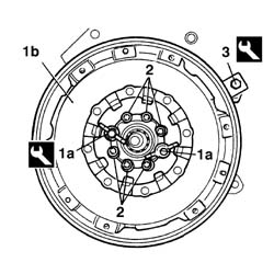
1. Fit the guide screws of tool (1a), locate engine flywheel (1b) on the screws, insert the guide cones and tighten the tool nuts (1a) until the flywheel-damper is centred.
Description
Code
Function
1a
Fitting tool
1.870.770.000
Fitting engine flywheel
2. Tighten the six bolts, remove the tool and tighten the remaining two bolts.3. Fit the flywheel locking tool.
Description
Code
Function
3
Counter-torque
1.860.846.000
Flywheel lock
Engines: 2.0 JTD 8V
- Tighten all the bolts to the recommended torque.
Value - daNm
Fastening
Component
Ø
.
4,8
Bolt
FLYWHEEL (MECH.)
-
- Remove the tool.
Description
Code
Function
.
Counter-torque
1.860.846.000
Flywheel lock
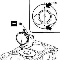
- Measure the piston projection (1a) at two points 180° apart on the piston pin centre line using tool (1b) and take the average of the two values measured for each piston.
Description
Code
Function
1b
Dial gauge support
1.870.404.000
Piston projection from cylinder head support plane check
Engines: 2.0 JTD 8V
1. Select the correct size cylinder head gasket depending on the maximum value between of the averages of the protrusion for each individual piston.
Subject
Value
1
CYLINDER HEAD GASKET
mm
-
Size
1,30
-
Average protrusion
0,470 - 0,605
Subject
Value
1
CYLINDER HEAD GASKET
mm
-
Size
1,35
-
Average protrusion
0,605 - 0,655
Subject
Value
1
CYLINDER HEAD GASKET
mm
-
Size
1,40
-
Average protrusion
0,655 - 0,705
Subject
Value
1
CYLINDER HEAD GASKET
mm
-
Size
1,45
-
Average protrusion
0,705 - 0,755
Subject
Value
1
CYLINDER HEAD GASKET
mm
-
Size
1,50
-
Average protrusion
0,755 - 0,830
Engines: 2.0 JTD 8V
1. Turn the camshaft until the 8 mm timing reference pinn fits into the seat on the cylinder head.2. Turn the crankshaft until the TDC reference tool fits into the seat on the flywheel.
Description
Code
Function
2
Pin
1.860.863.000
Crankshaft TDC reference
Engines: 2.0 JTD 8V
1. Position the cylinder head locating bushes on the engine block.2. Position the cylinder head gasket on the cylinder block/crankcase.- Position the cylinder head.
Engines: 2.0 JTD 8V
1. Check that retaining bolt length does not exceed the specified value: if so, replace it.
Subject
Value
1
CYLINDER HEAD RETAINING ELEMENTS
mm
-
Retaining bolt length
133,4
Engines: 2.0 JTD 8V
- Lubricate the bolt thread and mating surface.1. Tighten the cylinder head bolts to the specified torque in the order shown. Use an Usag tool or similar for angular tightening.
Value - daNm
Fastening
Component
Ø
1
2,0 + 6,0 + 220°
Bolt
CYLINDER HEAD
-
Engines: 2.0 JTD 8V
- Fit the engine timing sensor and tighten the retaining bolt.- Fit the gasket and cam cover and tighten the ten bolts to torque.
Value - daNm
Fastening
Component
Ø
.
1,0
Bolt
CAM COVER
-
- Apply sealant to the engine water pump contact surfaces.
Description
Qty.
Component
Type
Classification
.
Dow Corning 7091
-
COOLANT PUMP
Silicone sealant
-
- Fit the coolant pump and tighten the bolts to the recommended torque.
Value - daNm
Fastening
Component
Ø
.
1,5
Bolt
COOLANT PUMP
-
1. Fit the crankshaft drive gear by positioning both tabs (1b).2. Fit the timing belt mobile tensioner (2a) and tighten the fixed tensioner bolt (2b).3. Fit the timing belt idle gear (3a) and tighten bolt (3b) to the specified torque.
Value - daNm
Fastening
Component
Ø
3b
4.3
Bolt
FIXED TENSIONER
-
Engines: 2.0 JTD 8V
1. Remove the 8 mm diameter timing reference pin from its seat on the cylinder head.2. Remove the TDC reference tool from its seat on the flywheel.
Description
Code
Function
2
Pin
1.860.863.000
Crankshaft TDC reference
Engines: 2.0 JTD 8V
- Fit the camshaft pulley and screw in without tightening the bolts.1. Fit the high pressure pump mount (1a) and tighten bolts (1b) to the specified torque. Observed the position indicated.
Value - daNm
Fastening
Component
Ø
1b
2
Bolt
INJECTION PRESSURE PUMP MOUNT
-
Engines: 2.0 JTD 8V
- Fit the fuel manifold and tighten the bolts to the recommended torque.
Value - daNm
Fastening
Component
Ø
2,3
Bolt
INJECTOR FUEL MANIFOLD (DIESEL)
-
1. Fit the high pressure pipe.2. Use a wrench and counterwrench to tighten the manifold side high pressure pipe connector to the specified torque.
Value - daNm
Fastening
Component
Ø
2
2,0
Connector
PIPE FUEL MANIFOLD TO INJECTORS
-
3. Use a wrench and counterwrench to tighten the injector side pipe connector to the specified torque.
Value - daNm
Fastening
Component
Ø
3
2,0
Connector
PIPE FUEL MANIFOLD TO INJECTORS
-
Engines: 2.0 JTD 8V
- Repeat the operations for all injectors.- Fit the high pressure pump and tighten the nuts to the recommended torque.
Value - daNm
Fastening
Component
Ø
.
2,3
Bolt
PRESSURE PUMP
-
- Fit the rear bracket and tighten the bolts to the recommended torque.
Value - daNm
Fastening
Component
Ø
.
2,3
Bolt
PRESSURE PUMP
-
- Fit the high pressure pipe and use a wrench and counterwrench to tighten the pump side connector and manifold side connector to the specified torque.
Value - daNm
Fastening
Component
Ø
.
2
Connector
PRESSURE PUMP LINE TO FUEL MANIFOLD
-
1. Fit the pressure pump pulley.2. Use tool (2a) to tighten the retaining bolt (2b) to the specified torque.
Description
Code
Function
2a
Counter-torque
1.860.831.000
Timing pulley lock
Description
Code
Function
2a
Counter-torque
1.860.831.001
Timing pulley lock
Value - daNm
Fastening
Component
Ø
2b
2,0
Bolt
PRESSURE PUMP CONTROL PULLEY
-
Engines: 2.0 JTD 8V
1. Loosen bolts (1a) securing camshaft pulley (1b).2. Fit the timing belt over the pulleys in the following order.- Check that the engine is at TDC and the camshaft reference is aligned.3. Fit the tool C-TRONIC - 105.5 facing downward4. Unscrew bolt (4a) securing tensioner (4b) and use a ¼" box wrench to tension the belt to the specified value.
Subject
Value
.
Timing belt/s
unità seem
-
Timing belt tension
108
- Lock the tensioner bolt and pulley retaining bolts.- Turn the engine through 8 revolutions without going backwards.
Engines: 2.0 JTD 8V
- Turn the engine clockwise without going backward until the TDC reference tool enters its seat on the flywheel.
Description
Code
Function
.
Pin
1.860.863.000
Crankshaft TDC reference
1. Loosen screw (1a) securing pulley (1b), then turn the camshaft until the 8 mm timing reference pin (1c) enters its seat on the cylinder head through the pulley.2. Fit the tool C-TRONIC - 105.5 facing downward3. Unscrew bolt (3a) securing tensioner (3b) and use a ¼" box wrench to tension the belt to the specified value.
Subject
Value
.
Timing belt/s
unità seem
-
Timing belt tension
54
Engines: 2.0 JTD 8V
- Lock the tensioner bolt and pulley retaining bolts.- Remove the tool C-TRONIC - 105.5- Refit the tool C-TRONIC - 105.5 and check that belt tension is within specified limits.
Subject
Value
.
Timing belt/s
unità seem
-
Timing belt tension
51 - 57
- Remove the tool C-TRONIC - 105.5- Remove the TDC reference tool.
Description
Code
Function
.
Pin
1.860.863.000
Crankshaft TDC reference
- Remove the 8 mm diameter timing reference pin.- Turn the engine through two revolutions clockwise without going backward until the TDC reference tool enters its seat on the flywheel.
Description
Code
Function
.
Pin
1.860.863.000
Crankshaft TDC reference
- Check that the 8 mm timing reference pin enters its seat on the cylinder heat extension through the pulley.- If not, loosen the pulley retaining bolts and turn the camshaft anticlockwise until the 8 mm diameter timing reference pin enters its seat on the cylinder head extension through the pulley.- Lock the pulley retaining bolts.- Repeat the check.- Remove the TDC reference tool.
Description
Code
Function
.
Pin
1.860.863.000
Crankshaft TDC reference
- Remove the 8 mm diameter timing reference pin.- Tighten the pulley retaining bolts to the recommended torque.
Value - daNm
Fastening
Component
Ø
.
2,0
Bolt
TIMING DRIVEN PULLIES
-
- Tighten the tensioner bolt to the recommended torque.
Value - daNm
Fastening
Component
Ø
.
2,3
Bolt
MOBILE TIMING TENSIONER
-
1. Fit engine mount (1a) and tighten bolts (1b) and (1c) to the specified torque.
Value - daNm
Fastening
Component
Ø
1b
2,0
Bolt
RIGID ENGINE MOUNT, TIMING SIDE
-
Value - daNm
Fastening
Component
Ø
1c
4,5
Bolt
RIGID ENGINE MOUNT, TIMING SIDE
-
Engines: 2.0 JTD 8V
- Fit the timing belt lower cover, upper cover and front cover in order and tighten the retaining bolts.- Fit the flywheel locking tool.
Description
Code
Function
.
Counter-torque
1.860.846.000
Flywheel lock
- Fit the accessory drivebelt pulley.- Tighten the retaining bolt to the specified torque. Use USAG tool (1b) or similar for angular tightening.
Value - daNm
Fastening
Component
Ø
.
4,0 + 51°
Bolt
CRANKSHAFT PULLEY
-
- Fit the clutch assembly and tighten the bolts.- Remove the tool.
Description
Code
Function
.
Counter-torque
1.860.846.000
Flywheel lock
- Fit the oil vapour recirculation pipe from the engine block and cylinder head cover.- Fit the oil dipstick and tighten the bolt.- Fit the fuel temperature sensor and tighten the bolt.- Fit the compressor, position the profiled shims and nuts correctly and tighten the retaining bolts.- Fit the power steering pump mount complete with pump and pipes and tighten the retaining bolts.1. Fit thermostat (1a) with a new gasket complete with coolant pump connection pipe and tighten nuts (1b) and bolts (1c) to the specified torque.
Value - daNm
Fastening
Component
Ø
1b
2,0
Nut
THERMOSTAT
-
Value - daNm
Fastening
Component
Ø
1c
2,0
Bolt
THERMOSTAT
-
Engines: 2.0 JTD 8V
- Fit the oil-water exchanger with gasket and tighten the connector.- Connect the coolant inlet and outlet pipes to the exchanger.- Fit both wire and pipe brackets, tighten the retaining bolts and secure the pipes with the bands provided.- Fit the coolant manifold with a new gasket and tighten the bolts to the recommended torque.
Value - daNm
Fastening
Component
Ø
.
1,8
Bolt
ENGINE FLUID INTAKE FITTING
-
- Connect the pipes to the manifold using the bands provided.- Fit intake manifold (1a) complete with plastic sleeve with a set of new gaskets and tighten bolts (1b) and nuts (1c) to the specified torque in the order shown.
Value - daNm
Fastening
Component
Ø
1b
2,3
Bolt
INLET MANIFOLD
-
Value - daNm
Fastening
Component
Ø
1c
2,3
Nut
INLET MANIFOLD
-
Engines: 2.0 JTD 8V
1. Fit exhaust manifold (1a) complete with EGR valve and pipe, spacers and a set of new gaskets and tighten nuts (1b) to the specified torque in the order shown.
Value - daNm
Fastening
Component
Ø
1b
2,0
Nut
EXHAUST MANIFOLD/S
-
2. Tighten the bolts securing the EGR pipe.
Engines: 2.0 JTD 8V
- Position the turbocharger assembly, tighten the oil delivery fitting and place the turbocharger on its flange.- Tighten the lower mounting nut.- Tighten the four flange nuts.- Fit the oil return pipe.- Fit the intake sleeve and tighten the sleeve retaining bolt.- Fit the oil vapour intake manifold and connect the hose to the turbocharger using the bands provided.- Fit the pneumatic connection pipes to the EGR valve and wastegate.- Fit the duct with wiring and tighten the bolts.- Connect the electrical connections.
Description
Connector
.
Injector
N070A
Description
Connector
.
Injector
N070B
Description
Connector
.
Injector
N070C
Description
Connector
.
Injector
N070D
Description
Connector
.
Heater plugs
A040A
Description
Connector
.
Air conditioning compressor engagement electro-magnet
L020
Description
Connector
.
Timing sensor
K047
Description
Connector
.
Injection pump third piston deactivation solenoid valve
L005
Description
Connector
.
Fuel pressure regulator
N077
Description
Connector
.
Engine coolant temperature sensor/sender unit
K036
Description
Connector
.
Heater plugs
A040B
Description
Connector
.
Heater plugs
A040C
Description
Connector
.
Heater plugs
A040D
Description
Connector
.
Fuel pressure sensor
K083
Description
Connector
.
Engine oil pressure sensor
K028
- Do up all the wire retaining bands. See in Op. 1004D40