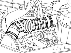
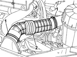
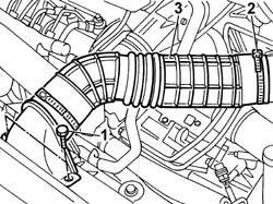
- Position the vehicle on a lift.1. Disconnect the intake hose from the air filter casing and from the cold intake on the crossmember.2. Remove the cold intake and intake hose assembly from the engine compartment.
Engines: 2.0 JTD 8V
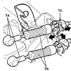
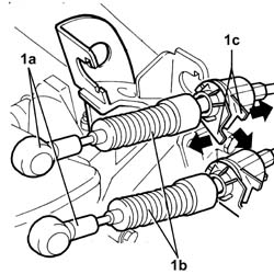
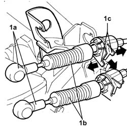
See in Op. 1048A101. Release the two ends (1a), move the two gear selector and engagement flexible cables (1b) out of the slot in the bracket (1c) and place them outside of the work area.
Engines: 2.0 JTD 8V
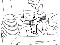
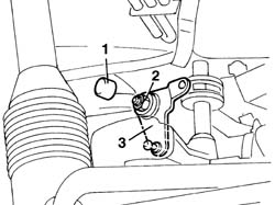
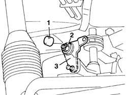
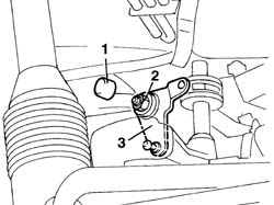
- Raise the vehicle. Op. 7055B54 UNDER-ENGINE GUARD - R R1. Remove the cover (1a), undo the nut (1b) and remove the selector unit idler connecting rod (1c).
Engines: 2.0 JTD 8V
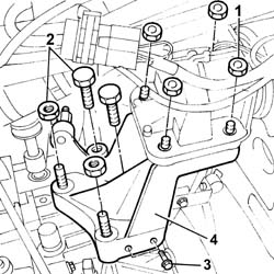
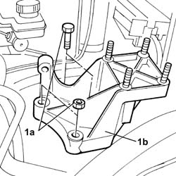
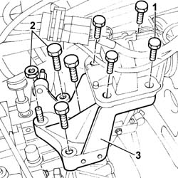
1. Undo the nuts fixing the gearbox side flexible mounting to the rigid support.2. Undo the bolts and the nut fixing the rigid support to the gearbox.- Gently lower the engine until the studs on the rigid support comes out of the housing in the flexible mounting.3. Undo the bolts fixing the rigid engine coolant pipe between the radiator and thermostat flexible hoses.4. Remove the gearbox side rigid power unit support.
- Fit the gearbox side rigid engine support.- Tighten the nuts fixing the gearbox side flexible mounting to the rigid support.
Value - daNm
Fastening
Component
Ø
.
(Rigid mount) 5
Bolt
GEARBOX SIDE RUBBER MOUNT
M10
- Tighten the bolts and the nuts fixing the rigid support to the gearbox to torque.
Value - daNm
Fastening
Component
Ø
.
(Gearbox) 9
Nut
GEARBOX SIDE RUBBER MOUNT
M14
Value - daNm
Fastening
Component
Ø
.
(Gearbox) 9
Bolt
GEARBOX SIDE RUBBER MOUNT
M14
- Tighten the bolts fixing the rigid engine coolant pipe between the radiator and thermostat flexible hoses.- Remove the hydraulic arm positioned previously to support the gearbox.- Fit the idler connecting rod on the gear selector and enagement assembly, tighten the nut and fit the plug. Op. 7055B54 UNDER-ENGINE GUARD - R R- Lock the ends of the gear selector and engagement flexible cables.- Secure the cables to the mounting bracket.- Fit the air supply hose to the turbocharger and secure it to the air filter casing. See in Op. 1048A10- Fit the cold intake and intake hose assembly in the engine compartment.- Connect the intake hose to the air filter casing and to the cold intake on the crossmember.- Remove the vehicle from the lift.
- Place the rigid support in position.- Tighten the fixing nuts and bolts and check the torque.- Fit the idler connecting rod on the gear selector and enagement assembly, tighten the nut and fit the plug.- Lock the ends of the gear selector and engagement flexible cables.- Secure the cables to the mounting bracket. See in Op. 1008B30 Op. 7055B54 UNDER-ENGINE GUARD - R R Op. 1048A12 AIR CLEANER SUPPORT - R R WITH AIR CLEANER ASSEMBLY REMOVED See in Op. 1048A10
1. Disconnect the intake hose from the air filter casing and from the cold intake on the crossmember.2. Remove the intake hose from the engine compartment.
Engines: 2.0 16V
See in Op. 1048A101. Release the two ends (1a), move the two gear selector and engagement flexible cables (1b) out of the slot in the bracket (1c) and place them outside of the work area.
Engines: 2.0 16V
Op. 7055B54 UNDER-ENGINE GUARD - R R- Lower the vehicle and position a hydraulic arm support beneath the gearbox to support the engine.1. Remove the cover.2. Undo the nut3. Remove the idler connecting rod for the selector unit.
Engines: 2.0 16V
1. Undo the nuts fixing the gearbox side flexible mounting to the rigid support.2. Undo the bolts and the nut fixing the rigid support to the gearbox.- Gently lower the engine until the studs on the rigid support comes out of the housing in the flexible mounting.3. Remove the gearbox side rigid power unit support.
- Fit the gearbox side rigid engine support.- Tighten the nuts fixing the gearbox side flexible mounting to the rigid support.
Value - daNm
Fastening
Component
Ø
.
(Rigid mount) 5
Nuts
GEARBOX SIDE RUBBER MOUNT
M10
- Tighten the bolts and the nuts fixing the rigid support to the gearbox to torque.
Value - daNm
Fastening
Component
Ø
.
(Gearbox) 9
Nut
GEARBOX SIDE RUBBER MOUNT
M14
Value - daNm
Fastening
Component
Ø
.
(Gearbox) 9
Bolt
GEARBOX SIDE RUBBER MOUNT
M14
- Remove the hydraulic arm positioned previously to support the gearbox.- Fit the idler connecting rod on the gear selector and enagement assembly, tighten the nut and fit the plug. Op. 7055B54 UNDER-ENGINE GUARD - R R- Lock the ends of the gear selector and engagement flexible cables.- Secure the cables to the mounting bracket.- Fit the air supply hose to the turbocharger and secure it to the air filter casing. See in Op. 1048A10- Fit the intake hose.- Connect the intake hose to the air filter casing and to the cold intake on the crossmember.- Remove the vehicle from the lift.
- Position the vehicle on a lift.1. Unscrew the bolts securing the cold air intake to the upper crossmember.2. Disconnect the intake sleeve from the air cleaner case.3. Remove the intake and cold air input sleeve assembly from the engine bay.
Engines: 2.3 JTD 16V
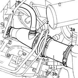
1. Disconnect the collar securing the air delivery sleeve to the turbocharger.2. Disconnect the vapour recovery pipe from the air delivery sleeve to the turbocharger.3. Disconnect the collar from air cleaner case (3a) and remove the air delivery sleeve to turbocharger (3b).
Engines: 2.3 JTD 16V
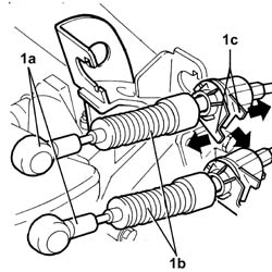
1. Prise up both heads (1a), move both gear selection and engagement cables (1b) out of the slot on bracket (1c) and place outside the working area.
Engines: 2.3 JTD 16V
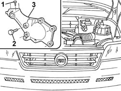
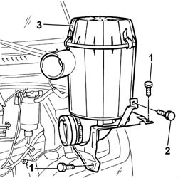
1. Unscrew the air cleaner case bracket bolts.2. Undo the bolts securing the air cleaner case to the bracket joining it to the screen washer reservoir.3. Remove the air cleaner case from the engine bay.
1. Undo the bolts securing the flexible gearbox side block to its rigid support.2. Undo the bolts and nut securing the rigid support to the gearbox.- Slightly lower the engine until the stud on the rigid mount emerges from its seat on the flexible block.3. Remove the gearbox side rigid engine mount.
- Fit the gearbox side rigid engine mount.- Tighten the bolts securing the flexible gearbox side block to its rigid support to torque.
Value - daNm
Fastening
Component
Ø
.
(Rigid mount) 5
Bolt
GEARBOX SIDE RUBBER MOUNT
M10
- Tighten the bolts and nut securing the rigid support to the gearbox to torque.
Value - daNm
Fastening
Component
Ø
.
(Gearbox) 9
Nut
GEARBOX SIDE RUBBER MOUNT
M14
- Remove the hdyraulic arm positioned previously to support the gearbox.- Fit the idler rod to the gear selection and engagement unit, tighten the nut and apply the relevant plug. Op. 7055B54 UNDER-ENGINE GUARD - R R- Fit the air cleaner case.- Screw in the bolt securing the air cleaner case to the bracket joining it to the screen washer reservoir.- Screw in the air cleaner case bracket bolts.- Press home the gear selection and engagement cable heads.- Secure the cables to the bracket.- Fit the air delivery sleeve to the turbocharger and secure to the air cleaner case.- Connect the vapour recovery pipe to the air delivery sleeve.- Fit the intake and cold air input sleeve assembly in the engine bay.- Connect the intake sleeve to the air cleaner case.- Screw in the bolts securing the cold air intake to the upper crossmember.- Remove the vehicle from the lift.