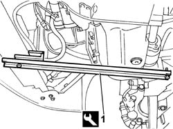
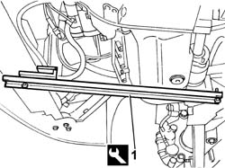
- Position the vehicle on the lift. Op. 7055B54 UNDER-ENGINE GUARD - R R1. Position the tool for supporting the power unit fastened to the crossmember for the suspension and to the lower crossmember under the engine oil sump.
Description
Code
Function
.
Engine mounting beam
1.870.735.000
Support power unit
Engines: 2.0 JTD 8V
- Lower the lift.1. Undo the bolts securing the power steering fluid reservoir bracket.2. Remove the power assisted steering fluid reservoir complete with bracket.
Engines: 2.0 JTD 8V
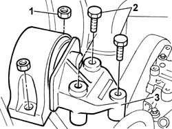
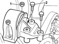
1. Undo the bolts and the nut fixinf the flexible mounting to the rigid power unit support on the engine.2. Undo the nuts fixing the flexible mounting to the bodyshell.3. Remove the flexible mounting from the engine compartment.
- Fit the flexible mounting in the housing in the engine compartment.- Tighten the nuts fixing the flexible mounting to the bodyshell.
Value - daNm
Fastening
Component
Ø
.
(body block) 5
Nuts
FRONT FLEXIBLE MOUNTING BLOCKS, POWER UNIT
M10
- Tighten the nut and the two bolts fixing the flexible mounting to the timing side rigid power unit support to torque.
Value - daNm
Fastening
Component
Ø
.
(Rigid mount on engine) 5
Bolt
FRONT FLEXIBLE MOUNTING BLOCKS, POWER UNIT
M10
Value - daNm
Fastening
Component
Ø
.
(Rigid mount on engine) 8
Nut
FRONT FLEXIBLE MOUNTING BLOCKS, POWER UNIT
M12
- Fit the engine coolant reservoir and tighten the nuts fixing it to the bodyshell.- Connect the coolant delivery pipe to the pump.- Fasten the electrical connection in the housing on the tank.- Connect the band retaining the coolant pipe to the cylinder head.- Fit the power steering fluid reservoir complete with bracket.- Remove the tool used to support the power unit previously secured to the suspension beam and lower crossmember from beneath the engine sump.
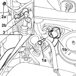
1. Undo the bolt (1a) fixing the air conditioning pipe (1b).2. Undo the nut (2a) fixing the air conditioning pipes mounting bracket (2b).3. Move the pipe outside of the work area.
Engines: 2.8 JTD 8V
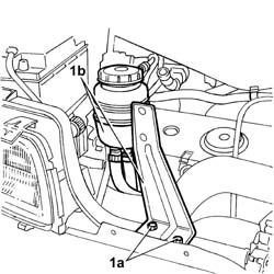
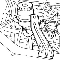
1. Undo the fixing bolts (1a) and move the power assisted steering fluid reservoir, complete with mounting bracket (1b), away from the work area.
Engines: 2.8 JTD 8V
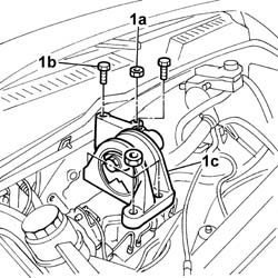
1. Undo the nuts (1a) and the bolts (1b) fixing the timing side flexible mounting (1c) and remove it.
- Place the flexible mounting in position.- Tighten the nuts and the bolts to torque.- Remove the tool used to support the power unit previously secured to the suspension beam and lower crossmember from beneath the engine sump.
Op. 7055B54 UNDER-ENGINE GUARD - R R- Lower the vehicle and position a hydraulic arm support underneath the engine oil sump to support the engine.- Lower the lift.1. Undo the bolts securing the power steering fluid reservoir bracket.2. Move the power assisted steering fluid reservoir complete with bracket aside.
Engines: 2.0 16V
1. Undo the bolts fixing the flexible mounting to the rigid power unit support on the engine.2. Undo the nuts fixing the flexible mounting to the bodyshell.3. Remove the flexible mounting from the engine compartment.
- Fit the flexible mounting in the housing in the engine compartment.- Tighten the nuts fixing the flexible mounting to the bodyshell.
Value - daNm
Fastening
Component
Ø
.
(body block) 5
Nuts
FRONT FLEXIBLE MOUNTING BLOCKS, POWER UNIT
M10
- Tighten the nut and the two bolts fixing the flexible mounting to the timing side rigid power unit support to torque.
Value - daNm
Fastening
Component
Ø
.
(Rigid mount on engine) 5
Bolt
FRONT FLEXIBLE MOUNTING BLOCKS, POWER UNIT
M10
Value - daNm
Fastening
Component
Ø
.
(Rigid mount on engine) 8
Bolt
FRONT FLEXIBLE MOUNTING BLOCKS, POWER UNIT
M12
- Fit the power steering fluid reservoir complete with bracket.- Remove the hydraulic arm from underneath the engine oil sump to support the power unit. Op. 7055B54 UNDER-ENGINE GUARD - R R
- Position the vehicle on the lift. Op. 7055B54 UNDER-ENGINE GUARD - R R1. Position a tool to support the power unit beneath the engine oil sump and secure it to the suspension beam and lower crossmember.
Description
Code
Function
1
Crossmember
1.870.735.000
Lower engine mounting beam
Engines: 2.3 JTD 16V
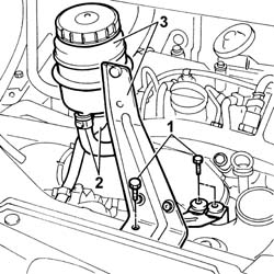
- Lower the lift.1. Undo the bolts securing the power steering fluid reservoir mounting bracket.2. Disconnect the oil pipes from the reservoir.3. Remove the power steering reservoir with bracket.
Engines: 2.3 JTD 16V
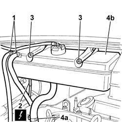
1. Disconnect the band retaining the coolant pipe to the reservoir.2. Release the electrical connection shown from the connection on the reservoir.3. Undo the nuts securing the expansion tank.4. Disconnect pipe (4a) carrying coolant to the coolant pump and remove expansion tank (4b).
Engines: 2.3 JTD 16V
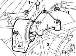
1. Undo the bolts and nut securing the flexible block to the rigid power unit mount on the engine.2. Undo the nuts securing the engine block to the body.3. Remove the flexible mount from the engine compartment.
- Fit the flexible block into its seat in the engine bay.- Tighten the nuts securing the engine block to the body to torque.
Value - daNm
Fastening
Component
Ø
.
(body block) 5
Nuts
FRONT FLEXIBLE MOUNTING BLOCKS, POWER UNIT
M10
- Tighten the nut and both bolts securing the flexible block to the rigid power unit mount, timing side.
Value - daNm
Fastening
Component
Ø
.
(Rigid mount on engine) 5
Bolt
FRONT FLEXIBLE MOUNTING BLOCKS, POWER UNIT
M10
Value - daNm
Fastening
Component
Ø
.
(Rigid mount on engine) 8
Nut
FRONT FLEXIBLE MOUNTING BLOCKS, POWER UNIT
M12
- Fit the engine coolant reservoir and tighten the nuts securing it to the body.- Connect the coolant delivery pipe to the pump.- Secure the electrical connection in its seat on the reservoir.- Connect the band retaining the coolant pipe to the cylinder head.- Fit the power steering reservoir with bracket.- Connect the oil pipes to the reservoir and tighten the bolts securing the power steering fluid reservoir bracket to the crossmember.- Remove the tool used to support the power unit previously secured to the suspension beam and lower crossmember from beneath the engine sump.