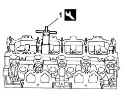
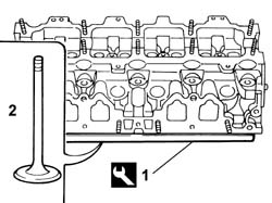
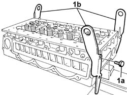
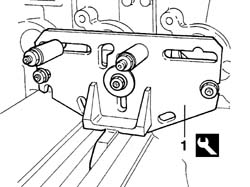
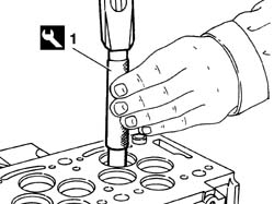
- Fit the tool to the cylinder head and secure in the vice.
Description
Code
Function
.
Support
1.860.470.000
Cylinder head in vice
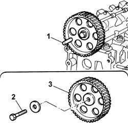
1. Check that the 10 mm diameter reference pin is correctly inserted.2. Undo the gear retaining bolt.3. Remove the gear.- Remove the 10 mm diameter reference pin.
Engines: 2.0 16V
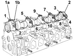
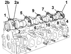
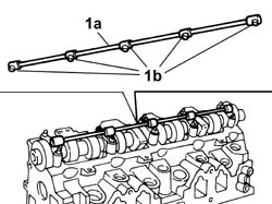
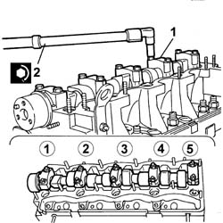
- Remove the spark plugs.- Remove the press-fitted lubrication pipe and the sealing rings.1. Unscrew nuts (1a) securing the camshaft caps in the order shown and remove caps (1b).2. Remove the camshaft.
Engines: 2.0 16V
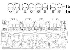
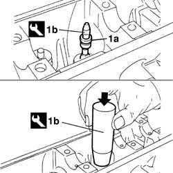
1. Remove tappets (1a) and calibrated valve clearance pads (1b).
Engines: 2.0 16V
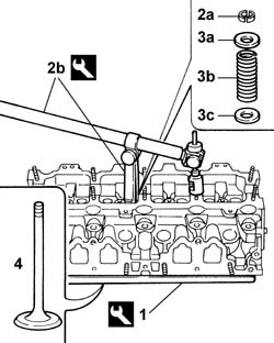
1. Fit the tool beneath the cylinder head.
Description
Code
Function
1
Valve retaining base
1.860.804.000
Valve retention
2. Remove semicones (2a) from the valve using tools (2b).
Description
Code
Function
2b
Tool
1.860.644.000
Removing/refitting valves
Description
Code
Function
2b
Tool
1.860.644.030
Removing/refitting valves
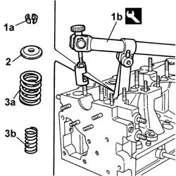
3. Remove upper plate (3a), spring (3b) and lower plate (3c) in order.- Repeat the operation for all valves.- Remove the tool.
Description
Code
Function
.
Valve retaining base
1.860.804.000
Valve retention
4. Remove all valves.
Engines: 2.0 16V
1. Remove the valve stem sealing ring using the tool.
Description
Code
Function
1
Extractor
1.860.792.000
Valve guide oil seals
- Repeat the operation for all valve stem sealing rings.
Engines: 2.0 16V
1. Remove the filter from the lubricant delivery channel to the cylinder head.
Engines: 2.0 16V
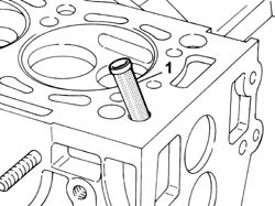
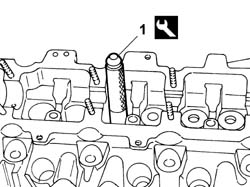
1. Remove the valve guide from its seat using the tool.
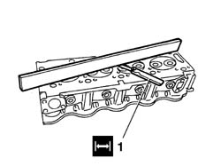
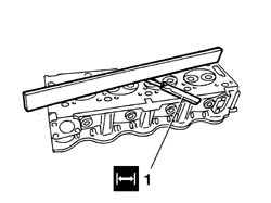
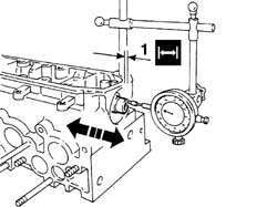
- Clean all ducts thoroughly.1. Check the lower surface and ensure that flatness is within specified limits.
Subject
Value
1
CYLINDER HEAD
mm
-
Flatness
0,05
Engines: 2.0 16V
- Fit the camshaft and caps provisionally.- Tighten the nuts to the recommended torque.
Value - daNm
Fastening
Component
Ø
.
1,6
Nut
CAMSHAFT CAPS
-
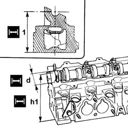
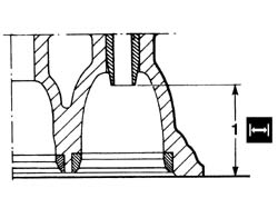
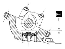
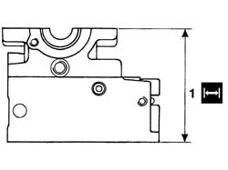
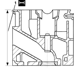
1. Check that cylinder head height is within recommended limits.
Subject
Value
1
CYLINDER HEAD
mm
-
Height
140,95 - 141,05
- Remove the caps and camshaft.- If cylinder head flatness and/or height are not within specified limits, grind the lower surface to reduce the height to the specified value.
Subject
Value
.
CYLINDER HEAD
mm
-
Cylinder head height reduction
0,20
Engines: 2.0 16V
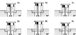
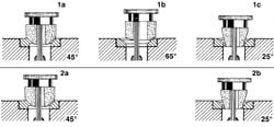
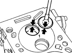
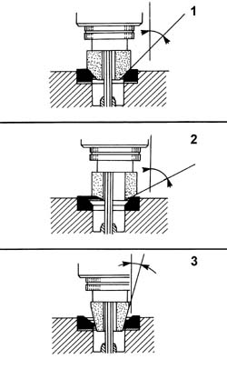
1. Grind the intake valve seats using a suitable tool.
Subject
Value
1a
VALVE SEATS
-
Contact band angle with intake valve
45°
Subject
Value
1b
VALVE SEATS
-
Intake port outlet angle
65°
Subject
Value
1c
VALVE SEATS
-
Intake port intake angle
25°
2. Grind the exhaust valve seats using a suitable tool.
Subject
Value
2a
VALVE SEATS
-
Contact band angle with intake valve
45°
Subject
Value
2b
VALVE SEATS
-
Exhaust port outlet angle
65°
Subject
Value
2c
VALVE SEATS
-
Exhaust port intake angle
20°
Subject
Value
.
VALVE SEATS
mm
-
Intake valve contact band width
1,70
-
Exhaust valve contact band width
2,20
Engines: 2.0 16V
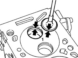
1. Check contact between valve and seat is correct after grinding.
Engines: 2.0 16V
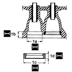
- If it is not possible to obtain centred, even contactg between valve and seat, replace the valve seat.1. Whenever necessary, replace the valve seats using new oversize valve seats to restore the initial conditions.
Subject
Value
1a
VALVE SEATS
mm
-
Intake valve seat housing diameter, 1st oversize
42,3
-
Intake valve seat housing diameter, 2nd oversize
42,5
Subject
Value
1a
VALVE SEATS
mm
-
Exhaust valve seat housing diameter, 1st oversize
36,3
-
Exhaust valve seat housing diameter, 2nd oversize
36,5
Subject
Value
1b
VALVE SEATS
mm
-
Intake valve seat housing height
15,98
-
Exhaust valve seat housing height
15,25
Subject
Value
1c
VALVE SEATS
mm
-
Intake valve seat diameter, 1st oversize
42,4
-
Intake valve seat diameter, 2nd oversize
42,6
Subject
Value
1c
VALVE SEATS
mm
-
Exhaust valve seat diameter, 1st oversize
36,4
-
Exhaust valve seat diameter, 2nd oversize
36,6
Subject
Value
1d
VALVE SEATS
mm
-
Oversize intake valve seat height
8,40
-
Oversize exhaust valve seat height
7,35
Engines: 2.0 16V
- Ream the valve guide seats using a suitable tool.
Subject
Value
.
VALVE GUIDES
mm
-
Valve guide seat diameter, 1st oversize
13,195 - 13,227
-
Valve guide seat diameter, 2nd oversize
13,495 - 13,527
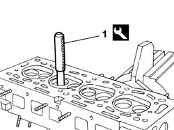
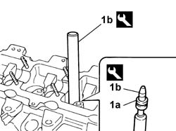
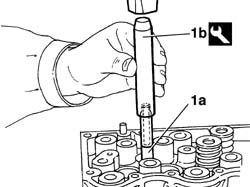
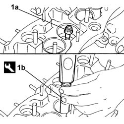
1. Press-fit new valve guides (1a) from the top of the cylinder head using tool (1b).
Description
Code
Function
1b
Fitting tool
1.870.751.000
Valve guide fitting
Engines: 2.0 16V
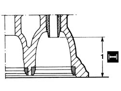
1. Check that valve guide position is within specified limits.
Subject
Value
1
VALVE GUIDES
mm
-
Gap between intake valve guide - lower cylinder head surface
43,65 - 44,35
-
Gap between exhaust valve guide - lower cylinder head surface
38,05 - 38,75
Engines: 2.0 16V
- Ream the valve guides using an appropriate tool
Subject
Value
.
VALVE GUIDES
mm
-
Valve guide bore
8,000 - 8,022
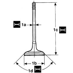
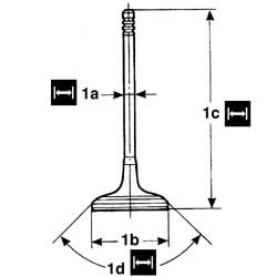
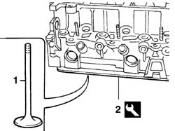
1. Check that the valve specifications are within specified limits; if not, replace the valves.
Subject
Value
1a
INLET VALVES
mm
-
Stem diameter
7.965 - 7,980
Subject
Value
1b
INLET VALVES
mm
-
Head diameter
41,4 - 41,8
Subject
Value
1c
INLET VALVES
mm
-
Height
108,8, mm
Subject
Value
1d
INLET VALVES
-
Contact angle
45°
Subject
Value
1a
EXHAUST VALVES
mm
-
Stem diameter
7.955 - 7,970
Subject
Value
1b
EXHAUST VALVES
mm
-
Head diameter
34,3 - 34,7
Subject
Value
1c
EXHAUST VALVES
mm
-
Height
108,4
Subject
Value
1d
EXHAUST VALVES
-
Contact angle
45°30'
Engines: 2.0 16V
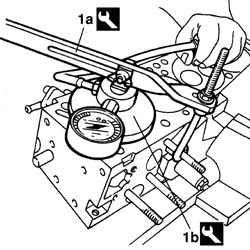
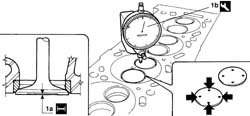
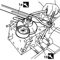
- Fit the valves and spark plugs provisionally as described later.1. Carry out a valve leak test using tools (1a) and (1b).
Description
Code
Function
1a
Lever
1.860.490.000
Valve leakage test
Description
Code
Function
1b
Sealing pad with pressure gauge
1.895.868.000
Valve leakage test
Engines: 2.0 16V
- Using a torque wrench, check that the valve spring specifications meet specified limits; if not, replace the springs.
Subject
Value
.
EXTERNAL VALVE SPRING
-
Length
54,5 mm
-
Under a load of
0 daN
Subject
Value
.
EXTERNAL VALVE SPRING
-
Length
42,5 mm
-
Under a load of
39 daN
Subject
Value
.
EXTERNAL VALVE SPRING
-
Length
31,0 mm
-
Under a load of
85 daN
- Fit the tool to the cylinder head and secure in the vice.
Description
Code
Function
.
Support
1.860.470.000
Cylinder head in vice
- Fit a new filter in the lubricant delivery channel to the cylinder head.1. Fit all the valve in their valve guides.2. Fit the tool beneath the cylinder head.
Description
Code
Function
2
Valve retaining base
1.860.804.000
Valve retention
Engines: 2.0 16V
1. Fit the sealing ring (1a) into its seat using tool (1b).
Description
Code
Function
1b
Fitting tool
1.860.313.000
Valve guide oil seal fitting.
Engines: 2.0 16V
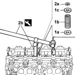
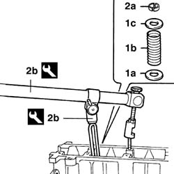
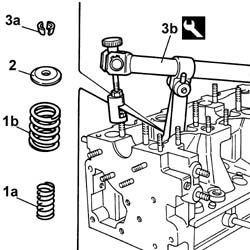
- Repeat the operation for all rings.1. Fit the lower plate (1a), spring (1b) and upper plate (1c) in order, respecting the marks made upon disassembly.2. Fit semicones (2a) and settle in their seats using tools (2b).
Description
Code
Function
2b
Tool
1.860.644.030
Removing/refitting valves
Description
Code
Function
2b
Tool
1.860.644.000
Removing/refitting valves
Engines: 2.0 16V
- Repeat the operation for all valves.1. Fit the calibrated pads to adjust the clearance. Ensure they are fitted in the correct direction.2. Fit the tappets in their housing.
Engines: 2.0 16V
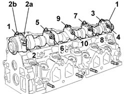
1. Fit the camshaft.2. Fit the camshaft caps (2a) and tighten retaining nuts (2b) to the specified torque in the order shown.
Value - daNm
Fastening
Component
Ø
2b
1,6
Nut
CAMSHAFT CAPS
-
Engines: 2.0 16V
- Fit the timing gear provisionally.1. 1. Position each cam upright and check the clearance is within specified limits.
Subject
Value
.
VALVE TAPPETS
mm
-
Inlet valve clearance check
0,15 - 0,25
-
Exhaust valve clearance check
0,35 - 0,45
Engines: 2.0 16V
- if not as specified, remove the camshaft caps, camshaft and tappets.- Remove a calibrated pad and measure its thickness.- Calculate the difference between the measured clearance and the specified clearance for each pad.- Calculate the thickness of the pad to be fitted by adding the thickness of the current pad to the calculated difference (including the + or - sign).- Repeat the procedure for all calibrated pads.- Fit the tappets.1. Fit the camshaft.2. Fit the camshaft caps (2a) and tighten retaining nuts (2b) to the specified torque in the order shown.
Value - daNm
Fastening
Component
Ø
2b
1,6
Nut
CAMSHAFT CAPS
-
Engines: 2.0 16V
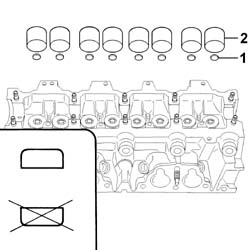
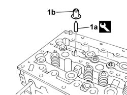
1. Press-fit the lubrication pipe (1a) and the sealing rings (1b).
1. Position the cylinder head in the vice supporting it using a suitable tool.
Description
Code
Function
1
Support
1.860.470.000
Cylinder head in vice
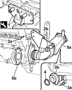
2. Undo the bolts (2a) and the nuts (2b).3. Undo the bolts (3a) and remove the connector (3b) from the cylinder head.4. Remove the seal.5. Remove the heat exchanger for the EGR (5a) and the gaskets (5b).
Engines: 2.3 JTD 16V
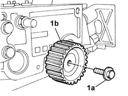
1. Undo the bolt (1a) and remove the fixed timing belt tensioner (1b).
Engines: 2.3 JTD 16V
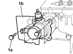
1. Undo the bolts (1a) and remove the thermostat (1b).
Engines: 2.3 JTD 16V
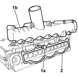
1. Undo the bolts (1a) and remove the intake manifold (1b).2. Remove the seal.
Engines: 2.3 JTD 16V
1. Undo the bolts (1a) and remove the brackets (1b).
Engines: 2.3 JTD 16V
- Position the tool for supporting the valves in the lower part of the cylinder head.
Description
Code
Function
1
Valve retaining base
1.860.804.000
Valve retention
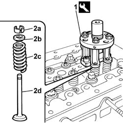
1. Compress the valve springs using the special tool.
Description
Code
Function
1
Tool
99360260
Valve spring compression
2. Release the cotters (2a), caps (2b) and springs (2c), then, removing the tools, release the valves (2d) from the cylinder head.
Engines: 2.3 JTD 16V
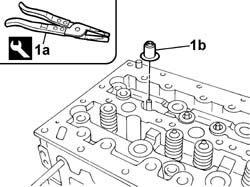
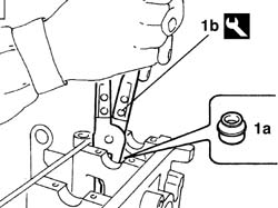
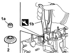
1. Remove the oil seals (1b) from the valve guides using pliers (1a).
- De-carbonize and clean the valve seats and ducts.- Clean any residues of the old gasket from the lower cylinder head plane.- Check that the planarity of the lower cylinder head plane corresponds to the recommended values.
Subject
Value
.
Cylinder head
mm
-
Lower plane planarity
0.1
- If the planarity of the lower cylinder head plane does not correspond to the recommended figures, regrind it without exceeding the minimum permitted height.- Check that the valves do not show signs of grooves or seizing.- Check that the diameter of the valve stems corresponds to the recommended figures; if not, replace the worn valves.
Subject
Value
.
INLET VALVES
mm
-
Stem diameter
5.985 - 6,000
Subject
Value
.
EXHAUST VALVES
mm
-
Stem diameter
5.975 - 5.990
See in Op. 1016E14- Using a torque wrench, check that the spring specifications correspond to the recommended figures; if not, replace the worn components.
Subject
Value
.
VALVE SPRINGS
mm
-
Length
45
-
Under a load of
23.1 - 25.5
Subject
Value
.
VALVE SPRINGS
mm
-
Length
35
-
Under a load of
50.9 - 55.7
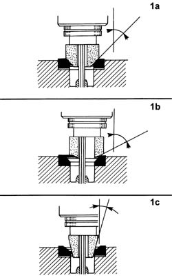
1. Grind the valve seats at (1a), (1b) and (1c) using a suitable tool.
Subject
Value
1a
VALVE SEATS
-
Contact band angle with inlet/exhaust valve
44° 25' - 44° 35'
Engines: 2.3 JTD 16V
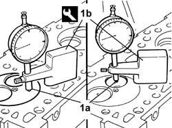
- Check that the valve recess in relation to the cylinder head plane corresponds to the recommended figures using the tool fitted with a magnetic base.
Description
Code
Function
.
Dial gauge support
1.870.404.000
Valve recess in cylinder head plane measurement
- If the valve recess in relation to the cylinder head plane does not correspond to the recommended figures, regrind the valve seats once again.- Fit all the valves in the correct positions.- Position the tool for supporting the valves in the lower part of the cylinder head.
Description
Code
Function
.
Valve retaining base
1.860.804.000
Valve retention
- Fit the oil seals (1b) on the valve stems using the tool (1a).
Description
Code
Function
.
Fitting tool
1.860.993.000
Fitting oil seals on valve stems
Engines: 2.3 JTD 16V
- Fit the valve springs and shims.- Compress the valve springs and fit the cotters using the special tool.
Description
Code
Function
.
Tool
99360260
Valve spring compression
- Remove the tools used for fitting the valves.
Description
Code
Function
.
Valve retaining base
1.860.804.000
Valve retention
Description
Code
Function
.
Tool
99360260
Valve spring compression
- Position the brackets and tighten the fixing bolts to the recommended torque.
Value - daNm
Fastening
Component
Ø
.
2.5
Bolt
HOISTS
M8 X 1.25
- Fit a new gasket, position the intake manifold and tighten the fixing bolts to the recommended torque.
Value - daNm
Fastening
Component
Ø
.
2.5
Bolt
INLET MANIFOLD
M8 X 1.25
- Position the thermostat and tighten the fixing bolts.- Fit the fixed timing belt tensioner and tighten the retaining bolt to the recommended torque.
Value - daNm
Fastening
Component
Ø
.
2.5
Bolt
FIXED TENSIONER
M8 X 1.25
- Fit the new gaskets, position the EGR heat exchanger and tighten the fixing bolts and nuts.- Connect the EGR heat exchanger connector to the cylinder head and tighten the fixing bolt.- Remove the cylinder head from the vice.- Remove the support tool.
1. Fit the tool on the cylinder head and secure the tool on a vice.
Description
Code
Function
1
Support
1.860.470.000
Cylinder head in vice
Engines: 2.0 JTD 8V
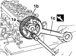
1. Undo bolts (1a) and remove pulley (1b) using tool (1c).
Description
Code
Function
1c
Counter-torque
1.860.776.000
Timing pulley lock
Engines: 2.0 JTD 8V
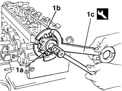
1. Undo central nut (1a) and remove flange (1b) using tool (1c).
Description
Code
Function
1c
Counter-torque
1.860.776.000
Timing pulley lock
Engines: 2.0 JTD 8V
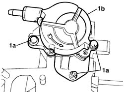
1. Undo the bolts and nut (1a) and remove the vacuum pump (1b).
Engines: 2.0 JTD 8V
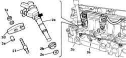
- Remove the fuel return pipe from the injector.1. Undo nut (1a) securing the injector bracket.2. Remove injector (2a), sealing ring (2b), washer (2c), bracket (2d) and support dowel (2e).- Repeat the operation for all the injectors.3. Remove spark plug supply lead (3a) and spark plugs (3b).
Engines: 2.0 JTD 8V
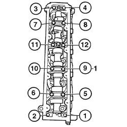
1. Undo the twelve bolts in the order indicated.
Engines: 2.0 JTD 8V
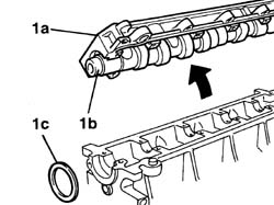
1. Remove the cylinder head extension (1a), camshaft (1b) and oil sealing ring (1c).
Engines: 2.0 JTD 8V
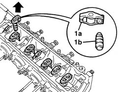
1. Remove rocker (1a) and tappet (1b).- Repeat the operation for all rocker-tappet assemblies.
Engines: 2.0 JTD 8V
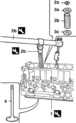
1. Fit the tool beneath the cylinder head.
Description
Code
Function
1
Valve retaining base
1.860.804.000
Valve retention
2. Remove half-cones (2a) from the valve using tools (2b).
Description
Code
Function
2b
Tool
1.860.644.000
Removing/refitting valves
Description
Code
Function
2b
Tool
1.860.877.000
Removing/refitting valves
3. Remove upper plate (3a), spring (3b) and lower plate (3c) in order.- Repeat the operation for all the valves.- Remove the tool.
Description
Code
Function
.
Valve retaining base
1.860.804.000
Valve retention
4. Remove all the valves.
Engines: 2.0 JTD 8V
1. Remove valve stem sealing ring (1a) using tool (1b).
Description
Code
Function
1b
Extractor
1.860.989.000
Valve guide oil seal extraction
- Repeat the operation for all the valve stem sealing rings.
Engines: 2.0 JTD 8V
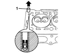
1. Remove the lubrication circuit check valve.
Engines: 2.0 JTD 8V
1. Remove the valve guides from their seats using the tool.
- Clean all the ports thoroughly.1. Check the lower surface and check that flatness is within specified limits.
Subject
Value
1
CYLINDER HEAD
mm
-
Flatness
0,05
Engines: 2.0 JTD 8V
1. Check that the cylinder head height is within the recommended limits.
Subject
Value
1
CYLINDER HEAD
mm
-
Height
132,95 - 133,05
- if cylinder head flatness and/or height are not within the specified limits, grind the lower surface without exceeding the minimum pemitted height.
Subject
Value
.
CYLINDER HEAD
mm
-
Minimum permitted height
132,55 - 132,65
Engines: 2.0 JTD 8V
1. Grind the intake valve seats using a suitable tool.
Subject
Value
1a
VALVE SEATS
-
Contact band angle with intake valve
45°
Subject
Value
1b
VALVE SEATS
-
Intake port outlet angle
65°
Subject
Value
1c
VALVE SEATS
-
Intake port intake angle
25°
2. Grind the exhaust valve seats using a suitable tool.
Subject
Value
2a
VALVE SEATS
-
Contact band angle with intake valve
45°
Subject
Value
2b
VALVE SEATS
-
Exhaust port intake angle
25°
Subject
Value
.
VALVE SEATS
mm
-
Intake valve contact band width
1,00
Subject
Value
.
VALVE SEATS
mm
-
Exhaust valve contact band width
2,25
Engines: 2.0 JTD 8V
1. Check the correct contact between the valve and seat after grinding.
Engines: 2.0 JTD 8V
- If it is not possible to achieve centred, uniform contact between valve and seat, replace the valve seat.- Ream the valve guide seats using a suitable tool.
Subject
Value
.
VALVE GUIDES
mm
-
Oversize valve guide seat diameter
12,398 - 12,521
1. Press-fit new and oversize valve guides (1a) from the upper part of the cylinder head using tool (1b).
Description
Code
Function
1b
Fitting tool
1.870.768.000
Valve guide fitting
Engines: 2.0 JTD 8V
1. Check that valve guide position is within specified limits
Subject
Value
1
VALVE GUIDES
mm
-
Distance between valve guide - lower cylinder head surface
34,50 - 35,50
Engines: 2.0 JTD 8V
- Ream the valve guides using a suitable tool.1. Check that the valve specifrications correspond to the recommended limits; if not, replace the valves.
Subject
Value
1a
INLET VALVES
mm
-
Stem diameter
5,971 - 5,985
Subject
Value
1b
INLET VALVES
mm
-
Head diameter
35,5 - 35,7
Subject
Value
1c
INLET VALVES
mm
-
Height
106,78 - 107,18
Subject
Value
1d
INLET VALVES
mm
-
Contact angle
45° - 45° 7'30"
Subject
Value
1a
EXHAUST VALVES
mm
-
Stem diameter
5,961 - 5,975
Subject
Value
1b
EXHAUST VALVES
mm
-
Head diameter
33,7 - 33,9
Subject
Value
1c
EXHAUST VALVES
mm
-
Height
107,18 - 106,78
Subject
Value
1d
EXHAUST VALVES
mm
-
Contact angle
45° - 45°7'30"
Engines: 2.0 JTD 8V
1. Check that valve protrusion (1a) in relation to the cylinder head surface meets specified limits using tool (1b).
Description
Code
Function
1b
Dial gauge support
1.870.404.000
Injector projection from cylinder head plane measurement
Subject
Value
.
CYLINDER HEAD VALVES (ALL)
mm
-
Protrusion from lower cylinder head surface
0,20
Engines: 2.0 JTD 8V
- Repeat the operation for each valve.- Fit the valves, injectors and glow plugs provisionally as described below.1. Test the valve seal using tool (1a) and (1b).
Description
Code
Function
1a
Lever
1.860.490.000
Valve leakage test
Description
Code
Function
1b
Sealing pad with pressure gauge
1.895.868.000
Valve leakage test
Engines: 2.0 JTD 8V
- Using a torque wrench, check that the spring specifications correspond to the recommended figures; if not, replace the worn springs.
Subject
Value
.
EXTERNAL VALVE SPRING
-
Length
37,0 mm
-
Under a load of
24,700-27,300 daN
Subject
Value
.
EXTERNAL VALVE SPRING
-
Length
27,7 mm
-
Under a load of
43,225-47,775 daN
- Fit the cylinder head extension together with the camshaft as described below.- Tighten the ten retaining bolts to the specified torque as described below.
Value - daNm
Fastening
Component
Ø
.
1,0
Bolt
CYLINDER HEAD EXTENSION FASTENERS
-
1. Check that the axial clearance is within specified limits.
Subject
Value
1
CAMSHAFT INTAKE AND EXHAUST
mm
-
End float
0,08 - 0,38
Engines: 2.0 JTD 8V
- Remove the bolts, cylinder head extension and camshaft.- Fit the tool on the cylinder head and secure the tool on a vice.
Description
Code
Function
.
Support
1.860.470.000
Cylinder head in vice
- Fit the lubrication circuit check valve.1. Fit all the valves in the valve guide.2. Fit the tool beneath the cylinder head.
Description
Code
Function
2
Valve retaining base
1.860.804.000
Valve retention
Engines: 2.0 JTD 8V
1. Fit sealing ring (1a) into its seat using tool (1b).
Description
Code
Function
1b
Fitting tool
1.860.993.000
Fitting oil seals on valve stems
Engines: 2.0 JTD 8V
- Repeat the operation for all the rings.1. Fit lower plate (1a), spring (1b) and upper plate (1c) in order, respecting the marks made upon disassembly.2. Fit semicones (2a), taking care to settle in their seats using tools (2b).
Description
Code
Function
2b
Tool
1.860.644.000
Removing/refitting valves
Description
Code
Function
2b
Tool
1.860.877.000
Removing/refitting valves
Engines: 2.0 JTD 8V
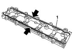
- Repeat the operation for all the valves.- Fit the tappet and rockers, respecting the marks made upon disassembly.- Repeat the operation for all rocker-tappet assemblies.1. Apply silicone sealant to the cylinder head extension mating surfaces.
Description
Qty.
Component
Type
Classification
.
DOW CORNING, 7091
-
CYLINDER HEAD EXTENSION
Silicone sealant
-
Engines: 2.0 JTD 8V
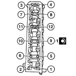
- Fit the cylinder head extension together with the camshaft.1. Tighten the twelve bolts (1a) to the specified torque in the order indicated.
Value - daNm
Fastening
Component
Ø
1
1,0
Bolt
CYLINDER HEAD EXTENSION FASTENERS
-
Engines: 2.0 JTD 8V
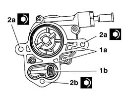
1. Lubricate and, if necessary, replace the seals (1a) and the oil filter (1b).2. Fit the vacuum unit and tighten the bolts (2a) and the nut (2b) to the recommended torque.
Value - daNm
Fastening
Component
Ø
2a
4,3
Bolt
BRAKING SYSTEM BRAKES
-
Value - daNm
Fastening
Component
Ø
2b
4,3
Nut
BRAKING SYSTEM BRAKES
-
Engines: 2.0 JTD 8V
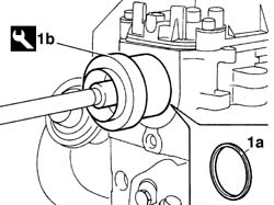
1. Fit the oil sealing ring (1a) using the tool (1b)
Description
Code
Function
1b
Fitting tool
1.860.990.000
Camshaft front oil seal
Engines: 2.0 JTD 8V
- Fit the camshaft pulley flange, centring the drive tooth.- Tighten the central flange retaining nut to the specified torque using the tool.
Description
Code
Function
.
Counter-torque
1.860.776.000
Timing pulley lock
Value - daNm
Fastening
Component
Ø
.
4,3
Nut
TIMING PULLEY FLANGE
-
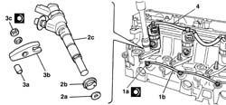
- Check spark plug continuity using a multimeter.1. Fit spark plugs (1a), tighten to the specified torque and fit spark plug supply lead (1b).
Value - daNm
Fastening
Component
Ø
1a
2,3
Spark plug
GLOW PLUGS
-
2. Fit the shim (2a), sealing ring (2b) and injector (2c) in order3. Fit support dowel (3a), bracket (3b) and tighten nut (3c) to the specified torque.
Value - daNm
Fastening
Component
Ø
3c
2,3
Nut
INJECTORS(DIESEL)
-
- Repeat the operation for all the injectors.4. Fit the fuel return pipe.
Engines: 2.8 JTD 8V
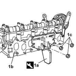
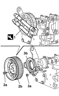
- Proceed with the DISMANTLING.- Place the head on a workbench.1. Fit the tool (1a) on the cylinder head (1b) and secure it using the nuts (1c), then place the tool (1a) in a vice.
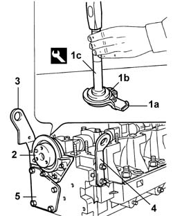
2. Undo the fixing bolts (2a) and remove the driven timing pulley (2b).3. Undo the fixing nuts (3a) and remove the front cover (3b).
Engines: 2.8 JTD 8V
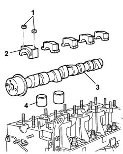
1. Undo the nuts fixing the camshaft caps.2. Remove the camshaft caps.3. Remove the camshaft.4. Remove the tappets.
Engines: 2.8 JTD 8V
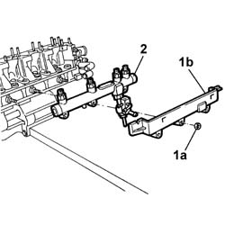
1. Undo the nuts (1a) and remove the fuel distribution manifold cover (1b).2. Remove the fuel distribution manifold.
Engines: 2.8 JTD 8V
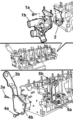
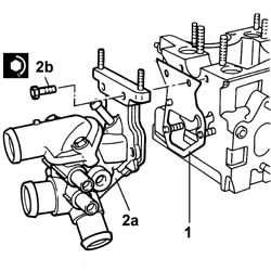
1. Undo the bolts (1a) and remove the thermostat unit (1b).2. Remove the seal.3. Undo the fixing bolts (3a) and remove the bracket (3b).4. Undo the fixing bolts (4a) and remove the cover (4b).5. Undo the fixing nuts (5a) and remove the bracket (5b).
Engines: 2.8 JTD 8V
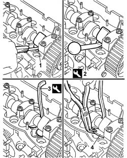
- Remove the cylinder head from the vice.- Position a suitable wooden stand on the cylinder head plane to support the valves and secure it using bolts.- Refit the cylinder head in the vice.1. Remove the cotters (1a) using the tool (1b).
Description
Code
Function
1b
Tool
1.860.644.000
Removing/refitting valves
2. Remove the valve upper shim.3. Remove the outer valve spring (3a) and the inner one (3b).
Engines: 2.8 JTD 8V
1. Remove the valve guide oil seal (1a) using the tool (1b).
Description
Code
Function
1b
Extractor
1.860.989.000
Valve guide oil seal extraction
2. Remove the lower shim.- Carry out the same operations on the other valves.- Remove the cylinder head from the vice.- Remove the wooden stand and keep the valves.- Remove the support tool from the cylinder head.
Description
Code
Function
.
Support
1.860.470.000
Cylinder head in vice
Engines: 2.8 JTD 8V
See in Op. 1016E14- Proceed with the REASSEMBLY- Clean any residues of the old gasket from the lower cylinder head plane.- Check that the planarity of the lower cylinder head plane corresponds to the recommended values.
Subject
Value
.
Cylinder head
mm
-
Lower plane planarity
0.1
1. If the planarity of the lower cylinder head plane does not correspond to the recommended figures, regrind it without exceeding the minimum permitted height.
Subject
Value
1
Cylinder head
mm
-
Minimum permitted height
149,5 - 149,7
Engines: 2.8 JTD 8V
- Check that the valves do not show signs of grooves or seizing.- Check that the diameter of the valve stems corresponds to the recommended figures; if not, replace the worn valves.
Subject
Value
.
Cylinder head valves (all)
mm
-
Stem diameter
7,985 - 8,000
See in Op. 1016E14- Check that the tappet outer diameter corresponds to the recommended figures; if not, replace the tappets with oversize ones.
Subject
Value
.
Cylinder head camshaft tappet cases
mm
-
Outer diameter
43,950 - 43,970
-
Outer diameter oversize
44,150 - 44,170
- Check that the diameter of the tappet housings corresponds to the recommended figures; if not, replace the cylinder head.
Subject
Value
.
Engine cylinder head
mm
-
Tappet housing diameter
44,000 - 44,025
-
Tappet housing diameter oversize
44,200 - 44,225
- Using a torque wrench, check that the spring specifications correspond to the recommended figures; if not, replace the worn components.
Subject
Value
.
Inner valve spring
-
Length mm
33,5
-
under a load of daN
15,4 - 17,4
Subject
Value
.
Inner valve spring
-
Length mm
23,5
-
under a load of daN
28,5 - 38,5
Subject
Value
.
Inner valve spring
-
Length mm
38,5
-
under a load of daN
41,3 - 46,3
Subject
Value
.
Inner valve spring
-
Length mm
28,5
-
under a load of daN
73,4 - 81,4
1. Reface the valve seats to the recommended figure using a suitable tool.
Subject
Value
1
Cylinder head valve seats (all)
-
Contact band angle with inlet valve
29° 55' - 30° 05'
-
Contact band angle with exhaust valve
44° 55' - 45° 05'
Subject
Value
2
Cylinder head valve seats (all)
-
Inlet/exhaust manifold outlet angle
20°
Subject
Value
3
Cylinder head valve seats (all)
-
Inlet/exhaust manifold inlet angle
75°
Engines: 2.8 JTD 8V
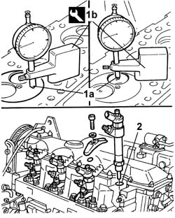
- Temporarily fit the injectors.1. Check that the injector projection in relation to the cylinder head plane (1a) corresponds to the recommended figures using the tool (1b) fitted with a dial gauge.
Subject
Value
.
Injectors (DIESEL)
mm
-
Projection from cylinder head plane
2,230 - 2,690
Description
Code
Function
1b
Dial gauge support
1.870.404.000
Injector projection from cylinder head plane measurement
2. If the projection of the injectors in relation to the cylinder head plane does not correspond to the recommended figures, fit an approriate oversize washer in the injector seat.
Engines: 2.8 JTD 8V
- Remove the injectors.- Temporarily fit the valves.1. Check that the valve recess in relation to the cylinder head plane (1a) corresponds to the recommended figures using the tool (1b) fitted with a dial gauge.
Subject
Value
1a
Cylinder head valves (all)
-
Valve recess in relation to cylinder head plane
mm
-
inlet
1,2 - 1,5
-
exhaust
1,0 - 1,3
Description
Code
Function
1b
Dial gauge support
1.870.404.000
Valve recess in cylinder head plane measurement
- If the valve recess in relation to the cylinder head plane does not correspond to the recommended figures, regrind the valve seats once again.
Engines: 2.8 JTD 8V
- Remove the valves.- Check that the nominal camshaft cam lift corresponds to the recommended figures; if not, replace the worn camshaft.
Subject
Value
.
INTAKE AND EXHAUST CAMSHAFT
-
Nominal cam lift
mm
-
inlet
9,5
-
exhaust
10,5
- Check that the diameter of the camshaft bearings corresponds to the recommended figures; if not, replace the worn camshaft with an oversize one.
Subject
Value
.
INTAKE AND EXHAUST CAMSHAFT
mm
-
Journal diameter
33,934 - 33,950
Subject
Value
.
INTAKE AND EXHAUST CAMSHAFT
mm
-
Journal diameter oversize
0,20
- Fit the camshaft caps (1a) on the cylinder head and tighten the nuts (1b) to the recommended torque.
Value - daNm
Fastening
Component
Ø
.
1,8
Nut
CAMSHAFT SUPPORTS
M8
- Check that the camshaft support diameter corresponds to the recommended figures; if not, proceed with the regrinding using the recommended oversize.
Subject
Value
.
Camshaft caps
mm
-
Support diameter
33,985 - 34,015
Subject
Value
.
Camshaft caps
mm
-
Support diameter oversize
0,20
- Fit the support tool on the cylinder head and secure it using the nuts.
Description
Code
Function
.
Support
1.860.470.000
Cylinder head in vice
- Fit all the valves.- Position a suitable wooden stand on the cylinder head plane to support the valves and secure it using bolts.- Fit the cylinder head, complete with valves, in the vice.- Fit the lower shim.1. Fit the valve guide oil seal (1a) using the tool (1b).
Description
Code
Function
1b
Fitting tool
1.860.313.000
Valve guide oil seal fitting.
Engines: 2.8 JTD 8V
1. Fit the inner valve spring (1a) and the outer one (1b).2. Fit the valve upper shim.3. Fit the cotters (3a) using the tool (3b).
Description
Code
Function
3b
Tool
1.860.644.000
Removing/refitting valves
Engines: 2.8 JTD 8V
- Carry out the same operations on the other valves.- Remove the cylinder head from the vice.- Remove the wooden stand supporting the valves.- Refit the cylinder head in the vice.- Fit the tappets complete with valve clearance adjustment pads.- Fit the camshaft.1. Fit the camshaft caps.2. Tighten the camshaft cap bolts to the recommended torque.
Value - daNm
Fastening
Component
Ø
.
1,8
Nut
CAMSHAFT SUPPORTS
M8
Engines: 2.8 JTD 8V
1. Fit the front oil seal on the camshaft cover (1a) using the tools (1b) and (1c).
Description
Code
Function
1b
Fitting tool
1.860.623.000
Camshaft front oil seal fitting
Description
Code
Function
1c
Grip
1.870.007.000
Camshaft front oil seal fitting
2. Fit the front cover applying sealant and tighten the fixing nuts to the recommended torque.
Value - daNm
Fastening
Component
Ø
2
0.75
Nut
INLET AND EXHAUST CAMSHAFT FRONT COVER
M6
3. Fit the bracket tightening the fixing nuts.4. Fit the cover applying sealant and tightening the fixing bolts.5. Fit the bracket tightening the fixing nuts.
Engines: 2.8 JTD 8V
- Fit the tool.
Description
Code
Function
.
Counter-torque
1.860.765.001
Loosen/tighten toothed timing drive pulley bolt
- Fit the toothed driven pulley and tighten the fixing bolts to the recommended torque.
Value - daNm
Fastening
Component
Ø
.
2,5
Bolt
TIMING DUCT PULLEY
M8
- Remove the tool.
Description
Code
Function
.
Counter-torque
1.860.765.001
Loosen/tighten toothed timing drive pulley bolt
1. Check that the valve clearance, with the valves closed, corresponds to the recommended figures; if not, replace the valve clearance adjustment pads following the instructions given below.
Subject
Value
.
Cylinder head valves (all)
-
Inlet valves clearance in closed position
mm
-
inlet
0,45 - 0,55
-
exhaust
0,45 - 0,55
2. Lower the tappet in question using the tool.
Description
Code
Function
2
Lever
1.860.443.000
Lower tappets
3. Fit the tool.
Description
Code
Function
3
Lever
1.860.724.001
Keep tappets lowered
- Remove the tool.
Description
Code
Function
.
Lever
1.860.443.000
Lower tappets
4. Remove the valve clearanance adjustment plate and replace it with a one of a suitable thickness.- Remove the tool.
Description
Code
Function
.
Lever
1.860.724.001
Keep tappets lowered
Engines: 2.8 JTD 8V
1. Remove the seal.2. Fit the thermostat (2a) complete with pipes and tighten the bolts (2b) to the recommended torque.
Value - daNm
Fastening
Component
Ø
2b
1,8
Bolt
THERMOSTAT
M8
Engines: 2.8 JTD 8V
- Fit the fuel distribution manifold complete with pipes and fuel pressure sensor and tighten the nuts.- Remove the cylinder head from the vice.- Remove the support tool from the cylinder head.