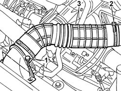
- Position the vehicle on the lift. Op. 7055B54 UNDER-ENGINE GUARD - R R1. Undo the bolts fixing the cold air intake to the upper crossmember.2. Disconnect the intake hose from the air filter casing.3. Remove the cold intake and intake hose assembly from the engine compartment.
Engines: 2.3 JTD 16V
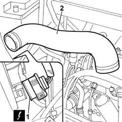
1. Remove the air delivery sleeve to the air-air heat exchanger (intercooler).
Engines: 2.3 JTD 16V
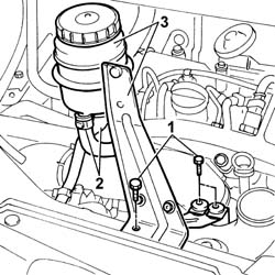
- Draw off the fluid inside the power steering fluid reservoir with a syringe.1. Undo the bolts securing the power steering fluid reservoir bracket.2. Disconnect both fluid pipes from the reservoir and plug with plugs of appropriate size.3. Remove the power assisted steering fluid reservoir, complete with bracket, from the housing.
Engines: 2.3 JTD 16V
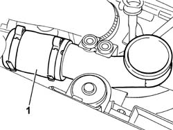
1. Remove the second section of the air delivery sleeve to the air-air heat exchanger (intercooler).
Engines: 2.3 JTD 16V
1. Disconnect the right front light cluster electrical connection.
Description
Connector
1
Right headlamp
F011
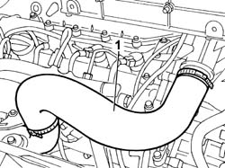
2. Disconnect the collars at both ends and remove the air hose from intercooler to intake manifold.
Engines: 2.3 JTD 16V
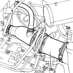
1. Disconnect the band fastening the air supply hose to the turbocharger.2. Disconnect the vapour recovery pipe from the air supply hose to the turbocharger.3. Disconnect the collar from turbocharger (3a) and remove the air delivery sleeve to turbocharger (3b).
Engines: 2.3 JTD 16V
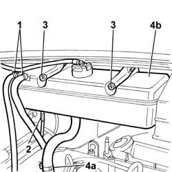
1. Disconnect the bands retaining the coolant pipe to the reservoir.2. Disconnect the electrical connection from the coolant reservoir.3. Undo the nuts fixing the expansion tank.4. Disconnect pipe (4a) carrying fluid to the coolant pump and remove expansion tank (4b).
Engines: 2.3 JTD 16V
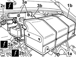
1. Undo the fixing bolts (1a) and remove the protective cover (1b) for the heater plugs control unit.2. Disconnect the electrical connections for the heater plugs control unit (2a) and (2b) and the control unit positive electrical connection (2c).
Description
Connector
2a
Heater plugs control unit
M015A
Description
Connector
2b
Heater plugs control unit
M015B
Description
Connector
2c
Heater plugs control unit
M015C
3. Undo the fixing nuts (3a) and remove the mounting bracket (3b) complete with heater plugs control unit.
Engines: 2.3 JTD 16V
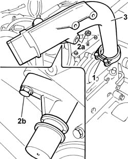
1. Loosen the bolt fixing the collar joining the rigid section of the intake pipe to the turbocharger.2. Undo the nuts (2a) fixing the pipe to the bracket on the cylinder head and the bolt (2b) fixing the connector for the engine oil vapour pipe.3. Remove the rigid section of the air pipe from the turbocharger.
Engines: 2.3 JTD 16V
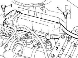
1. Undo the retaining bolts.2. Remove the engine oil vapour separator.
Engines: 2.3 JTD 16V
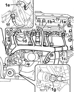
1. Disconnect the electrical connections:
Description
Connector
1a
Injector
N070A
Description
Connector
1a
Injector
N070B
Description
Connector
1a
Injector
N070C
Description
Connector
1a
Injector
N070D
Description
Connector
1b
Fuel pressure sensor
K083
Description
Connector
1c
Air pressure - temperature sensor
K044
Description
Connector
.
Heater plugs
A040A
Description
Connector
.
Heater plugs
A040B
Description
Connector
.
Heater plugs
A040C
Description
Connector
.
Heater plugs
A040D
Description
Connector
1d
Timing sensor
K047
Description
Connector
1e
Coolant temperature sending unit (for instrument panel)
K035
Description
Connector
1f
Engine coolant temperature sensor/sender unit
K036
Description
Connector
1g
Fuel pressure regulator
N077
- Release the wiring from the bands and move it to the side.
Engines: 2.3 JTD 16V
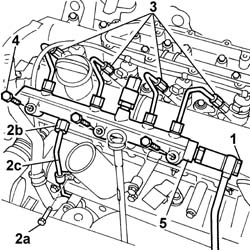
1. Unscrew the fitting of the return pipe to the return manifold.2. Undo the fixing bolt (2a), undo the connector (2b) and disconnect the supply pipe (2c) from the pump to the fuel manifold.3. Undo the connectors for the supply pipes from the manifold to the injectors.4. Undo the bolts fixing the fuel manifold to the camshaft housing.5. Remove the fuel manifold complete with supply pipes to the injectors.
Engines: 2.3 JTD 16V
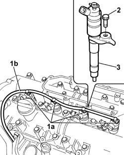
1. Press the fastening springs (1a) and disconnect the fuel recirculation pipe (1b) from the injectors.2. Undo the bolts fixing the brackets.3. Use the extractor and driver to remove the injectors from their seats on the cylinder head extension.
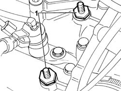
1. Undo the studs on the camshaft housing and remove them.
Engines: 2.3 JTD 16V
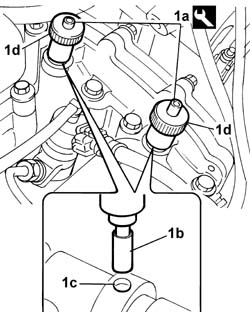
1. Fit camshaft timing tools (1a) and insert until the cylindrical part of the tool is fully fitted into hole (1c) on the camshaft. Secure the tool in place tightening the tool ring nuts (1d).
Description
Code
Function
1a
Templates
99360614
Camshaft timing adjustment
Engines: 2.3 JTD 16V
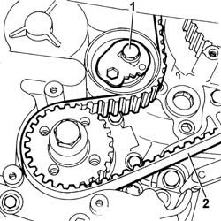
1. Undo the nut fixing the timing drive belt tensioner.2. Remove the timing belt.
Engines: 2.3 JTD 16V
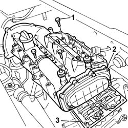
1. Undo the retaining bolts.2. Remove the cylinder head extension complete with camshafts.3. Remove the underlying gasket.
- Fit a new gasket to the cylinder head.- Fit the cylinder head extension complete with camshafts and camshaft timing tools.- Tighten the bolts securing the cylinder head extension to the cylinder head to torque.
Value - daNm
Fastening
Component
Ø
.
11,5
Bolt
CYLINDER HEAD EXTENSION
M12X1.25
Value - daNm
Fastening
Component
Ø
.
1
Bolt
CYLINDER HEAD EXTENSION
M6
Value - daNm
Fastening
Component
Ø
.
2.5
Bolt
CYLINDER HEAD EXTENSION
M8X1.25
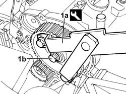
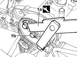
1. Use reaction tool (1a) fitted with pins to unscrew timing pulley bolt (1b).
Description
Code
Function
1a
Counter-torque
1.870.815.000
Timing pulley lock
Description
Code
Function
1a
Pins for counter-torque
1.870.836.000
Timing pulley lock
Engines: 2.3 JTD 16V
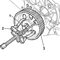
1. Position a hexagonal bolt in the housing for the pulley fixing bolt.2. Position the USAG 452/1 universal extractor and tighten the extractor pin until it is in contact with the bolt positioned previously.3. Continue tightening the tool pin until the camshaft pulley is extraected.
Engines: 2.3 JTD 16V
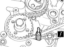
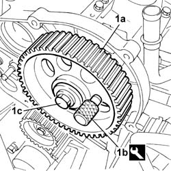
1. Refit the timing pulley (1a) in the housing on the shaft, position the pin (1b) for timing the pulley in relation to the timing sensor, then lock the bolt (1c) fixing the pulley to the shaft.
Description
Code
Function
1b
Pin for timing adjustment
1.860.617.000
Positioning of timing pulley with timing sensor
Engines: 2.3 JTD 16V
1. Rotate the moving tensioner to the position illustrated to facilitate the fitting of the timing belt.
Engines: 2.3 JTD 16V
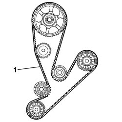
1. Fit the timing belt onto the pulleys and gears.
Engines: 2.3 JTD 16V
- Remove the timing pin for the timing pulley in relation to the timing sensor.
Description
Code
Function
.
Pin for timing adjustment
1.860.617.000
Positioning of timing pulley with timing sensor
1. Using the reaction tool (1a) fitted with pins, tighten the bolt fixing the timing drive pulley (1a) to torque.
Description
Code
Function
1a
Counter-torque
1.870.815.000
Timing pulley lock
Description
Code
Function
1a
Pins for counter-torque
1.870.836.000
Timing pulley lock
Engines: 2.3 JTD 16V
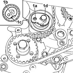
1. Acting on the hexagonal bolt (1a), rotate the semi-automatic tensioner in an anti-clockwise direction, placing the tensioner (1b) moving reference in the position illustrated, i.e. about 20°-22° to the right of the position indicated by the reference (1c), then lock the fixing nut (1d).
Engines: 2.3 JTD 16V
- Tighten the bolt fixing the automatic tensioner.- Remove the tools used for timing the camshafts and for positioning the crankshaft at T.D.C.
Description
Code
Function
.
Templates
99360614
Camshaft timing adjustment
Description
Code
Function
.
Pin
99360615
TDC positioning
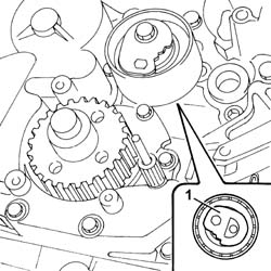
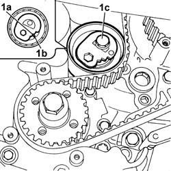
- Rotate the crankshaft through eight revolutions in its direction of rotation.1. Loosen the bolt fixing the tensioner and, working carefully, position the tensioner (1a) reference in line with the reference opening (1b), then tighten the nut (1c) fixing the belt tensioner to torque.
Value - daNm
Fastening
Component
Ø
1c
3.6
Bolt
MOBILE TIMING TENSIONER
M8
Engines: 2.3 JTD 16V
- Rotate the crankshaft through two further revolutions in its direction of rotation.- Check that the position of the references remains unchanged, then temporarily refit the tools for timing the camshafts and the crankshaft for a final check.- If the tools do not fit perfectly in the housings or the references on the tensioner have moved, carry out the belt tension adjustment procedure again.- Fit the studs on the head extension. See in Op. 1032D12 See in Op. 1092A10 Op. 1092B72 POWER STEERING PUMP DRIVE BELT - ALTERNATOR - R&R Op. 4450B04 RIGHT FRONT WHEEL R R- Lower the vehicle.- Fit the injectors in the seats in the camshaft housing.- Tighten the bolts fixing the brackets.
Value - daNm
Fastening
Component
Ø
.
2.5
Bolt
INJECTORS(DIESEL)
M8
- Fasten the recirculation pipe on the injectors using securing bands.- Fit the fuel manifold complete with supply pipes to the injectors.- Tighten the bolts fixing the fuel manifold to torque.
Value - daNm
Fastening
Component
Ø
.
2.5
Bolt
INJECTOR FUEL MANIFOLD (DIESEL)
M8
- Tighten the connectors for the pipes on the injectors to torque.
Value - daNm
Fastening
Component
Ø
.
2.3
Connectors
INJECTOR FUEL MANIFOLD PIPE
M12X1.5
- Tighten the connector for the fuel supply pipe from the pressure pump to torque.
Value - daNm
Fastening
Component
Ø
.
2.3
Connector
PRESSURE PUMP LINE TO FUEL MANIFOLD
M14
- Tighten the bolt fixing the fuel supply pipe from the pressure pump to the bracket.- Screw in the connector for the return pipe from the single fuel manifold to the return manifold and tighten it to torque.
Value - daNm
Fastening
Component
Ø
.
4
Connector
INJECTOR FUEL MANIFOLD (DIESEL)
M16
- Position the injection wiring and connect the electrical connections disconnected previously.
Description
Connector
Injector
N070A
Description
Connector
Injector
N070B
Description
Connector
Injector
N070C
Description
Connector
Injector
N070D
Description
Connector
Fuel pressure sensor
K083
Description
Connector
Air pressure - temperature sensor
K044
Description
Connector
.
Heater plugs
A040A
Description
Connector
.
Heater plugs
A040B
Description
Connector
.
Heater plugs
A040C
Description
Connector
.
Heater plugs
A040D
Description
Connector
Timing sensor
K047
Description
Connector
Coolant temperature sending unit (for instrument panel)
K035
Description
Connector
Engine coolant temperature sensor/sender unit
K036
Description
Connector
Fuel pressure regulator
N077
- Fit the vapour separator in the seat in the camshaft housing and tighten the fixing bolts.
Value - daNm
Fastening
Component
Ø
.
1
Bolts
ENGINE OIL VAPOUR SEPARATOR
M6
- Fit the rigid section of the air pipe from the turbocharger and tighten the bolt fixing the collar.- Tighten the bolts fixing it to the cylinder head.- Tighten the bolt fixing the engine oil vapour pipe.- Fit the mounting bracket complete with heater plugs control unit.- Tighten the nuts fixing the control unit to the bodyshell.- Connect the electrical connections for the heater plugs control unit.
Description
Connector
.
Heater plugs control unit
M015A
Description
Connector
.
Heater plugs control unit
M015B
Description
Connector
.
Heater plugs control unit
M015C
- Fit the protective cover for the heater plugs control unit and tighten the bolts fixing it to the mounting bracket underneath.- Fit the engine coolant reservoir and tighten the nuts fixing it to the bodyshell.- Connect the coolant delivery pipe to the pump.- Fasten the electrical connection in the housing on the tank.- Connect the bands retaining the coolant pipes to the cylinder head and the radiator.- Fit the air delivery sleeve to the turbocharger to the air cleaner case.- Connect to the turbocharger and air cleaner case.- Connect the engine oil vapour separator pipe to the fitting.- Fit the air hose from intercooler to intake manifold.- Connect the right front light cluster electrical connection.
Description
Connector
.
Right headlamp
F011
- Fit the second section of the air delivery sleeve to the air-air heat exchanger (intercooler).- Fit the power steering fluid reservoir complete with bracket.- Connect the oil hoses to the reservoir and tighten the power steering fluid reservoir bracket bolts to the beam.- Fit the air delivery sleeve to the air-air heat exchanger (intercooler).- Fit the cold intake and intake hose assembly in the engine compartment and tighten the bolts fixing the cold air intake to the upper headlamp holder crossmember.- Connect the intake hose to the air filter casing. Op. 0010T21 COOLANT CHECK DENSITY AND TOP UP IF NECESSARY Op. 7055B54 UNDER-ENGINE GUARD - R R