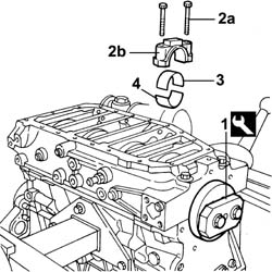
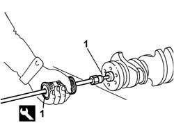
- Rotate the crankshaft using the tool fitted previously until the cylinder concerned is at B.D.C.2. Undo the bolts (2a) and remove the connecting rod cap (2b).3. Remove the lower connecting rod half-bearing.4. Remove the upper connecting rod half-bearing.- Carry out the same operations to remove the connecting rod half-bearings for the remaining cylinders.- Remove the tool.
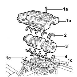
1. Undo the bolts (1a) and remove the lower crankcase (1b) and the gasket (1c).2. Remove the lower main journal half-bearings.3. Remove the crankshaft.4. Remove the upper main journal half-bearings.
- Check that there are no deposits or blockages in the crankshaft lubrication ducts.- Check the static balance of the crankshaft resting the main journals on suitable parallels.- Check that the diameter of the main journals corresponds to the recommended figures.
Subject
Value
.
Crankshaft
mm
-
Main journal diameter
80,182 - 80,208
-
Main journal diameter
86,182- 86,208 (*)
- (*) main journal n°5- If the diameter of the main journals is not correct, they should be reground to the recommended undersize.
Subject
Value
.
Crankshaft
mm
-
Main journal undersize
0,254 - 0,508
- Check that the diameter of the crankpins corresponds to the recommended figures.
Subject
Value
.
Crankshaft
mm
-
Crankpin diameter
56,515 - 56,538
- If the diameter of the crankpins is not correct, they should be reground to the recommended undersize.
Subject
Value
.
Crankshaft
mm
-
Crankpin undersize
0,254 - 0,508
Subject
Value
.
Crankshaft
mm
-
Ovality
0,005
-
Taper
0,005
Subject
Value
.
Crankshaft
mm
-
Main journal misalignment
0,05
-
Crankpin misalignment
0,125
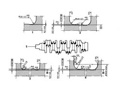
1. Regrind the shaft following the recommended figures.
- Visually inspect the condition of the main journal and crankpin half-bearings and replace them if necessary.- Check that the thickness of the half-bearings corresponds to the recommended figures; if not, replace them.
Subject
Value
.
Main bearing half thickness
mm
-
Category A
2,165 - 2,174
-
Category B
2,319 - 2,428
-
Category C
2,573 - 2,682
- Check that the thickness of the half-bearings corresponds to the recommended figures; if not, replace them.
Subject
Value
.
Connecting rod bearing half thickness
mm
-
Category A
1,875 - 1,884
-
Category B
2,129 - 2,138
-
Category C
2,483 - 2,492
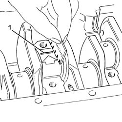
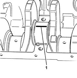
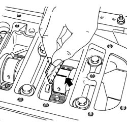
- Fit the upper main journal half-bearings in the cylinder block/crankcase.- Fit the crankshaft in the crankcase.1. Fit the calibrated wire (plastigate) for measuring the bearing clearance.
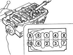
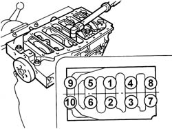
- Position the gaskets and the lower main journal half-bearings on the lower crankcase.- Fit the lower crankcase.1. Tighten the bolts fixing the lower crankcase to the recommended torque in the order given.
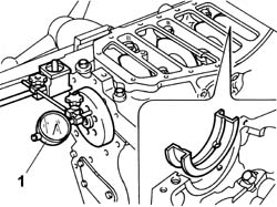
- If the crankshaft endfloat does not correspond to the recommended figure, the crankshaft must be reground and the crankshaft half-bearings replaced as a result.- Fit the lower crankcase complete with half-bearings.1. Tighten the bolts fixing the lower crankcase to the recommended torque in the order given.
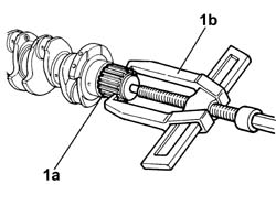
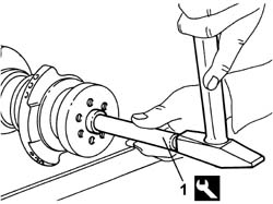
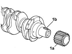
- Heat the timing gear in the oven letting it reach a temperature 20°C higher than the crankshaft.1. fit the timing gear (1a) ensuring that the groove coincides with the key (1b).
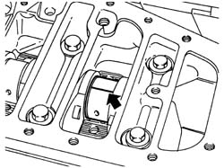
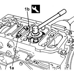
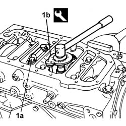
- Fit the upper connecting rod half-bearings on the big end.- Rotate the crankshaft until cylinders no.1 and 4 are at B.D.C.- Fit the connecting rod caps complete with the half-bearings for cylinders no. 1 and 4 and secure them without tightening the bolts.- Proceed in the same way to fit the 2nd and 3rd cylinder connecting rod caps.1. Tighten the bolts (1a) to the recommended torque, using the angular tightening tool (1b).
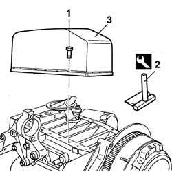
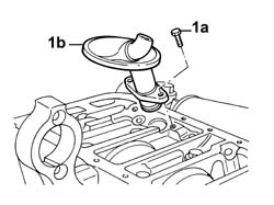
- Fit the engine oil intake and tighten the fixing bolts.- Apply silicon sealant to the entire perimeter of the crankcase sump.
Description
Qty.
Component
Type
Classification
.
Dow Corning 7091
-
OIL SUMP
Silicone sealant
-
- Fit the crankcase sump.- Tighten the bolts fixing the crankcase sump to the recommended torque.
Value - daNm
Fastening
Component
Ø
.
1,8
Bolt
OIL SUMP
M8
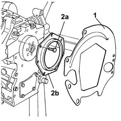
See in Op. 1020D13- Fit the protective cover.- Fit the crankcase rear cover with the oil seal incorporated and tighten the fixing bolts to the recommended torque.
Value - daNm
Fastening
Component
Ø
.
(engine crankcase side) 2.5
Bolt
REAR COVER CRANKSHAFT
M8
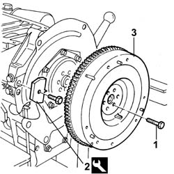
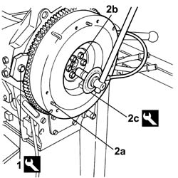
1. Fit the tool.
Description
Code
Function
1
Counter-torque
1.860.741.000
Tool for preventing crankshaft rotation
2. Fit the flywheel (2a), apply thread-locking agent to the bolts (2b) and tighten them to the recommended torque using the angular tightening tool (2c).
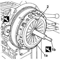
2. - Tighten the fixing bolts to the recommended torque.
Value - daNm
Fastening
Component
Ø
2
(Engine crankshaft side) 13.6 -16.8
Bolt
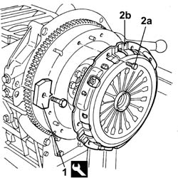
CLUTCH ASSEMBLY
M12
3. Remove the tool.
Description
Code
Function
3
Counter-torque
1.860.741.000
Tool for preventing crankshaft rotation
Engines: 2.3 JTD 16V
- Proceed with positioning the engine on the rotary overhaul stand.- Proceed with the removal of all the components connected to the lower crankcase and to the cylinder head.- Remove the lower crankcase and the crankshaft.- These operations are described in the following procedures: See in Op. 1004D40 See in Op. 1004E10 See in Op. 1004E20