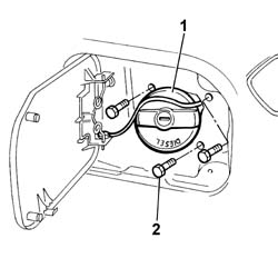
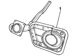
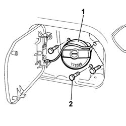
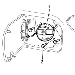
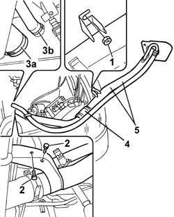
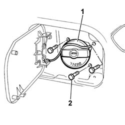
1. Remove the fuel filler cap.2. Undo the bolts fixing the fuel filler pipe to the bodyshell.
Engines: 2.0 16V
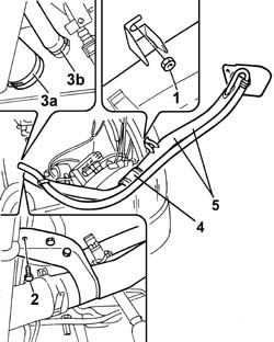
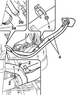
1. Undo the fixing nut located under the brake servo.- Release the filler pipe from the bands securing the electrical wiring.- Raise the lift. Op. 7055B54 UNDER-ENGINE GUARD - R R2. Undo the lower bolts fixing the filler pipe to the bodyshell.3. Disconnect the flexible section of the fuel filler pipe (3a) and the reflux pipe (3b) from the tank.- Lower the lift.4. Separate the two sections of the pipe working on the retaining band.5. Remove the pipe in two sections.
Engines: 2.0 16V
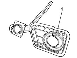
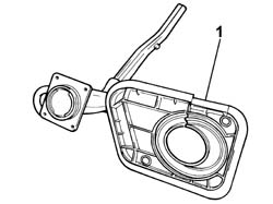
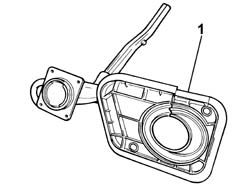
1. With the filler pipe at the bench, remove the filler internal plastic protection.
Engines: 2.0 16V
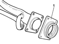
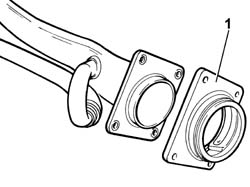
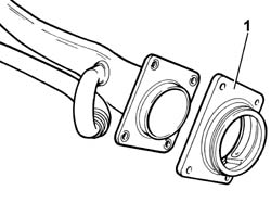
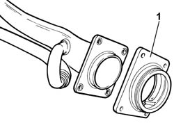
1. Remove the plate with the threaded connector for the fuel cap from the filler pipe.
- Fit the plate with the threaded connector for the fuel cap on the filler pipe.- Fit the filler internal plastic protection.- Fit the tank section of the fuel filler pipe and then connect the next section securing them with the retaining band.- Raise the lift.- Connect the flexible section of the fuel filler pipe (3a) and the reflux pipe (3b) to the tank.- Tighten the lower bolts fixing the filler pipe to the bodyshell. Op. 7055B54 UNDER-ENGINE GUARD - R R- Lower the lift.- Secure the electrical wiring to the filler pipe.- Tighten the fixing nut located under the brake servo.- Tighten the bolts fixing the fuel filler pipe to the bodyshell.- Secure the wiring to the filler pipe.- Fit the junction unit mounting bracket.- Fit the engine compartment junction unit mounting and tighten the fixing nuts. Op. 5505A13 SUPPLEMENTARY JUNCTION CONTROL UNIT IN ENGINE BAY - R R See in Op. 1048A10- Connect the negative battery terminal.- Remove the vehicle from the lift.
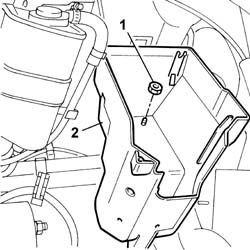
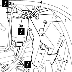
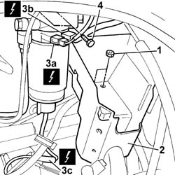
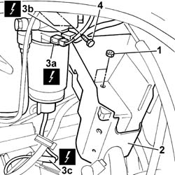
- Position the vehicle on a lift.- Disconnect the negative battery terminal. See in Op. 1048A10 Op. 5505A13 SUPPLEMENTARY JUNCTION CONTROL UNIT IN ENGINE BAY - R R See in Op. 1040A401. Undo the fixing nuts.2. Remove the support for the engine compartment junction unit.3. Disconnect the electrical connections (3a), (3b) and (3c) for the fuel filter.
Description
Connector
3a
Fuel temperature sensor
K081
Description
Connector
3b
Diesel heating resistance
O020
Description
Connector
3c
Water in diesel filter sensor
K031
4. Undo the bolts fixing the fuel filter to the bodyshell.
Engines: 2.3 JTD 16V
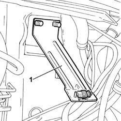
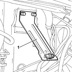
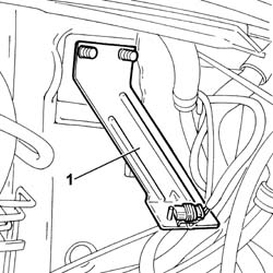
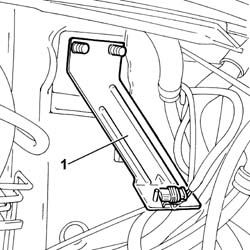
1. Remove the junction unit mounting bracket.
Engines: 2.3 JTD 16V
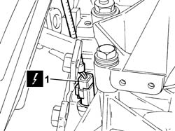
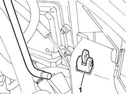
1. Disconnect the electrical connection for the reversing light switch.
Description
Connector
1
Reversing lights switch
I020
- Release the wiring from the filler pipe.
Engines: 2.3 JTD 16V
1. Remove the fuel filler cap.2. Undo the bolts fixing the fuel filler pipe to the bodyshell.
Engines: 2.3 JTD 16V
1. Undo the fixing nut located under the brake servo.- Release the filler pipe from the bands securing the electrical wiring.- Raise the lift. Op. 7055B54 UNDER-ENGINE GUARD - R R2. Undo the lower bolts fixing the filler pipe to the bodyshell.3. Disconnect the flexible section of the fuel filler pipe (3a) and the reflux pipe (3b) from the tank.- Lower the lift.4. Remove the fuel filler pipe assembly.
Engines: 2.3 JTD 16V
1. With the filler pipe at the bench, remove the filler internal plastic protection.
Engines: 2.3 JTD 16V
1. Remove the plate with the threaded connector for the fuel cap from the filler pipe.
- Fit the plate with the threaded connector for the fuel cap on the filler pipe.- Fit the filler internal plastic protection.- Fit the fuel filler pipe assembly.- Raise the lift.- Connect the flexible section of the fuel filler pipe (3a) and the reflux pipe (3b) to the tank.- Tighten the lower bolts fixing the filler pipe to the bodyshell. Op. 7055B54 UNDER-ENGINE GUARD - R R- Lower the lift.- Secure the electrical wiring to the filler pipe.- Tighten the fixing nut located under the brake servo.- Tighten the bolts fixing the fuel filler pipe to the bodyshell.- Connect the electrical connection for the reversing light switch.
Description
Connector
.
Reversing lights switch
I020
- Secure the wiring to the filler pipe.- Fit the junction unit mounting bracket.- Tighten the nuts fixing the fuel filter to the bodyshell to torque.
Value - daNm
Fastening
Component
Ø
.
(body) 3.5
Nuts
FUEL FILTER
M10
- Connect the electrical connections for the fuel filter.
- Position the vehicle on a lift.- Disconnect the negative battery terminal. See in Op. 1048A10 Op. 5505A13 SUPPLEMENTARY JUNCTION CONTROL UNIT IN ENGINE BAY - R R See in Op. 1040A402. Remove the support for the engine compartment junction unit.3. Disconnect the electrical connections (3a), (3b) and (3c) for the fuel filter.
Description
Connector
3a
Fuel temperature sensor
K081
Description
Connector
3c
Water in diesel filter sensor
K031
Description
Connector
3b
Diesel heating resistance
O020
4. Undo the bolts fixing the fuel filter to the bodyshell.
Engines: 2.0 JTD 8V
1. Remove the junction unit mounting bracket.
Engines: 2.0 JTD 8V
1. Remove the fuel filler cap.2. Undo the bolts fixing the fuel filler pipe to the bodyshell.
Engines: 2.0 JTD 8V
1. Undo the fixing nut located under the brake servo.- Release the filler pipe from the bands securing the electrical wiring.- Raise the lift. Op. 7055B54 UNDER-ENGINE GUARD - R R2. Undo the lower bolts fixing the filler pipe to the bodyshell.3. Disconnect the flexible section of the fuel filler pipe (3a) and the reflux pipe (3b) from the tank.- Lower the lift.4. Separate the two sections of the pipe working on the retaining band.5. Remove the pipe in two sections.
Engines: 2.0 JTD 8V
1. With the filler pipe at the bench, remove the filler internal plastic protection.
Engines: 2.0 JTD 8V
1. Remove the plate with the threaded connector for the fuel cap from the filler pipe.
- Fit the plate with the threaded connector for the fuel cap on the filler pipe.- Fit the filler internal plastic protection.- Fit the tank section of the fuel filler pipe and then connect the next section securing them with the retaining band.- Raise the lift.- Connect the flexible section of the fuel filler pipe (3a) and the reflux pipe (3b) to the tank.- Tighten the lower bolts fixing the filler pipe to the bodyshell. Op. 7055B54 UNDER-ENGINE GUARD - R R- Lower the lift.- Secure the electrical wiring to the filler pipe.- Tighten the fixing nut located under the brake servo.- Tighten the bolts fixing the fuel filler pipe to the bodyshell.- Secure the wiring to the filler pipe.- Fit the junction unit mounting bracket.- Tighten the nuts fixing the fuel filter to the bodyshell to torque.
Value - daNm
Fastening
Component
Ø
.
(body) 3.5
Nuts
FUEL FILTER
M10
- Connect the electrical connections for the fuel filter.
- Position the vehicle on the lift.- Disconnect the negative battery terminal. See in Op. 1048A10 Op. 5505A13 SUPPLEMENTARY JUNCTION CONTROL UNIT IN ENGINE BAY - R R See in Op. 1040A401. Undo the fixing nuts.2. Remove the support for the engine compartment junction unit.3. Disconnect the electrical connections (3a), (3b) and (3c) for the fuel filter.
Description
Connector
3a
Fuel temperature sensor
K081
Description
Connector
3c
Water in diesel filter sensor
K031
Description
Connector
3b
Diesel heating resistance
O020
4. Undo the bolts fixing the fuel filter to the bodyshell.
Engines: 2.8 JTD 8V
1. Remove the junction unit mounting bracket.
Engines: 2.8 JTD 8V
1. Remove the fuel filler cap.2. Undo the bolts fixing the fuel filler pipe to the bodyshell.
Engines: 2.8 JTD 8V
1. Undo the fixing nut located under the brake servo.- Release the filler pipe from the bands securing the electrical wiring.- Raise the lift. Op. 7055B54 UNDER-ENGINE GUARD - R R2. Undo the lower bolts fixing the filler pipe to the bodyshell.3. Disconnect the flexible section of the fuel filler pipe (3a) and the reflux pipe (3b) from the tank.- Lower the lift.4. Separate the two sections of the pipe working on the retaining band.5. Remove the pipe in two sections.
Engines: 2.8 JTD 8V
1. With the filler pipe at the bench, remove the filler internal plastic protection.
Engines: 2.8 JTD 8V
1. Remove the plate with the threaded connector for the fuel cap from the filler pipe.
- Fit the plate with the threaded connector for the fuel cap on the filler pipe.- Fit the filler internal plastic protection.- Fit the tank section of the fuel filler pipe and then connect the next section securing them with the retaining band.- Raise the lift.- Connect the flexible section of the fuel filler pipe (3a) and the reflux pipe (3b) to the tank.- Tighten the lower bolts fixing the filler pipe to the bodyshell. Op. 7055B54 UNDER-ENGINE GUARD - R R- Lower the lift.- Secure the electrical wiring to the filler pipe.- Tighten the fixing nut located under the brake servo.- Tighten the bolts fixing the fuel filler pipe to the bodyshell.- Secure the wiring to the filler pipe.- Fit the junction unit mounting bracket.- Tighten the nuts fixing the fuel filter to the bodyshell to torque.
Value - daNm
Fastening
Component
Ø
.
(body) 3.5
Nuts
FUEL FILTER
M10
- Connect the electrical connections for the fuel filter.