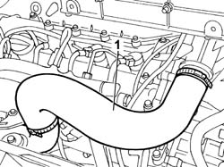
- Position the vehicle on the lift.1. Remove the air supply hose to the air/air heat exchanger (intercooler).
Engines: 2.3 JTD 16V
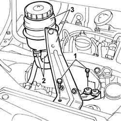
1. Undo the bolts fixing the power assisted steering fluid reservoir mounting bracket.2. Disconnect the fluid pipes from the reservoir.3. Remove the power assisted steering fluid reservoir complete with bracket.
Engines: 2.3 JTD 16V
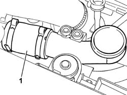
1. Remove the second section of the air supply hose to the air/air heat exchanger (intercooler).
Engines: 2.3 JTD 16V
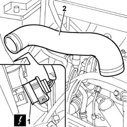
1. Disconnect the electrical connection for the right front light cluster.
Description
Connector
.
Right headlamp
F011
2. Disconnect the bands at the two ends and remove the air pipe from the air/air heat exchager to the intake manifold.
Engines: 2.3 JTD 16V
1. Disconnect the electrical connections:
Description
Connector
Injector
N070A
Description
Connector
Injector
N070B
Description
Connector
Injector
N070C
Description
Connector
Injector
N070D
Description
Connector
Fuel pressure sensor
K083
Description
Connector
Air pressure - temperature sensor
K044
Description
Connector
.
Heater plugs
A040A
Description
Connector
.
Heater plugs
A040B
Description
Connector
.
Heater plugs
A040C
Description
Connector
.
Heater plugs
A040D
Description
Connector
Timing sensor
K047
Description
Connector
Fuel pressure regulator
N077
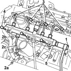
- Release the wiring from the bands and move it sideways.1. Undo the connector for the supply pipe from the pressure pump to the return manifold2. Undo the fixing bolt (2a), undo the connector (2b) and disconnect the supply pipe (2c) from the pump to the fuel manifold.3. Undo the connectors for the supply pipes from the manifold to the injectors.4. Undo the bolts fixing the fuel manifold to the camshaft housing.5. Remove the fuel manifold complete with supply pipes to the injectors.
- Fit the fuel manifold complete with supply pipes to the injectors.- Tighten the bolts fixing the fuel manifold to torque.
Value - daNm
Fastening
Component
Ø
.
2.5
Bolt
INJECTOR FUEL MANIFOLD (DIESEL)
M8
- Tighten the connectors for the pipes on the injectors to torque.
Value - daNm
Fastening
Component
Ø
.
2.3
Connectors
INJECTOR FUEL MANIFOLD PIPE
M12X1.5
- Tighten the connector for the fuel supply pipe from the pressure pump to torque.
Value - daNm
Fastening
Component
Ø
.
2.3
Connector
PRESSURE PUMP LINE TO FUEL MANIFOLD
M14
- Tighten the bolt fixing the fuel supply pipe from the pressure pump to the bracket.- Screw in the connector for the return pipe from the single fuel manifold to the return manifold and tighten it to torque.
Value - daNm
Fastening
Component
Ø
.
4
Connector
INJECTOR FUEL MANIFOLD (DIESEL)
M16
- Tighten the bolts fixing the power assisted steering fluid reservoir mounting bracket.- Fit the air supply hose to the air/air heat exchanger (intercooler).- Remove the vehicle from the lift.- Position the injection wiring and connect the electrical connections disconnected previously.
Description
Connector
Injector
N070A
Description
Connector
Injector
N070B
Description
Connector
Injector
N070C
Description
Connector
Injector
N070D
Description
Connector
Fuel pressure sensor
K083
Description
Connector
Fuel pressure regulator
N077
Description
Connector
.
Heater plugs
A040A
Description
Connector
.
Heater plugs
A040B
Description
Connector
.
Heater plugs
A040C
Description
Connector
.
Heater plugs
A040D
Description
Connector
Timing sensor
K047
Description
Connector
Fuel pressure regulator
N077
- Fit the air pipe from the air/air heat exchanger to the intake manifold.- Connect the electrical connection for the right front light cluster.
Description
Connector
.
Right headlamp
F011
- Fit the second section of the air supply hose to the air/air heat exchanger (intercooler).- Fit the power assisted steering fluid reservoir complete with bracket.- Connect the fluid pipes to the reservoir.- Tighten the bolts fixing the power assisted steering fluid reservoir mounting bracket.- Fit the air supply hose to the air/air heat exchanger (intercooler).- Remove the vehicle from the lift.
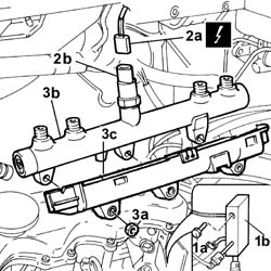
See in Op. 1048B22 See in Op. 1048B14 See in Op. 1060F20 See in Op. 1060G28 See in Op. 1060F361. Undo the fixing bolt (1a) and move the fuel return manifold pipe (1b) aside.2. Disconnect the electrical connection (2a) for the fuel pressure sensor (2b).
Description
Connector
2a
Fuel pressure sensor
K083
3. Undo the fixing nuts (3a) and move the brackets on the fastenings aside and remove the single fuel manifold pipe (3b) wih the protective casing (3c).
- Place the single fuel manifold pipe and protection in position.- Position the brackets on the fastenings.- Tighten the fixing nuts.- Connect the electrical connection for the fuel pressure sensor.
Description
Connector
.
Fuel pressure sensor
K083
- Position the fuel return manifold pipe and tighten the fixing bolt. See in Op. 1060F36 See in Op. 1060G28 See in Op. 1060F20 See in Op. 1048B14 See in Op. 1048B22
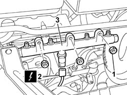
See in Op. 1060F20 See in Op. 1060F361. Undo the nuts fixing the fuel manifold to the cylinder head.2. Disconnect the electrical connection for the fuel pressure sensor.