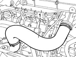
Position the vehicle on the lift.Vedere in Op. 1088B10 Op.5505A13CENTRALINA DI DERIVAZIONE SUPPLEMENTARE NEL VANO MOTORE - S.R.Op.7055B54PROTEZIONE/RIPARO SOTTOMOTORE - S.R. 1. Remove the air delivery hose to the air-air heat exchanger (intercooler).
Engines: 2.3 JTD 16V
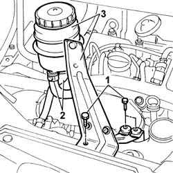
1. Undo the bolts securing the power steering fluid reservoir bracket. 2. Disconnect the fluid pipes from the reservoir. 3. Remove the power assisted steering fluid reservoir complete with bracket.
Engines: 2.3 JTD 16V
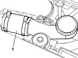
1. Remove the second section of the air delivery hose to the air-air heat exchanger (intercooler).
Engines: 2.3 JTD 16V
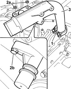
1. Loosen the bolt fixing the collar joining the rigid section of the intake pipe to the turbocharger. 2. Undo the nut (2a) fixing the pipe to the bracket on the cylinder head and the bolt (2b) fixing the connector for the engine oil vapour pipe. 3. Remove the rigid section of the air pipe from the turbocharger.
Engines: 2.3 JTD 16V
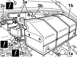
1. Undo the fixing bolts (1a) and remove the protective cover for the heater plugs control unit. 2. Disconnect the electrical connections for the heater plugs control unit (2a) and (2b) and the control unit positive electrical connection (2c).
[symbol: 771.jpg]
Description
Connector
2a
Heater plugs control unit
M015A
[symbol: 771_1.jpg]
Description
Connector
2b
Heater plugs control unit
M015B
[symbol: 771_2.jpg]
Description
Connector
2c
Heater plugs control unit
M015C
3. Undo the fixing nuts (3a) and remove the mounting bracket (3b) complete with heater plugs control unit.
Engines: 2.3 JTD 16V
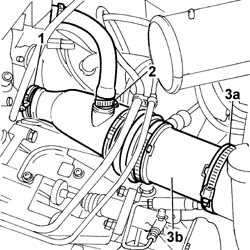
1. Disconnect the band fastening the air supply hose to the turbocharger. 2. Disconnect the vapour recovery pipe from the air supply hose to the turbocharger. 3. Disconnect the band from the air filter casing (3a) and remove the air supply hose to the turbocharger (3b).
Engines: 2.3 JTD 16V
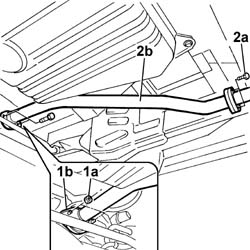
Raise the vehicle. 1. Undo the fixing nuts (1a) and separate the rigid middle section of the exhaust pipe from the turbocharger hose flange (1b). 2. Undo the bolts fixing the rear flange (2a) and remove the rigid middle section (2b) of the exhaust pipe.
Engines: 2.3 JTD 16V
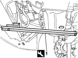
1. Position the tool for supporting the power unit fastened to the crossmember for the suspension and to the lower crossmember under the engine oil sump.
[symbol: 770.jpg]
Description
Code
Function
1
Crossmember
1.870.735.000
Lower engine mounting beam
Engines: 2.3 JTD 16V
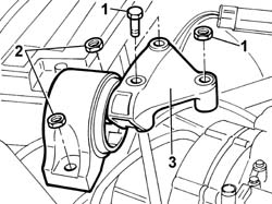
Lower the lift. 1. Undo the bolts and the nut fixing the flexible mounting to the rigid power unit support on the engine. 2. Undo the nuts fixing the flexible mounting to the bodyshell. 3. Remove the flexible mounting from the engine compartment.
Engines: 2.3 JTD 16V
1. Disconnect the connector for the turbocharger sump oil return pipe.Lower the vehicle. 2. Undo the connector and disconnect the turbocharger rigid oil supply pipe. 3. Undo the fixing nuts (3a) and remove the exhaust manifold (3b) complete with turbocharger from the lower part of the vehicle through the housing between the suspension crossmember and the bodyshell.
Fit the turbocharger assembly in the special housing and tighten the fixing nuts.Tighten the nuts fixing the turbocharger to the cylinder head to torque.
[symbol: 774.jpg]
Value - daNm
Fastening
Component
Ø
.
2.2
Nut
EXHAUST MANIFOLD/S
M8
Connect the rigid oil supply pipe to the turbocharger to the crankcase and tighten the connector.Lower the vehicle.Connect the connector for the turbocharger sump oil return pipe.Fit the flexible mounting in the housing in the engine compartment.Tighten the nuts securing the flexible mounting to the bodyshell.
[symbol: 774_1.jpg]
Value - daNm
Fastening
Component
Ø
.
(body block) 5
Nuts
FRONT FLEXIBLE MOUNTING BLOCKS, POWER UNIT
M10
Tighten the nut and the two bolts fixing the flexible mounting to the timing side rigid power unit support to torque.
[symbol: 774_2.jpg]
Value - daNm
Fastening
Component
Ø
.
(Rigid mount on engine) 5
Bolt
FRONT FLEXIBLE MOUNTING BLOCKS, POWER UNIT
M10
[symbol: 774_3.jpg]
Value - daNm
Fastening
Component
Ø
.
(Rigid mount on engine) 8
Nut
FRONT FLEXIBLE MOUNTING BLOCKS, POWER UNIT
M12
Remove the tool fitted previously for supporting the power unit from underneath the engine oil sump.
[symbol: 770_1.jpg]
Description
Code
Function
.
Crossmember
1.870.735.000
Lower engine mounting beam
Fit the exhaust pipe attachment to the engine.Tighten the bolts fixing the flange to the rear exhaust silencer.
[symbol: 774_4.jpg]
Value - daNm
Fastening
Component
Ø
.
2.6
Bolt
REAR SILENCER EXHAUST
M8
Tighten the nuts fixing the exhaust pipe to the turbocharger to torque.
[symbol: 774_5.jpg]
Value - daNm
Fastening
Component
Ø
.
2.6
Nuts
EXHAUST PIPE TO ENGINE
M8
Fit the air supply to the turbocharger and secure it to the air filter casing and to the turbine.Also connect the engine oil vapour recovery pipe to the air supply hose.Fit the mounting bracket complete with heater plugs control unit.Tighten the nuts fixing the control unit to the bodyshell.Connect the electrical connections for the heater plugs control unit.
[symbol: 771_3.jpg]
Description
Connector
.
Heater plugs control unit
M015A
[symbol: 771_4.jpg]
Description
Connector
.
Heater plugs control unit
M015B
[symbol: 771_5.jpg]
Description
Connector
.
Heater plugs control unit
M015C
Fit the protective cover for the heater plugs control unit and tighten the bolts fixing it to the mounting bracket underneath.Fit the rigid section of the air pipe from the turbocharger and tighten the bolt fixing the collar.Tighten the bolts fixing it to the cylinder head.Tighten the bolt fixing the engine oil vapour pipe.Fit the air hose from the intercooler to the intake manifold.Fit the second section of the air delivery hose to the air-air heat exchanger (intercooler).Fit the power steering fluid reservoir complete with bracket.Connect the oil hoses to the reservoir and tighten the power steering fluid reservoir bracket bolts to the beam.Op.5505A13CENTRALINA DI DERIVAZIONE SUPPLEMENTARE NEL VANO MOTORE - S.R.Vedere in Op. 1088B10 Op.7055B54PROTEZIONE/RIPARO SOTTOMOTORE - S.R.Remove the vehicle from the lift.
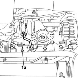
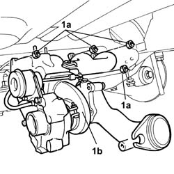
Vedere in Op. 1080C10 Vedere in Op. 1048A21 Vedere in Op. 1080C17 Vedere in Op. 1080C16 Op.1088D67TUBAZIONE LIQUIDO DI RAFFREDDAMENTO TRA SERBATOIO LIQUIDO RAFFREDDAMENTO E TERMOSTATO - S.R.Op.1080C50TUBAZIONE MANDATA GAS DI SCARICO A VALVOLA E.G.R. - S.R.Vedere in Op. 1080C80 Op.1080C54TUBAZIONE MANDATA GAS DI SCARICO DA VALVOLA E.G.R. A COLLETTORE ASPIRAZIONE - S.R.Op.1048A41MANICOTTO DA DEBIMETRO A TURBOCOMPRESSORE - S.R.Vedere in Op. 1084B40 Vedere in Op. 1048B10 Op.1076B14TUBAZIONE DI SCARICO CON CATALIZZATORE - S.R. 1. Undo the fixing bolts (1a) and move the oil return pipe (1b) aside.
Engines: 2.8 JTD 8V
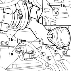
1. Undo the bolts (1a) fixing the turbocharger mounting brackets (1b).
Engines: 2.8 JTD 8V
1. Undo the nut (1a) fixing the exhaust manifold to the cylinder head and remove the turbocharger complete with exhaust manifold (1b).
Fit a new exhaust manifold gasket.Place the exhaust manifold assembly and turbine in position and tighten the nuts fixing the exhaust manifold to the cylinder head checking the torque.
[symbol: 774_6.jpg]
Value - daNm
Fastening
Component
Ø
.
(cylinder head side) 2.5
Nut
EXHAUST MANIFOLD/S
M8 X 1.25
Tighten the bolts fixing the turbo to the mounting brackets.Connect the oil return pipe and tighten the fixing bolts.Op.1076B14TUBAZIONE DI SCARICO CON CATALIZZATORE - S.R.Vedere in Op. 1048B10 Vedere in Op. 1084B40 Op.1048A41MANICOTTO DA DEBIMETRO A TURBOCOMPRESSORE - S.R.Op.1080C54TUBAZIONE MANDATA GAS DI SCARICO DA VALVOLA E.G.R. A COLLETTORE ASPIRAZIONE - S.R.Vedere in Op. 1080C80 Op.1080C50TUBAZIONE MANDATA GAS DI SCARICO A VALVOLA E.G.R. - S.R.Op.1088D67TUBAZIONE LIQUIDO DI RAFFREDDAMENTO TRA SERBATOIO LIQUIDO RAFFREDDAMENTO E TERMOSTATO - S.R.Vedere in Op. 1080C16 Vedere in Op. 1080C17 Vedere in Op. 1048A21 Vedere in Op. 1080C10 Op.0010T11OLIO MOTORE - VERIFICA LIVELLO ED EVENTUALE RIPRISTINO
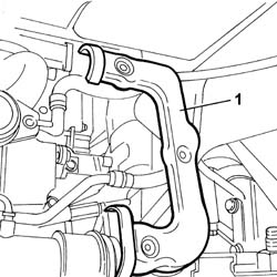
Position the vehicle on the lift.Op.7055B54PROTEZIONE/RIPARO SOTTOMOTORE - S.R.Vedere in Op. 1048A21 Vedere in Op. 1048A50 Op.1048B16TUBO/I E/O GOMITO TRA TURBOCOMPRESSORE E CORPO FARFALLE - S.R.Op.1048B12TUBO RIGIDO DI MANDATA ARIA TRA TURBOCOMPRESSORE E COLLETTORE DI ASPIRAZIONE - S.R.Vedere in Op. 1076B50 1. Remve the press-fitted EGR pipe heat shield.
Engines: 2.0 JTD 8V
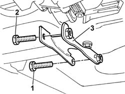
1. Undo the bolt securing the lower reaction rod to the suspension crossmember. 2. Undo the bolt securing the lower reaction rod to the mounting bracket on the gearbox.Move the power unit slightly forward to make enough room to remove the reaction link. 3. Remove the lower reaction link.
Engines: 2.0 JTD 8V
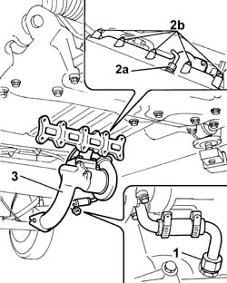
Move the power unit forward. 1. Disconnect the band for the turbocharger sump oil return pipe. 2. Undo the connector and disconnect the turbocharger rigid oil supply pipe. 3. Undo the fixing bolts (3a) and disconnect the EGR exhaust gas supply pipe from the turbocharger (3b); undo the bolt (3c) and disconnect the bracket (3d). 4. Undo the nuts securing the exhaust manifold to the cylinder head.Keep the spacers on the studs. 5. Undo the bolt securing the turbocharger to the mounting bracket. 6. Remove the exhaust manifold complete with turbocharger from the lower part of the vehicle from the compartment between the suspension beam and body.
Fit the exhaust manifold complete with turbocharger from the lower part of the vehicle from the compartment between the suspension beam and body.Tighten the bolt securing the turbocharger to the mounting bracket.Tighten the nuts securing the exhaust manifold to the cylinder head.
[symbol: 774_7.jpg]
Value - daNm
Fastening
Component
Ø
.
2,0
Nut
EXHAUST MANIFOLD/S
-
Connect the EGR exhaust gas delivery pipe from the turbocharger and tighten the retaining bolts.Connect the rigid oil supply pipe to the turbocharger and tighten the connector.Connect the band for the turbocharger sump oil return pipe.Fit the lower reaction rod in the housing and tighten the bolt fixing the suspension crossmember to torque.Tighten the nut fixing the reaction rod to the gearbox to torque.Fit the press-fitted EGR pipe heat shield.Vedere in Op. 1076B50 Op.1048B12TUBO RIGIDO DI MANDATA ARIA TRA TURBOCOMPRESSORE E COLLETTORE DI ASPIRAZIONE - S.R.Op.1048B16TUBO/I E/O GOMITO TRA TURBOCOMPRESSORE E CORPO FARFALLE - S.R.Vedere in Op. 1048A50 Vedere in Op. 1048A21 Op.7055B54PROTEZIONE/RIPARO SOTTOMOTORE - S.R.Remove the vehicle from the lift.