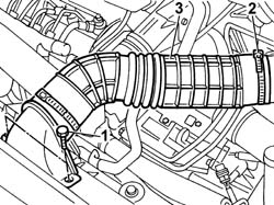
- Disconnect the negative battery terminal.- Position the vehicle on the lift.1. Undo the bolts fixing the cold air intake to the crossmember.2. Open the band securing the hose to the air filter.3. Remove the cold air intake and hose.
Engines: 2.8 JTD 8V Equipment / version codes: POWER Setup [TGV]
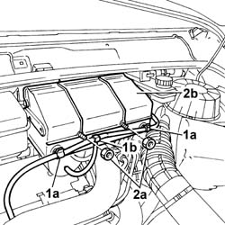
1. Open the retaining clips (1a) and move pipe (1b) out of the way.2. Undo the fixing nuts (2a) and remove the protective cover (2b).
Engines: 2.8 JTD 8V Equipment / version codes: POWER Setup [TGV]
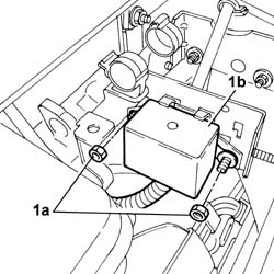
1. Undo the fixing nuts (1a) and move the control unit (1b) away from the work area.
Engines: 2.8 JTD 8V Equipment / version codes: POWER Setup [TGV]
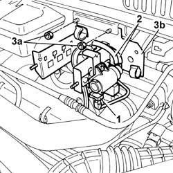
1. Disonnect the electrical connection for the waste gate valve.2. Disconnect the vacuum pipes.3. Undo the fixing nuts (3a) and remove the bracket (3b).
Engines: 2.8 JTD 8V Equipment / version codes: POWER Setup [TGV]
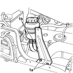
1. Undo the fixing bolts (1a) and move the fluid reservoir (1b) and mounting bracket outside of the work area.
Engines: 2.8 JTD 8V Equipment / version codes: POWER Setup [TGV]
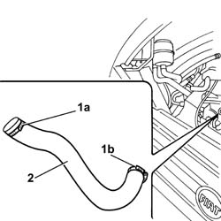
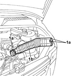
1. Undo the fixing bands (1a) and (1b).2. Remove the turbocharger intercooler air hose.
Engines: 2.8 JTD 8V Equipment / version codes: POWER Setup [TGV]
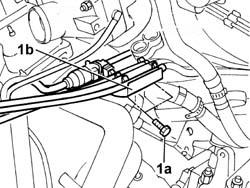
1. Undo the fixing bolts (1a) and move the fuel pipe mounting bracket (1b) aside.
Engines: 2.8 JTD 8V Equipment / version codes: POWER Setup [TGV]
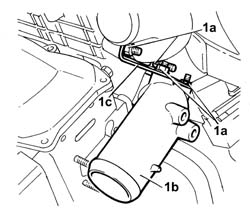
1. Undo the fixing nuts (1a) and remove the hose (1b) and the mounting bracket (1c).
Engines: 2.8 JTD 8V Equipment / version codes: POWER Setup [TGV]
1. Open the fastening bands (1a) and remove the air hose (1b).
Engines: 2.8 JTD 8V Equipment / version codes: POWER Setup [TGV]
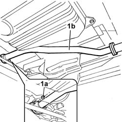
1. Undo the fixing nuts (1a) and move the front section (1b) of the exhaust pipe aside.
Engines: 2.8 JTD 8V Equipment / version codes: POWER Setup [TGV]
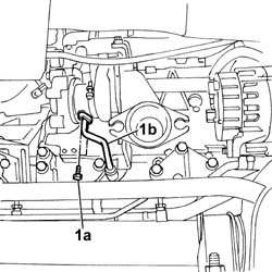
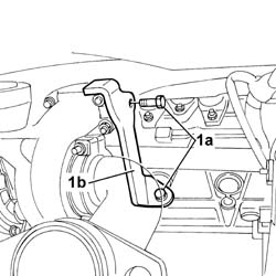
1. Undo the fixing bolts (1a) and disconnect the turbocharger oil outlet pipe (1b).
Engines: 2.8 JTD 8V Equipment / version codes: POWER Setup [TGV]
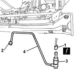
- Undo the bolt fixing the oil pipe to the turbocharger mounting bracket.1. Disconnect the electrical connection for the engine oil pressure sensor.
[symbol: elettrico 01.jpg]
Description
Connector
1
Engine oil pressure sensor
K028
2. Undo the connector for the oil pipe.3. Undo the sensor and remove it.4. Remove the oil pipe.
Engines: 2.8 JTD 8V Equipment / version codes: POWER Setup [TGV]
1. Undo the fixing bolts (1a) and remove the turbochrger mounting bracket (1b).
Engines: 2.8 JTD 8V Equipment / version codes: POWER Setup [TGV]
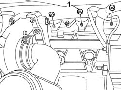
1. Undo the bolts fixing the exhaust manifold.
Engines: 2.8 JTD 8V Equipment / version codes: POWER Setup [TGV]
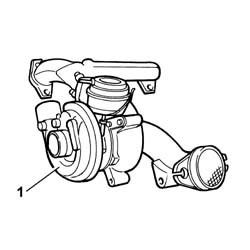
1. Remove the turbocharger and exhaust manifold assembly.
Engines: 2.8 JTD 8V Equipment / version codes: POWER Setup [TGV]
- Fit the exhaust manifold and turbocharger assembly in place and tighten the nuts to torque.
[symbol: coppie 02.jpg]
Value - daNm
Fastening
Component
Ø
-
2,5
Nut
-
M8x1.25
- Fit the mounting bracket for the turbocharger and tighten the fixing bolts.- Connect the oil return pipe to the turbine and tighten the fixing bolts.- Fit the rigid oil pipe and tighten the connector to the turbine.- Fit the engine oil pressure sensor in place and connect the electrical connection.
[symbol: elettrico 02.jpg]
Description
Connector
-
Engine oil pressure sensor
K028
- Fit the front section of the exhaust pipe in place and tighten the fixing nuts.- Fit the rigid section of the air pipe to the turbine and the mounting bracket in place and tighten the fixing nuts. - Fit the air hose and restore the retaining bands.- Tighten the fuel pipe mounting bracket fixing bolts.- Fit the air hose from the turbocharger to the air/air heat exchanger.- Position the fluid reservoir and mounting bracket and tighten the fixing bolts.- Place the waste gate valve mounting bracket in position and tighten the fixing nuts.- Connect the waste gate valve vacuum pipes.- Place the control unit in position and tighten the fixing nuts.- Fit the protective cover and tighten the fixing nuts and fit the pipe in place on the cover.- Fit the cold air intake and hose and tighten the fixing bolts and renew the hose fastening band.- Connect the negative battery terminal.- Remove the vehicle from the lift.