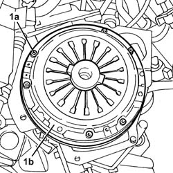
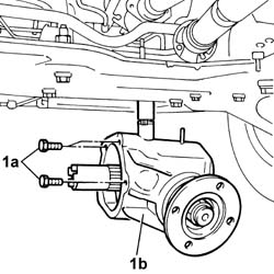
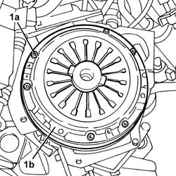
1. Undo the bolts (1a) and remove the pressure plate and the clutch disc (1b).
Engines: 2.0 16V, 2.8 JTD 8V
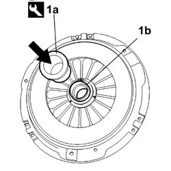
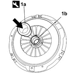
1. Remove the thrust bearing (1b) from the clutch using the tool (1a).
[symbol: attrezzi 07.jpg]
Description
Code
Function
1a
Extractor
1.870.840.000
Thrust bearing removal
Engines: 2.0 16V, 2.8 JTD 8V
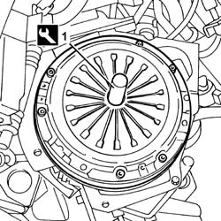
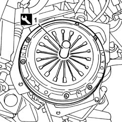
1. Fit the driven disc and the pressure plate and align them using the clutch centering tool.
[symbol: attrezzi 08.jpg]
Description
Code
Function
1
Clutch locating tool
1.870.402.000
Driven plate locating
Engines: 2.0 16V, 2.8 JTD 8V
- Tighten the bolts fixing the clutch to the flywheel to torque.
[symbol: coppie 01.jpg]
Value - daNm
Fastening
Component
Ø
-
3,2
Bolt
CLUTCH ASSEMBLY
M8
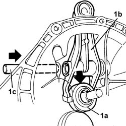
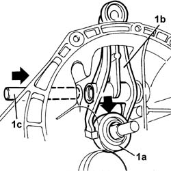
1. Position the thrust bearing (1a) on the main gearbox shaft hose and fit it on the clutch release lever (1b), then fit the release lever fixing shaft (1c).
Engines: 2.0 16V, 2.8 JTD 8V
- Fit the gearbox-differential unit and tighten the nuts and bolts to torque.
[symbol: coppie 02.jpg]
Value - daNm
Fastening
Component
Ø
-
7
Bolt
MANUAL GEARBOX/DIFFERENTIAL
M12
[symbol: coppie 03.jpg]
Value - daNm
Fastening
Component
Ø
-
6
Nut
MANUAL GEARBOX/DIFFERENTIAL
M10
- Fit the rear bracket joining the gearbox to the engine.- Tighten the fixing bolts to torque.- Fit the front bracket joining the gearbox to the front of the engine.- Tighten the fixing bolts to torque.- Tighten the nut fixing the lower shaft to the power assisted steering box pinion to torque.
[symbol: coppie 04.jpg]
Value - daNm
Fastening
Component
Ø
-
2,5
Bolt
FIXED ELEMENTS STEERING SHAFT STEERING
M8
- Place the heat shield in position.- Tighten the bolts securing the power assisted steering box to the crossmember to torque.
[symbol: coppie 05.jpg]
Value - daNm
Fastening
Component
Ø
-
11
Bolts
COMPLETE POWER ASSISTED STEERING BOX
M12
- Fit the lower reaction rod in the housing and tighten the bolt fixing the suspension crossmember to torque.- Tighten the nut fixing the reaction rod to the gearbox to torque.- Fit the gearbox side rigid engine support.- Tighten the bolts fixing the gearbox side flexible mounting to the rigid support.
[symbol: coppie 06.jpg]
Value - daNm
Fastening
Component
Ø
-
5
Bolt
GEARBOX SIDE RUBBER MOUNT
M10
- Tighten the bolts and the nut fixing the rigid support to the gearbox to torque.
[symbol: coppie 07.jpg]
Value - daNm
Fastening
Component
Ø
-
9
Nut
GEARBOX SIDE RUBBER MOUNT
M14
[symbol: coppie 08.jpg]
Value - daNm
Fastening
Component
Ø
-
9
Bolt
GEARBOX SIDE RUBBER MOUNT
M14
- Remove the tool complete with brackets positioned previously for supporting the gearbox.
[symbol: attrezzi 09.jpg]
Description
Code
Function
-
Hydraulic lift
1.870.835.001
Removing the gearbox
[symbol: attrezzi 10.jpg]
Description
Code
Function
-
Mounting brackets
1.870.847.000
Removing the gearbox
- Fit the idler connecting rod on the gear selector and enagement assembly, tighten the nut and fit the plug.- Fit the operating cylinder mounting bracket on the bellhousing.- Tighten the retaining nuts.- Connect the electrical connection for the engine rpm sensor.
[symbol: elettrico 09.jpg]
Description
Connector
-
Rpm sensor
K046
- Remove the tool for supporting the power unit, fastened to the suspension crossmember and to the lower crossmember, from under the engine oil sump.
[symbol: attrezzi 11.jpg]
Description
Code
Function
-
Crossmember
1.870.735.000
Crossmember
- Place the rear drive idler casing in position and tighten the fixing bolts.- Tighten the speedometer in place.- Fit the hose connecting the turbocharger and the exhaust pipe in place and tighten the fixing bolts.- Tighten the bolts fixing the hose joining the turbocharger and the exhaust pipe to the mounting bracket.1. Undo the plug and top up the fluid in the rear drive idler casing.
Engines: 2.0 16V, 2.8 JTD 8V
- Connect the electrical connection and the vacuum pipes to the rear drive ilder casing.- Fit the front propeller shaft in position and tighten the bolts fixing the universal joint to the rear drive idler unit flange.- Fit the front propeller shaft safety bracket in place and tighten the fixing bolts.- Tighten the greaser for the universal joint securing the front propeller shaft to the rear drive idler unit.- Fit the starter motor and tighten the retaining bolts to torque.
[symbol: coppie 09.jpg]
Value - daNm
Fastening
Component
Ø
-
2
Bolt
STARTER MOTOR
M8
- Connect the starter motor electrical wiring
[symbol: elettrico 10.jpg]
Description
Connector
-
Starter motor
A020A
[symbol: elettrico 11.jpg]
Description
Connector
-
Starter motor
A020B
- Fit the rigid middle section of the exhaust pipe and tighten the bolts securing it to the rear section to torque.
[symbol: coppie 10.jpg]
Value - daNm
Fastening
Component
Ø
-
2,6
Bolts
REAR SILENCER EXHAUST
M8
- Tighten the nuts securing the front section of the exhaust pipe to the turbocharger to torque.
[symbol: coppie 11.jpg]
Value - daNm
Fastening
Component
Ø
-
2,6
Nut
REAR SILENCER EXHAUST
M8
- Fit the inner driveshaft in the housing on the differential for the right driveshaft.- Tighten the bolts fixing the steering knuckle to the shock absorber to torque.
[symbol: coppie 12.jpg]
Value - daNm
Fastening
Component
Ø
-
19
Bolts
FRONT HUB STRUT
M16
- Tighten the nut fixing the ball joint to the steering rod to torque.
[symbol: coppie 13.jpg]
Value - daNm
Fastening
Component
Ø
-
6,9
Bolt
ADJUSTABLE LINK BALL JOINTS
M16
- Fit the brake caliper - bracket assembly and tighten the bolts fixing the bracket to the left disc to torque.
[symbol: coppie 14.jpg]
Value - daNm
Fastening
Component
Ø
-
21
Bolt
FRONT DISC BRAKE CALIPER BRACKET
M16
- Fit the right driveshaft - intermediate driveshaft assembly.- Tighten the nuts securing the intermediate driveshaft to the support to torque.
[symbol: coppie 15.jpg]
Value - daNm
Fastening
Component
Ø
-
-
Nut
INTERMEDIATE DRIVE SHAFT
-
- Tighten the bolts fixing the steering knuckle to the shock absorber to torque.
[symbol: coppie 16.jpg]
Value - daNm
Fastening
Component
Ø
-
19
Bolts
FRONT HUB STRUT
M16
- Tighten the nut fixing the ball joint to the steering rod to torque.
[symbol: coppie 17.jpg]
Value - daNm
Fastening
Component
Ø
-
6,9
Nut
ADJUSTABLE LINK BALL JOINTS
M16
- Fit the brake caliper - bracket assembly and tighten the bolts fixing the bracket to the disc to torque.
[symbol: coppie 18.jpg]
Value - daNm
Fastening
Component
Ø
-
21
Bolt
FRONT BRAKE CALIPER BRACKET
M16
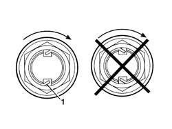
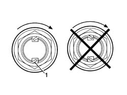
1. Use a hammer and chisel to stake the wheel hub drive shaft retaining nut as shown in the figure.- The figure below refers to the 1500 kg version.
[symbol: coppie 19.jpg]
Value - daNm
Fastening
Component
Ø
-
-
Nut
FRONT HUBS COMPLETE WITH BEARING
M28
- The figure below refers to the 1800 kg version.
[symbol: coppie 20.jpg]
Value - daNm
Fastening
Component
Ø
-
-
Nut
FRONT HUBS COMPLETE WITH BEARING
M33
Engines: 2.0 16V, 2.8 JTD 8V
Op.4450B12RUOTE (DUE) ANTERIORI - S.R.Op.4450B04RUOTA ANTERIORE DESTRA - S.R.- Lower the lift.- Connect the electrical connection for the reversing light switch.
[symbol: elettrico 12.jpg]
Description
Connector
-
Reversing light switch
I020
- Connect the earth lead to the gearbox and tighten the fixing nut.- Lock the ends of the gear selector and engagement flexible cables.- Secure the cables to the mounting bracket.- Fit the clutch actuator cylinder mounting bracket in its seat on the gearbox.- Fit the clutch release operating cylinder in the housing on the gearbox and tighten the fixing bolts.- Fit the air cleaner case in position and tighten the fixing bolts.- Connect the air sleeve to the turbine and renew the retaining clips.- Connect the oil vapour recovery pipe and renew the retaining band.- Fit the fuse box in position and tighten the fixing bolts.- Place the control unit in its housing.- Fit the protective cover for the fuse box and tighten the fixing bolt.- Fit the cold intake and intake hose assembly in the engine compartment.- Connect the intake hose to the air filter casing.- Tighten the bolts fixing the cold air intake to the upper crossmember.- Place the solenoid valve mounting bracket in position and tighten the fixing nuts.- Connect the electrical connection for the windscreen wiper motor.
[symbol: elettrico 13.jpg]
Description
Connector
-
Windscreen wiper motor
N015
- Connect the electrical connection for the thermal starter solenoid valve.
[symbol: elettrico 14.jpg]
Description
Connector
-
Thermal starter solenoid valve
L085
- Connect the electrical connection for the thermal starter resistance.
[symbol: elettrico 15.jpg]
Description
Connector
-
Thermal starter resistance
O004
- Connect the electrical connection for the air flow meter.
[symbol: elettrico 16.jpg]
Description
Connector
-
Air flow meter
K041
- Connect the electrical connection.- Fit the protective cover in place and tighten the nuts. - Fit the vacuum pipe on the cover fastening clips.- Connect the negative battery terminal.- Remove the vehicle from the lift.
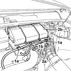
- Position the vehicle on the lift.- Disconnect the negative battery terminal.1. Open the fastening clips (1a) and release the vacuum pipe (1b).2. Undo the fixing nuts (2a) and remove the protective cover (2b).
Engines: 2.0 16V, 2.8 JTD 8V
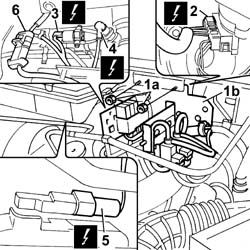
1. Undo the fixing nuts (1a) and remove the solenoid valve mounting bracket (1b) from its housing.2. Disconnect the electrical connection for the windscreen wiper motor.
[symbol: elettrico 01.jpg]
Description
Connector
2
Windscreen wiper motor
N015
3. disconnect the electrical connection for the thermal starter solenoid valve.
[symbol: elettrico 02.jpg]
Description
Connector
3
Thermal starter solenoid valve
L085
4. Disconnect the electrical connection for the thermal starter resistance.
[symbol: elettrico 03.jpg]
Description
Connector
4
Thermal starter resistance
O004
5. Disconnect the electrical connection for the air flow meter.
[symbol: elettrico 04.jpg]
Description
Connector
5
Air flow meter
K041
6. Disconnect the electrical connection.- Free up the working area.
Engines: 2.0 16V, 2.8 JTD 8V
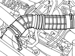
1. Undo the bolts fixing the cold air intake to the upper crossmember.2. Disconnect the intake hose from the air filter casing.3. Remove the cold intake and intake hose assembly from the engine compartment.
Engines: 2.0 16V, 2.8 JTD 8V
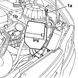
1. Undo the fixing bolts (1a) and remove the fuse box protective cover (1b).
Engines: 2.0 16V, 2.8 JTD 8V
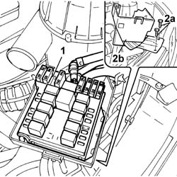
1. Move the fuse box aside.2. Undo the fixing nuts (2a) and remove the pipe (2b) complete with mounting bracket.
Engines: 2.0 16V, 2.8 JTD 8V
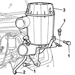
- Open the clip securing the pipe from turbine to air cleaner casing.1. Undo the retaining bolts.2. Open the band and disconnect the pipe from the vacuum unit.3. Remove the air cleaner casing with its bracket.
Engines: 2.0 16V, 2.8 JTD 8V
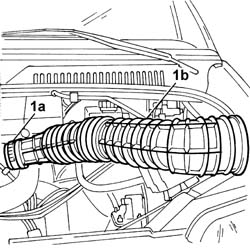
1. Open the retaining band (1a) and release the air hose (1b).
Engines: 2.0 16V, 2.8 JTD 8V
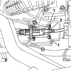
1. Undo the retaining bolts.2. Remove the clutch release cylinder.
Engines: 2.0 16V, 2.8 JTD 8V
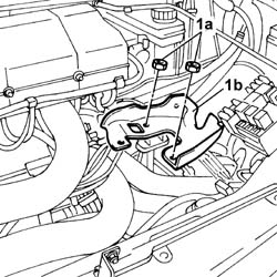
1. Undo the fixing nuts (1a) and remove the clutch release cylinder mounting bracket (1b).
Engines: 2.0 16V, 2.8 JTD 8V
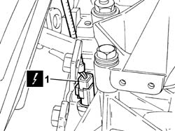
1. Disconnect the electrical connection for the reversing light switch.
[symbol: elettrico 05.jpg]
Description
Connector
1
Reversing light switch
I020
Engines: 2.0 16V, 2.8 JTD 8V
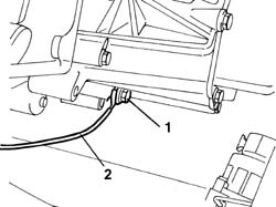
1. Undo the retaining bolt.2. Disconnect the earth lead from the gearbox.
Engines: 2.0 16V, 2.8 JTD 8V
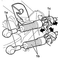
1. Release the two ends (1a), move the two gear selector and engagement flexible cables (1b) out of the slot in the bracket (1c) and place them outside of the work area.
Engines: 2.0 16V, 2.8 JTD 8V
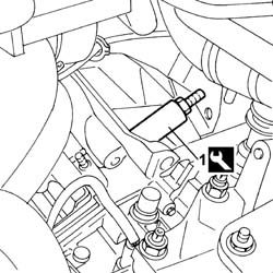
1. Fit the tool into the groove on the fork lever pin and remove the pin.
[symbol: attrezzi 01.jpg]
Description
Code
Function
1
Extractor
1.870.873.000
Remove the fork lever pin
- Remove the tool.
Engines: 2.0 16V, 2.8 JTD 8V
Op.4450B04RUOTA ANTERIORE DESTRA - S.R.Op.4450B12RUOTE (DUE) ANTERIORI - S.R.- Position a suitable container for collecting the gearbox fluid.1. Unscrew the oil drain plug.
Engines: 2.0 16V, 2.8 JTD 8V
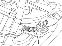
- Position a hydraulic column lift under the track control arm to work safely.1. Undo the nut fixing the track rod end to the steering knuckle.2. Extract the track rod end from the housing in the steering knuckle using the tool.
[symbol: attrezzi 02.jpg]
Description
Code
Function
-
Head extractor
1.871.000.700
Ball joint removal
Engines: 2.0 16V, 2.8 JTD 8V
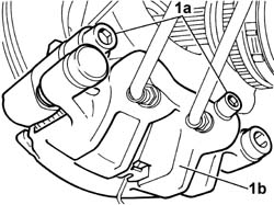
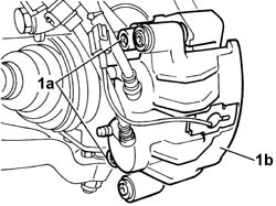
1. Undo the fixing bolts (1a) and remove the brake caliper-bracket assembly (1b) from the brake disc without disconnect the fluid pipes.
Engines: 2.0 16V, 2.8 JTD 8V
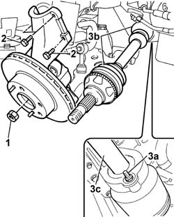
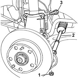
1. Remove the staking and undo the right hub nut.2. Undo the bolts fixing the steering knuckle to the shock absorber.3. Undo the nuts (3a) and remove the right driveshaft (3b) complete with intermediate shaft (3c).
Engines: 2.0 16V, 2.8 JTD 8V
1. Undo the fixing bolts (1a) and remove the left brake caliper-bracket assembly (1b) from the brake disc without disconnect the fluid pipes.
Engines: 2.0 16V, 2.8 JTD 8V
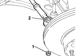
1. Undo the nut fixing the track rod end to the steering knuckle.2. Extract the track rod end from the housing in the steering knuckle using the tool.
[symbol: attrezzi 03.jpg]
Description
Code
Function
-
Head extractor
1.871.000.700
Ball joint removal
3. Undo the bolts fixing the steering knuckle to the shock absorber.
Engines: 2.0 16V, 2.8 JTD 8V
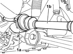
1. Release the inner driveshaft (1a) from the differential and move the right driveshaft (1b) away from the work area.
Engines: 2.0 16V, 2.8 JTD 8V
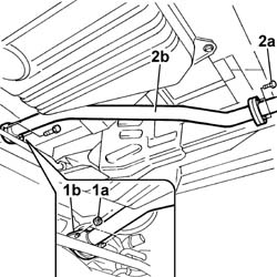
1. Undo the fixing nuts (1a) and separate the ridid middle section of the exhaust pipe from the turbocharger hose flange (1b).2. Undo the bolts fixing the rear flange (2a) and remove the rigid middle section (2b) of the exhaust pipe.
Engines: 2.0 16V, 2.8 JTD 8V
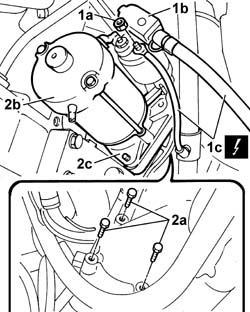
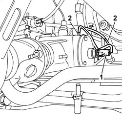
1. Undo the nut (1a), remove the protective cover (1b) and disconnect the starter motor supply leads (1c).2. Undo the retaining bolts (2a) and remove the starter motor (2b), complete with spacer (2c).
[symbol: elettrico 06.jpg]
Description
Connector
1c
Starter motor
A020A
[symbol: elettrico 07.jpg]
Description
Connector
1c
Starter motor
A020B
Engines: 2.0 16V, 2.8 JTD 8V
- Disconnect the electrical connection for the engine rpm sensor.
[symbol: elettrico 08.jpg]
Description
Connector
-
Rpm sensor
K046
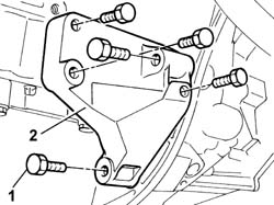
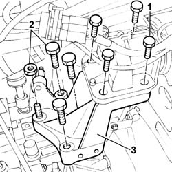
1. Undo the bolts fixing it to the gearbox and to the cylinder block/crankcase.2. Remove the front support joining the engine to the gearbox.
Engines: 2.0 16V, 2.8 JTD 8V
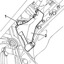
1. Undo the retaining bolts.2. Remove the rear bracket joining the gearbox to the engine.
Engines: 2.0 16V, 2.8 JTD 8V
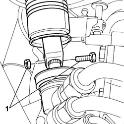
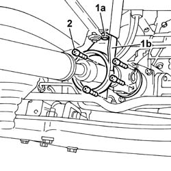
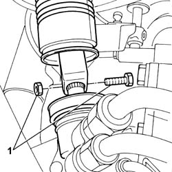
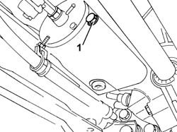
- Loosen the greaser for the universal joint securing the front propeller shaft to the rear drive idler unit.1. Undo the fixing bolts (1a) and move the safety bracket (1b) aside.2. Loosen the bolts fixing the front propeller shaft universal joint to the rear drive idler unit and move it aside.
Engines: 2.0 16V, 2.8 JTD 8V
1. Disconnect the electrical connection.2. Disconnect vacuum pipes.
Engines: 2.0 16V, 2.8 JTD 8V
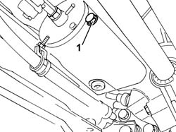
- Position a suitable container for collecting the oil from the rear drive idler casing.1. Undo the plug and drain the fluid from the rear drive idler casing.
Engines: 2.0 16V, 2.8 JTD 8V
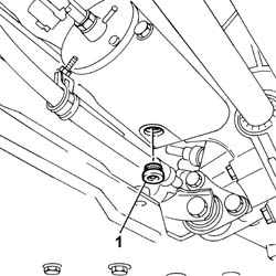
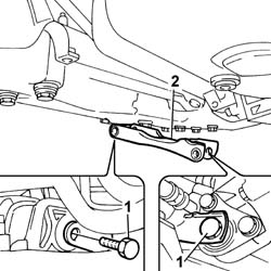
1. Undo the retaining bolts.2. Remove the lower reaction link.
Engines: 2.0 16V, 2.8 JTD 8V
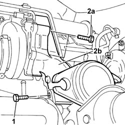
1. Undo the bolts fixing the hose joining the turbocharger and the exhaust pipe to the mounting bracket.2. Undo the fixing bolts (2a) and remove the hose joining the turbocharger and the exhaust pipe (2b).
Engines: 2.0 16V, 2.8 JTD 8V
- Undo the speedometer and move it aside.1. Undo the fixing bolts (1a) and remove the rear drive idler casing (1b).
Engines: 2.0 16V, 2.8 JTD 8V
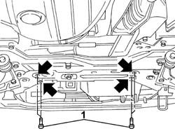
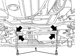
1. Place the tool for supporting the power unit, fastened to the suspension crossmember and to the lower crossmember, under the engine oil sump in a central position.2. In order to be able to position the crossmember correctly and safely, the corners of the actual crossmember at the two ends have to be smoothed making sure that they match correctly with the front crossmember and the suspension crossmember.
[symbol: attrezzi 04.jpg]
Description
Code
Function
1
Crossmember
1.870.735.000
Crossmember
Engines: 2.0 16V, 2.8 JTD 8V
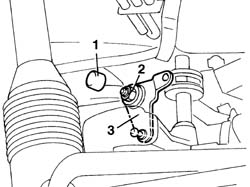
1. Remove the cover (1a), undo the nut (1b) and remove the selector unit idler connecting rod (1c).
Engines: 2.0 16V, 2.8 JTD 8V
1. Undo the bolts fixing the gearbox side flexible mounting to the rigid support.2. Undo the bolts and the nut fixing the rigid support to the gearbox.- Gently lower the engine until the stud on the rigid support comes out of the housing in the flexible mounting.3. Remove the gearbox side rigid power unit support.
Engines: 2.0 16V, 2.8 JTD 8V
- Move aside the steering box universal joint gaiter on the steering column.1. Undo the bolt securing the steering column to the steering box.
Engines: 2.0 16V, 2.8 JTD 8V
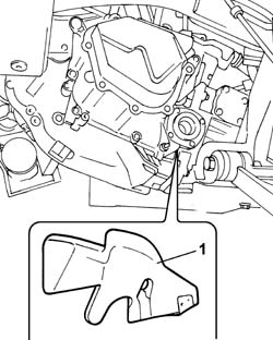
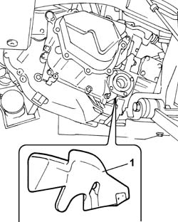
1. Remove the dust shield.
Engines: 2.0 16V, 2.8 JTD 8V
1. Undo the bolts securing the power assisted steering box to the crossmember.
Engines: 2.0 16V, 2.8 JTD 8V
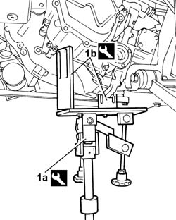
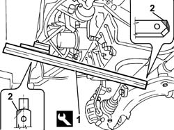
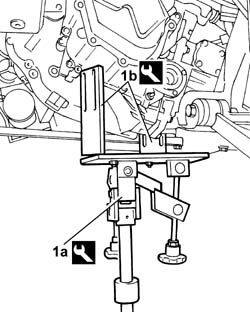
1. Position a suitable hydraulic lift (1a) with the appropriate mounting brackets (1b) and secure them to the gearbox.
[symbol: attrezzi 05.jpg]
Description
Code
Function
1a
Hydraulic lift
1.870.835.001
Removing the gearbox
[symbol: attrezzi 06.jpg]
Description
Code
Function
1b
Mounting bracket
1.870.847.000
Removing the gearbox
Engines: 2.0 16V, 2.8 JTD 8V
1. Undo the fixing bolts (1a) and remove the gearbox and differential unit (1b).
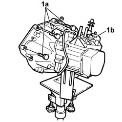
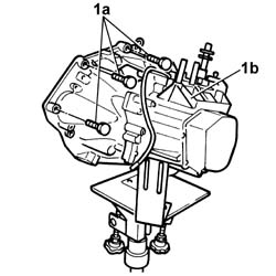
1. Undo the bolts (1a) and remove the pressure plate and the clutch disc (1b).
Engines: 2.0 16V, 2.8 JTD 8V
1. Remove the thrust bearing (1b) from the clutch using the tool (1a).
[symbol: attrezzi 07.jpg]
Description
Code
Function
1a
Extractor
1.870.840.000
Thrust bearing removal
Engines: 2.0 16V, 2.8 JTD 8V
1. Fit the driven disc and the pressure plate and align them using the clutch centering tool.
[symbol: attrezzi 08.jpg]
Description
Code
Function
1
Clutch locating tool
1.870.402.000
Driven plate locating
Engines: 2.0 16V, 2.8 JTD 8V
- Tighten the bolts fixing the clutch to the flywheel to torque.
[symbol: coppie 01.jpg]
Value - daNm
Fastening
Component
Ø
-
3,2
Bolt
CLUTCH ASSEMBLY
M8
1. Position the thrust bearing (1a) on the main gearbox shaft hose and fit it on the clutch release lever (1b), then fit the release lever fixing shaft (1c).
Engines: 2.0 16V, 2.8 JTD 8V
- Fit the gearbox-differential unit and tighten the nuts and bolts to torque.
[symbol: coppie 02.jpg]
Value - daNm
Fastening
Component
Ø
-
7
Bolt
MANUAL GEARBOX/DIFFERENTIAL
M12
[symbol: coppie 03.jpg]
Value - daNm
Fastening
Component
Ø
-
6
Nut
MANUAL GEARBOX/DIFFERENTIAL
M10
- Fit the rear bracket joining the gearbox to the engine.- Tighten the fixing bolts to torque.- Fit the front bracket joining the gearbox to the front of the engine.- Tighten the fixing bolts to torque.- Tighten the nut fixing the lower shaft to the power assisted steering box pinion to torque.
[symbol: coppie 04.jpg]
Value - daNm
Fastening
Component
Ø
-
2,5
Bolt
FIXED ELEMENTS STEERING SHAFT STEERING
M8
- Place the heat shield in position.- Tighten the bolts securing the power assisted steering box to the crossmember to torque.
[symbol: coppie 05.jpg]
Value - daNm
Fastening
Component
Ø
-
11
Bolts
COMPLETE POWER ASSISTED STEERING BOX
M12
- Fit the lower reaction rod in the housing and tighten the bolt fixing the suspension crossmember to torque.- Tighten the nut fixing the reaction rod to the gearbox to torque.- Fit the gearbox side rigid engine support.- Tighten the bolts fixing the gearbox side flexible mounting to the rigid support.
[symbol: coppie 06.jpg]
Value - daNm
Fastening
Component
Ø
-
5
Bolt
GEARBOX SIDE RUBBER MOUNT
M10
- Tighten the bolts and the nut fixing the rigid support to the gearbox to torque.
[symbol: coppie 07.jpg]
Value - daNm
Fastening
Component
Ø
-
9
Nut
GEARBOX SIDE RUBBER MOUNT
M14
[symbol: coppie 08.jpg]
Value - daNm
Fastening
Component
Ø
-
9
Bolt
GEARBOX SIDE RUBBER MOUNT
M14
- Remove the tool complete with brackets positioned previously for supporting the gearbox.
[symbol: attrezzi 09.jpg]
Description
Code
Function
-
Hydraulic lift
1.870.835.001
Removing the gearbox
[symbol: attrezzi 10.jpg]
Description
Code
Function
-
Mounting brackets
1.870.847.000
Removing the gearbox
- Fit the idler connecting rod on the gear selector and enagement assembly, tighten the nut and fit the plug.- Fit the operating cylinder mounting bracket on the bellhousing.- Tighten the retaining nuts.- Connect the electrical connection for the engine rpm sensor.
[symbol: elettrico 09.jpg]
Description
Connector
-
Rpm sensor
K046
- Remove the tool for supporting the power unit, fastened to the suspension crossmember and to the lower crossmember, from under the engine oil sump.
[symbol: attrezzi 11.jpg]
Description
Code
Function
-
Crossmember
1.870.735.000
Crossmember
- Place the rear drive idler casing in position and tighten the fixing bolts.- Tighten the speedometer in place.- Fit the hose connecting the turbocharger and the exhaust pipe in place and tighten the fixing bolts.- Tighten the bolts fixing the hose joining the turbocharger and the exhaust pipe to the mounting bracket.1. Undo the plug and top up the fluid in the rear drive idler casing.
Engines: 2.0 16V, 2.8 JTD 8V
- Connect the electrical connection and the vacuum pipes to the rear drive ilder casing.- Fit the front propeller shaft in position and tighten the bolts fixing the universal joint to the rear drive idler unit flange.- Fit the front propeller shaft safety bracket in place and tighten the fixing bolts.- Tighten the greaser for the universal joint securing the front propeller shaft to the rear drive idler unit.- Fit the starter motor and tighten the retaining bolts to torque.
[symbol: coppie 09.jpg]
Value - daNm
Fastening
Component
Ø
-
2
Bolt
STARTER MOTOR
M8
- Connect the starter motor electrical wiring
[symbol: elettrico 10.jpg]
Description
Connector
-
Starter motor
A020A
[symbol: elettrico 11.jpg]
Description
Connector
-
Starter motor
A020B
- Fit the rigid middle section of the exhaust pipe and tighten the bolts securing it to the rear section to torque.
[symbol: coppie 10.jpg]
Value - daNm
Fastening
Component
Ø
-
2,6
Bolts
REAR SILENCER EXHAUST
M8
- Tighten the nuts securing the front section of the exhaust pipe to the turbocharger to torque.
[symbol: coppie 11.jpg]
Value - daNm
Fastening
Component
Ø
-
2,6
Nut
REAR SILENCER EXHAUST
M8
- Fit the inner driveshaft in the housing on the differential for the right driveshaft.- Tighten the bolts fixing the steering knuckle to the shock absorber to torque.
[symbol: coppie 12.jpg]
Value - daNm
Fastening
Component
Ø
-
19
Bolts
FRONT HUB STRUT
M16
- Tighten the nut fixing the ball joint to the steering rod to torque.
[symbol: coppie 13.jpg]
Value - daNm
Fastening
Component
Ø
-
6,9
Bolt
ADJUSTABLE LINK BALL JOINTS
M16
- Fit the brake caliper - bracket assembly and tighten the bolts fixing the bracket to the left disc to torque.
[symbol: coppie 14.jpg]
Value - daNm
Fastening
Component
Ø
-
21
Bolt
FRONT DISC BRAKE CALIPER BRACKET
M16
- Fit the right driveshaft - intermediate driveshaft assembly.- Tighten the nuts securing the intermediate driveshaft to the support to torque.
[symbol: coppie 15.jpg]
Value - daNm
Fastening
Component
Ø
-
-
Nut
INTERMEDIATE DRIVE SHAFT
-
- Tighten the bolts fixing the steering knuckle to the shock absorber to torque.
[symbol: coppie 16.jpg]
Value - daNm
Fastening
Component
Ø
-
19
Bolts
FRONT HUB STRUT
M16
- Tighten the nut fixing the ball joint to the steering rod to torque.
[symbol: coppie 17.jpg]
Value - daNm
Fastening
Component
Ø
-
6,9
Nut
ADJUSTABLE LINK BALL JOINTS
M16
- Fit the brake caliper - bracket assembly and tighten the bolts fixing the bracket to the disc to torque.
[symbol: coppie 18.jpg]
Value - daNm
Fastening
Component
Ø
-
21
Bolt
FRONT BRAKE CALIPER BRACKET
M16
1. Use a hammer and chisel to stake the wheel hub drive shaft retaining nut as shown in the figure.- The figure below refers to the 1500 kg version.
[symbol: coppie 19.jpg]
Value - daNm
Fastening
Component
Ø
-
-
Nut
FRONT HUBS COMPLETE WITH BEARING
M28
- The figure below refers to the 1800 kg version.
[symbol: coppie 20.jpg]
Value - daNm
Fastening
Component
Ø
-
-
Nut
FRONT HUBS COMPLETE WITH BEARING
M33
Engines: 2.0 16V, 2.8 JTD 8V
Op.4450B12RUOTE (DUE) ANTERIORI - S.R.Op.4450B04RUOTA ANTERIORE DESTRA - S.R.- Lower the lift.- Connect the electrical connection for the reversing light switch.
[symbol: elettrico 12.jpg]
Description
Connector
-
Reversing light switch
I020
- Connect the earth lead to the gearbox and tighten the fixing nut.- Lock the ends of the gear selector and engagement flexible cables.- Secure the cables to the mounting bracket.- Fit the clutch actuator cylinder mounting bracket in its seat on the gearbox.- Fit the clutch release operating cylinder in the housing on the gearbox and tighten the fixing bolts.- Fit the air cleaner case in position and tighten the fixing bolts.- Connect the air sleeve to the turbine and renew the retaining clips.- Connect the oil vapour recovery pipe and renew the retaining band.- Fit the fuse box in position and tighten the fixing bolts.- Place the control unit in its housing.- Fit the protective cover for the fuse box and tighten the fixing bolt.- Fit the cold intake and intake hose assembly in the engine compartment.- Connect the intake hose to the air filter casing.- Tighten the bolts fixing the cold air intake to the upper crossmember.- Place the solenoid valve mounting bracket in position and tighten the fixing nuts.- Connect the electrical connection for the windscreen wiper motor.
[symbol: elettrico 13.jpg]
Description
Connector
-
Windscreen wiper motor
N015
- Connect the electrical connection for the thermal starter solenoid valve.
[symbol: elettrico 14.jpg]
Description
Connector
-
Thermal starter solenoid valve
L085
- Connect the electrical connection for the thermal starter resistance.
[symbol: elettrico 15.jpg]
Description
Connector
-
Thermal starter resistance
O004
- Connect the electrical connection for the air flow meter.
[symbol: elettrico 16.jpg]
Description
Connector
-
Air flow meter
K041
- Connect the electrical connection.- Fit the protective cover in place and tighten the nuts. - Fit the vacuum pipe on the cover fastening clips.- Connect the negative battery terminal.- Remove the vehicle from the lift.