Procedures
2110B20 MANUAL GEARBOX (5 SPEED) WITH DIFFERENTIAL - DISMANTLE AND REBUILD - WASH AND CHECK PARTS - REPLACE SYNCHRONISERS AND INTERNAL CONTROLS IF NECESSARY
Engines: 2.0 16V, 2.0 JTD 8V, 2.3 JTD 16V, 2.8 JTD 8V
Removing
1. Position the gearbox on the rotating stand (1a) using the support (1b).| [symbol: TOOLS 01.jpg] | Description | Code | Function |
|---|---|---|---|
| 1a | Gearbox support rotating stand | 1.871.000.000 | Gearbox fastening for dismantling |
| [symbol: TOOLS 02.jpg] | Description | Code | Function |
|---|---|---|---|
| 1b | Support for 1871000000 | 1.871.001.014 | Support for fastening gearbox for dismantling |
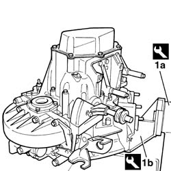
Engines: 2.0 16V, 2.0 JTD 8V, 2.3 JTD 16V, 2.8 JTD 8V
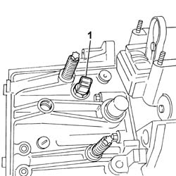
- PROCEED WITH DISMANTLING THE MANUAL GEARBOX CARRYING OUT THE OPERATIONS DESCRIBED BELOW.1. Undo and remove the reversing light switch.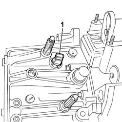
Engines: 2.0 16V, 2.0 JTD 8V, 2.3 JTD 16V, 2.8 JTD 8V
1. Undo the fixing bolts (1a) and remove the gearbox cover (1b).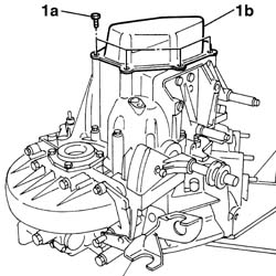
Engines: 2.0 16V, 2.0 JTD 8V, 2.3 JTD 16V, 2.8 JTD 8V
1. Remove the staking on the collar of the nut fastening the 5th speed driven gear.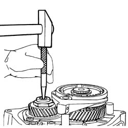
Engines: 2.0 16V, 2.0 JTD 8V, 2.3 JTD 16V, 2.8 JTD 8V
1. Extract the 5th speed engagement fork retaining pin.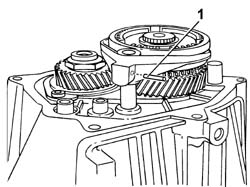
Engines: 2.0 16V, 2.0 JTD 8V, 2.3 JTD 16V, 2.8 JTD 8V
- Engage 5th speed manually and, using the gear selector lever, engage any gear at all. 1. Undo the nut (1b) fastening the 5th speed driven gear using the tool (1a).
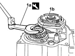
| [symbol: TOOLS 03.jpg] | Description | Code | Function |
|---|---|---|---|
| 1a | Spanner for removing/refitting 5th speed gear retaining nut | 1.870.405.000 | Dismantling 5th speed gear retaining nut |
Engines: 2.0 16V, 2.0 JTD 8V, 2.3 JTD 16V, 2.8 JTD 8V
1. Remove the 5th speed synchronizer retaining ring using special pliers.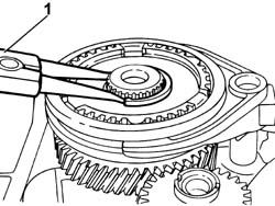
Engines: 2.0 16V, 2.0 JTD 8V, 2.3 JTD 16V, 2.8 JTD 8V
1. Position the tool for locking the 5th speed synchronizer.
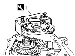
| [symbol: TOOLS 04.jpg] | Description | Code | Function |
|---|---|---|---|
| 1 | Tool for locking 5th speed synchronizer | 1.870.411.000 | Locking 5th speed synchronizer |
Engines: 2.0 16V, 2.0 JTD 8V, 2.3 JTD 16V, 2.8 JTD 8V
- Position the gear selector lever in neutral, then release the synchronizer and the 5th speed drive gear with the engagement fork.- Release the 5th speed driven gear.1. Undo the bolts fixing the layshaft bearing stop.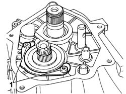
Engines: 2.0 16V, 2.0 JTD 8V, 2.3 JTD 16V, 2.8 JTD 8V
1. Loosen the bolts fixing the gearbox casing.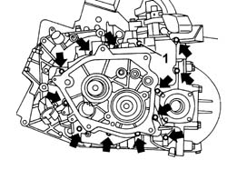
Engines: 2.0 16V, 2.0 JTD 8V, 2.3 JTD 16V, 2.8 JTD 8V
1. Loosen the fixing bolts.2. Release the gearbox casing and remove it.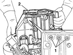
Engines: 2.0 16V, 2.0 JTD 8V, 2.3 JTD 16V, 2.8 JTD 8V
1. Remove the oil duct.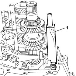
Engines: 2.0 16V, 2.0 JTD 8V, 2.3 JTD 16V, 2.8 JTD 8V
1. Remove the reverse gear and the shaft. 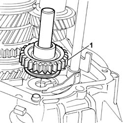
Engines: 2.0 16V, 2.0 JTD 8V, 2.3 JTD 16V, 2.8 JTD 8V
1. Release the pin fastening the reverse gear selector lever.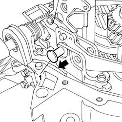
Engines: 2.0 16V, 2.0 JTD 8V, 2.3 JTD 16V, 2.8 JTD 8V
1. Remove the reverse gear selector lever complete with fork from the housing, releasing it in the direction shown by the arrow.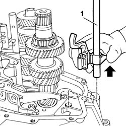
Engines: 2.0 16V, 2.0 JTD 8V, 2.3 JTD 16V, 2.8 JTD 8V
1. Undo the fixing bolts (1a) and remove the gear selector and engagement lever assembly (1b).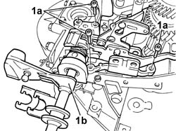
Engines: 2.0 16V, 2.0 JTD 8V, 2.3 JTD 16V, 2.8 JTD 8V
1. Extract the main and layshafts complete with gears from the housing.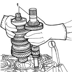
Engines: 2.0 16V, 2.0 JTD 8V, 2.3 JTD 16V, 2.8 JTD 8V
1. Extract the bell housing main shaft front bearing outer race (1a) using the tool (1b).
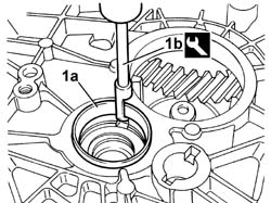
| [symbol: TOOLS 05.jpg] | Description | Code | Function |
|---|---|---|---|
| 1b | Main shaft front bearing outer race extractor | 1.846.011.000 | Main shaft front bearing outer race removal |
Engines: 2.0 16V, 2.0 JTD 8V, 2.3 JTD 16V, 2.8 JTD 8V
1. Extract the magnet from the seat and remove any metal particles that may be present.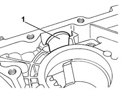
Engines: 2.0 16V, 2.0 JTD 8V, 2.3 JTD 16V, 2.8 JTD 8V
1. Remove the layshaft centering bush.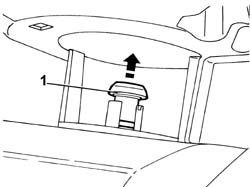
Engines: 2.0 16V, 2.0 JTD 8V, 2.3 JTD 16V, 2.8 JTD 8V
1. Undo the differential flange (1b) fixing bolts (1a).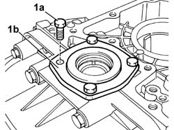
Engines: 2.0 16V, 2.0 JTD 8V, 2.3 JTD 16V, 2.8 JTD 8V
1. Remove the differential flange from the housing and extract the oil seal.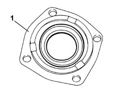
Engines: 2.0 16V, 2.0 JTD 8V, 2.3 JTD 16V, 2.8 JTD 8V
1. Undo the fixing bolt (1a) and remove the speed sensor support (1b).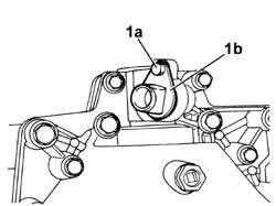
Engines: 2.0 16V, 2.0 JTD 8V, 2.3 JTD 16V, 2.8 JTD 8V
1. Undo the fixing bolts (1a) and remove the differential cover (1b).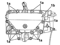
Engines: 2.0 16V, 2.0 JTD 8V, 2.3 JTD 16V, 2.8 JTD 8V
1. Remove the differential unit.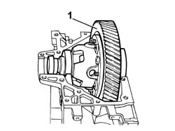
Engines: 2.0 16V, 2.0 JTD 8V, 2.3 JTD 16V, 2.8 JTD 8V
1. Undo the fixing bolts (1a) and release the thrust bearing sleeve (1b).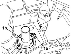
Engines: 2.0 16V, 2.0 JTD 8V, 2.3 JTD 16V, 2.8 JTD 8V
- PROCEED WITH DISMANTLING THE MAIN SHAFT CARRYING OUT THE OPERATIONS DESCRIBED BELOW.1. Position the main shaft in the vice, placing two types of protection in between.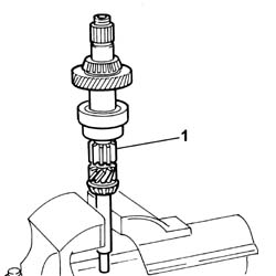
Engines: 2.0 16V, 2.0 JTD 8V, 2.3 JTD 16V, 2.8 JTD 8V
1. Extract the main shaft rear bearing.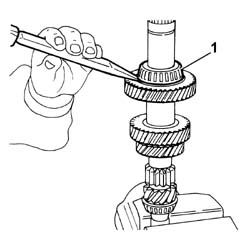
Engines: 2.0 16V, 2.0 JTD 8V, 2.3 JTD 16V, 2.8 JTD 8V
1. Extract the main shaft front bearing.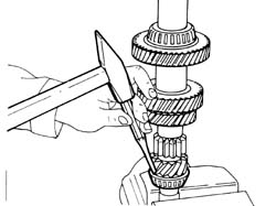
Engines: 2.0 16V, 2.0 JTD 8V, 2.3 JTD 16V, 2.8 JTD 8V
- PROCEED WITH DISMANTLING THE LAYSHAFT CARRYING OUT THE OPERATIONS DESCRIBED BELOW.1. Extract the front bearing (1d) and the 4th speed gear (1e) using tools (1a), (1b) and (1c).
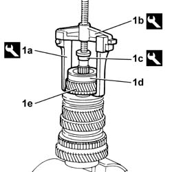
| [symbol: TOOLS 06.jpg] | Description | Code | Function |
|---|---|---|---|
| 1a | Feet for 1840005001 for dismantling layshaft front bearing | 1.840.005.302 | Dismantling layshaft front bearing |
| [symbol: TOOLS 07.jpg] | Description | Code | Function |
|---|---|---|---|
| 1b | Univeral extractor for dismantling layshaft bearing and differential bearings | 1.840.005.001 | Dismantling layshaft front bearing |
| [symbol: TOOLS 08.jpg] | Description | Code | Function |
|---|---|---|---|
| 1c | Flange for dismantling layshaft front bearing | 1.845.028.000 | Dismantling layshaft front bearing |
Engines: 2.0 16V, 2.0 JTD 8V, 2.3 JTD 16V, 2.8 JTD 8V
1. Release the 3rd and 4th speed synchronizer assembly.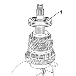
Engines: 2.0 16V, 2.0 JTD 8V, 2.3 JTD 16V, 2.8 JTD 8V
1. Remove the retaining seal.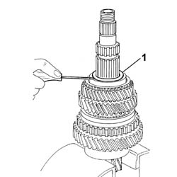
Engines: 2.0 16V, 2.0 JTD 8V, 2.3 JTD 16V, 2.8 JTD 8V
1. Release the 3rd speed gear.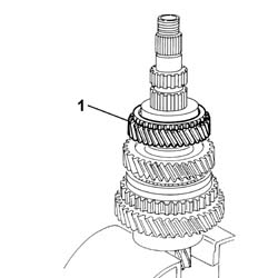
Engines: 2.0 16V, 2.0 JTD 8V, 2.3 JTD 16V, 2.8 JTD 8V
1. Remove the retaining seal.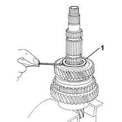
Engines: 2.0 16V, 2.0 JTD 8V, 2.3 JTD 16V, 2.8 JTD 8V
1. Release the 2nd speed gear.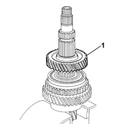
Engines: 2.0 16V, 2.0 JTD 8V, 2.3 JTD 16V, 2.8 JTD 8V
1. Release the 1st and 2nd speed synchronizer assembly and reverse gear.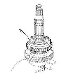
Engines: 2.0 16V, 2.0 JTD 8V, 2.3 JTD 16V, 2.8 JTD 8V
1. Remove the retaining seal.
Engines: 2.0 16V, 2.0 JTD 8V, 2.3 JTD 16V, 2.8 JTD 8V
1. Release the 1st speed gear.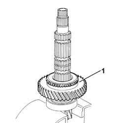
Engines: 2.0 16V, 2.0 JTD 8V, 2.3 JTD 16V, 2.8 JTD 8V
1. Remove the retaining seal.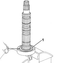
Engines: 2.0 16V, 2.0 JTD 8V, 2.3 JTD 16V, 2.8 JTD 8V
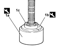
1. Extract the rear bearing (1c) on the press using tools (1a) and (1b).
| [symbol: TOOLS 09.jpg] | Description | Code | Function |
|---|---|---|---|
| 1a | Support for 1860946000 | 1.846.017.000 | Removing layshaft rear bearing |
| [symbol: TOOLS 10.jpg] | Description | Code | Function |
|---|---|---|---|
| 1b | Half flange for extracting layshaft rear bearing | 1.860.946.000 | Removing layshaft rear bearing |
Engines: 2.0 16V, 2.0 JTD 8V, 2.3 JTD 16V, 2.8 JTD 8V
- PROCEED WITH DISMANTLING THE REVERSE IDLER GEAR CARRYING OUT THE OPERATIONS DESCRIBED BELOW.1. Release the gear (1a) from the shaft (1b).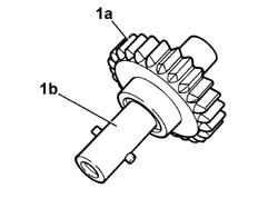
Engines: 2.0 16V, 2.0 JTD 8V, 2.3 JTD 16V, 2.8 JTD 8V
- Position the reverse gear in the vice, placing two types of protection in between.1. Extract the roller chamber (1a) from the toothed wheel (1b) using tool (1c).
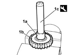
| [symbol: TOOLS 11.jpg] | Description | Code | Function |
|---|---|---|---|
| 1c | Tool for extracting-fitting reverse gear roller chamber | 1.870.421.000 | Extracting reverse gear roller chamber |
Engines: 2.0 16V, 2.0 JTD 8V, 2.3 JTD 16V, 2.8 JTD 8V
- PROCEED WITH DISMANTLING THE GEAR SELECTOR AND ENGAGEMENT LEVER ASSEMBLY CARRYING OUT THE OPERATIONS DESCRIBED BELOW.1. Separate the gear engagement levers from the assembly at the bench.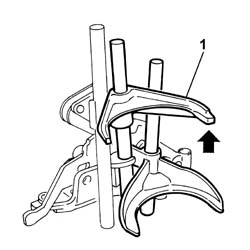
Engines: 2.0 16V, 2.0 JTD 8V, 2.3 JTD 16V, 2.8 JTD 8V
1. Release the fastening pin (1a) from the housing and remove the gear selector rod (1b) from the sleeve.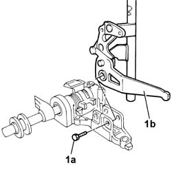
Engines: 2.0 16V, 2.0 JTD 8V, 2.3 JTD 16V, 2.8 JTD 8V
- Position the sleeve for the gear selector and engagement lever assembly in the vice placing two types of protection in between.1. Remove the fastening pin (1b) using a suitable diameter drift (1a).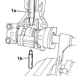
Engines: 2.0 16V, 2.0 JTD 8V, 2.3 JTD 16V, 2.8 JTD 8V
1. Undo the inner bolt (1a) and release the gear selector and engagement lever sleeve (1b).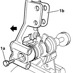
Engines: 2.0 16V, 2.0 JTD 8V, 2.3 JTD 16V, 2.8 JTD 8V
- Separate the gear selector and engagement lever assembly sleeve at the bench.1. Remove the pawl. 2. Remove the springs (2a) and (2b) from the housing.3. Remove the gasket.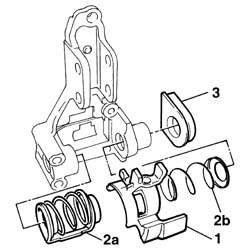
Engines: 2.0 16V, 2.0 JTD 8V, 2.3 JTD 16V, 2.8 JTD 8V
Refitting
- PROCEED WITH REASSEMBLING THE GEAR SELECTOR AND ENGAGEMENT LEVER ASSEMBLY CARRYING OUT THE OPERATIONS DESCRIBED BELOW.- Reassemble the gear selector and engagement lever assembly sleeve at the bench.1. Fit the springs (1a) and (1b) in place.2. Fit the pawl (2a) and the gasket (2b) in place.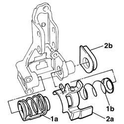
Engines: 2.0 16V, 2.0 JTD 8V, 2.3 JTD 16V, 2.8 JTD 8V
- Position the sleeve for the gear selector and engagement lever assembly in the vice placing two types of protection in between.1. Fit the gear selector and engagement lever assembly sleeve (1a) on the propeller shaft (1b).2. Tighten the fixing bolts.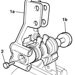
Engines: 2.0 16V, 2.0 JTD 8V, 2.3 JTD 16V, 2.8 JTD 8V
1. Place the fastening pin in position.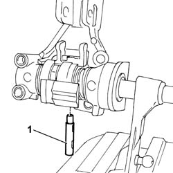
Engines: 2.0 16V, 2.0 JTD 8V, 2.3 JTD 16V, 2.8 JTD 8V
- Remove the gear selector and engagement lever assembly sleeve from the vice.1. Fit the gear selector rod (1a) in place on the sleeve and fastent it using the pin (1b).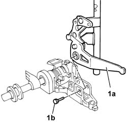
Engines: 2.0 16V, 2.0 JTD 8V, 2.3 JTD 16V, 2.8 JTD 8V
1. Fit the gear engagement levers in place on the assembly.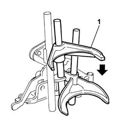
Engines: 2.0 16V, 2.0 JTD 8V, 2.3 JTD 16V, 2.8 JTD 8V
- PROCEED WITH REASSEMBLY OF THE REVERSE IDLER GEAR CARRYING OUT THE OPERATIONS DESCRIBED BELOW.- Position the reverse gear in the vice, placing two types of protection in between.1. Fit the roller chamber (1a) in position on the reverse gear (1b).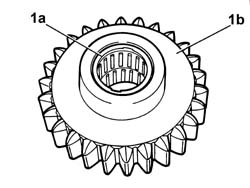
Engines: 2.0 16V, 2.0 JTD 8V, 2.3 JTD 16V, 2.8 JTD 8V
1. Fit the shaft (1a) in position on the reverse gear (1b).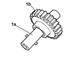
Engines: 2.0 16V, 2.0 JTD 8V, 2.3 JTD 16V, 2.8 JTD 8V
- PROCEED WITH REASSMBLING THE LAYSHAFT CARRYING OUT THE OPERATIONS DESCRIBED BELOW.1. Fit the layshaft (1b) rear bearing (1a) on the press.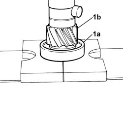
Engines: 2.0 16V, 2.0 JTD 8V, 2.3 JTD 16V, 2.8 JTD 8V
1. Position the layshaft in the vice, placing two types of protection in between.2. Fit the rear bearing circlip.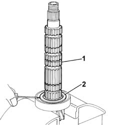
Engines: 2.0 16V, 2.0 JTD 8V, 2.3 JTD 16V, 2.8 JTD 8V
1. Fit the 1st speed gear in place.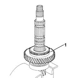
Engines: 2.0 16V, 2.0 JTD 8V, 2.3 JTD 16V, 2.8 JTD 8V
1. Fit the 1st speed gear circlip.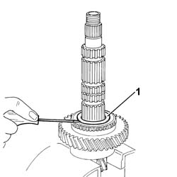
Engines: 2.0 16V, 2.0 JTD 8V, 2.3 JTD 16V, 2.8 JTD 8V
- PROCEED WITH THE REASSEMBLY OF THE 1ST AND 2ND SPEED SYNCHRONIZER COMPLETE WITH REVERSE GEAR CARRYING OUT THE OPERATIONS DESCRIBED BELOW.1. Fit the cylinders (1a) and thrust springs (1b) in the housings in the hub so that the projections (1c) on the actual cylinders are in line with the splining (1d) on the hub on both sides.2. Fit the sleeve (2a) so that the open section (2b) of the splining is opposite the projections on the cylinders.3. Position the balls on the cylinders and push them inside until the sleeve is completely inserted.4. Fit the seal (4a), the sleeve complete with hub and the synchronizer (4b) on the layshaft.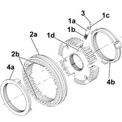
Engines: 2.0 16V, 2.0 JTD 8V, 2.3 JTD 16V, 2.8 JTD 8V
1. Check that the references for the synchronizers are aligned with the free balls.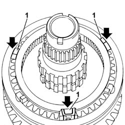
Engines: 2.0 16V, 2.0 JTD 8V, 2.3 JTD 16V, 2.8 JTD 8V
1. Fit the reverse gear.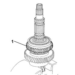
Engines: 2.0 16V, 2.0 JTD 8V, 2.3 JTD 16V, 2.8 JTD 8V
1. Fit the 2nd speed gear.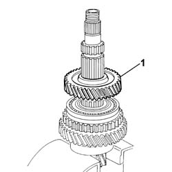
Engines: 2.0 16V, 2.0 JTD 8V, 2.3 JTD 16V, 2.8 JTD 8V
1. Fit the circlip.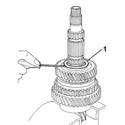
Engines: 2.0 16V, 2.0 JTD 8V, 2.3 JTD 16V, 2.8 JTD 8V
1. Fit the 3rd speed gear.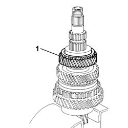
Engines: 2.0 16V, 2.0 JTD 8V, 2.3 JTD 16V, 2.8 JTD 8V
1. Fit the circlip.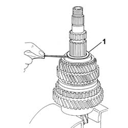
Engines: 2.0 16V, 2.0 JTD 8V, 2.3 JTD 16V, 2.8 JTD 8V
- PROCEED WITH REASSEMBLING THE 3RD AND 4TH SPEED SYNCHRONIZER CARRYING OUT THE OPERATIONS DESCRIBED BELOW.1. Fit the cylinders (1a) and thrust springs (1b) in the housings in the hub so that the projections (1c) on the actual cylinders are in line with the splining (1d) on the hub on both sides.2. Fit the sleeve (2a) so that the open section (2b) of the splining is opposite the projections on the cylinders.3. Position the balls on the cylinders and push them inside until the sleeve is completely inserted.4. Fit the seal (4a), the sleeve complete with hub and the synchronizer (4b) on the layshaft.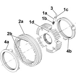
Engines: 2.0 16V, 2.0 JTD 8V, 2.3 JTD 16V, 2.8 JTD 8V
1. Check that the references for the synchronizers are aligned with the free balls.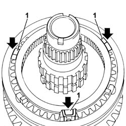
Engines: 2.0 16V, 2.0 JTD 8V, 2.3 JTD 16V, 2.8 JTD 8V
1. Fit the 4th speed gear.2. Fit the front bearing (2b) using the tool (2a).
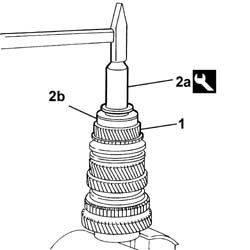
| [symbol: TOOLS 12.jpg] | Description | Code | Function |
|---|---|---|---|
| 2a | Tool for fitting layshaft front bearing | 1.875.082.000 | Fitting layshaft front bearing |
Engines: 2.0 16V, 2.0 JTD 8V, 2.3 JTD 16V, 2.8 JTD 8V
- PROCEED WITH REASSEMBLING THE MAIN SHAFT CARRYING OUT THE OPERATIONS DESCRIBED BELOW. Fit the 4th speed gear.1. Fit the front bearing (1a) using the tool (1b).
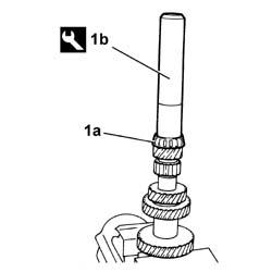
| [symbol: TOOLS 13.jpg] | Description | Code | Function |
|---|---|---|---|
| 1b | Tool for fitting main shaft front bearing | 1.860.945.000 | Fitting main shaft front bearing |
Engines: 2.0 16V, 2.0 JTD 8V, 2.3 JTD 16V, 2.8 JTD 8V
1. Fit the rear bearing (1a) using the tool (1b).
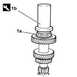
| [symbol: TOOLS 14.jpg] | Description | Code | Function |
|---|---|---|---|
| 1b | Tool for fitting main shaft rear bearing | 1.875.093.000 | Fitting main shaft rear bearing |
Engines: 2.0 16V, 2.0 JTD 8V, 2.3 JTD 16V, 2.8 JTD 8V
- PROCEED WITH REASSEMBLING THE MANUAL GEARBOX CARRYING OUT THE OPERATIONS DESCRIBED BELOW.1. Fit the sleeve (1a) for the thrust bearing and tighten the fixing bolts (1b) to torque.
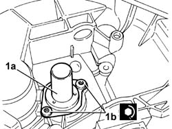
| [symbol: TORQUE 01.jpg] | Value - daNm | Fastening | Ø |
|---|---|---|---|
| 1b | 2 daNm | bolt |
Engines: 2.0 16V, 2.0 JTD 8V, 2.3 JTD 16V, 2.8 JTD 8V
1. Fit the differential unit in the bellhousing.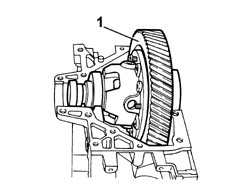
Engines: 2.0 16V, 2.0 JTD 8V, 2.3 JTD 16V, 2.8 JTD 8V
1. Fit the differential cover (1a) and tighten the fixing bolts (1 b) to the recommended torque.
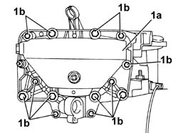
| [symbol: TORQUE 02.jpg] | Value - daNm | Fastening | Ø |
|---|---|---|---|
| 1b | 4 daNm | bolt | M10 |
| [symbol: TORQUE 03.jpg] | Value - daNm | Fastening | Ø |
|---|---|---|---|
| 1b | 2 daNm | bolt | M8 |
Engines: 2.0 16V, 2.0 JTD 8V, 2.3 JTD 16V, 2.8 JTD 8V
1. Fit the speed sensor support (1a) and tighten the fixing bolt (1b).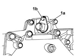
Engines: 2.0 16V, 2.0 JTD 8V, 2.3 JTD 16V, 2.8 JTD 8V
1. Fit the gasket on the differential flange using the tools (1a) and (1b).
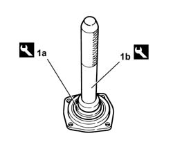
| [symbol: TOOLS 15.jpg] | Description | Code | Function |
|---|---|---|---|
| 1a | - | 1.870.426.000 | Fitting oil seal on differential flange |
| [symbol: TOOLS 16.jpg] | Description | Code | Function |
|---|---|---|---|
| 1b | Drift for 1870426000 | 1.870.007.000 | Fitting oil seal on differential flange |
Engines: 2.0 16V, 2.0 JTD 8V, 2.3 JTD 16V, 2.8 JTD 8V
1. Tighten the differential flange (1b) fixing bolts (1a) to torque.
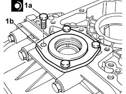
| [symbol: TORQUE 04.jpg] | Value - daNm | Fastening | Ø |
|---|---|---|---|
| 1a | 2 daNm | bolt | - |
Engines: 2.0 16V, 2.0 JTD 8V, 2.3 JTD 16V, 2.8 JTD 8V
1. Fit the layshaft centering bush.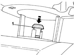
Engines: 2.0 16V, 2.0 JTD 8V, 2.3 JTD 16V, 2.8 JTD 8V
1. Fit the magnet in position.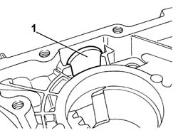
Engines: 2.0 16V, 2.0 JTD 8V, 2.3 JTD 16V, 2.8 JTD 8V
1. Fit the main shaft front bearing outer race in position using the tools (1a) and (1b).
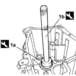
| [symbol: TOOLS 17.jpg] | Description | Code | Function |
|---|---|---|---|
| 1a | Tool for extracting-fitting main shaft rear bearing outer race | 1.860.957.000 | Fitting main shaft rear bearing outer race |
| [symbol: TOOLS 18.jpg] | Description | Code | Function |
|---|---|---|---|
| 1b | Drift for 1860957000 | 1.874.365.000 | Fitting main shaft rear bearing outer race |
Engines: 2.0 16V, 2.0 JTD 8V, 2.3 JTD 16V, 2.8 JTD 8V
1. Rest the main shaft on the bellhousing.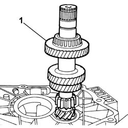
Engines: 2.0 16V, 2.0 JTD 8V, 2.3 JTD 16V, 2.8 JTD 8V
1. Fit the gearbox casing securing it using half the bolts.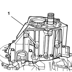
Engines: 2.0 16V, 2.0 JTD 8V, 2.3 JTD 16V, 2.8 JTD 8V
1. Position a dial gauge resting the magnetic part on the differential flange.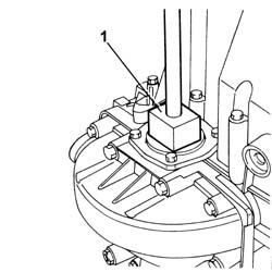
Engines: 2.0 16V, 2.0 JTD 8V, 2.3 JTD 16V, 2.8 JTD 8V
1. Fit the tool and measure the main shaft endfloat.
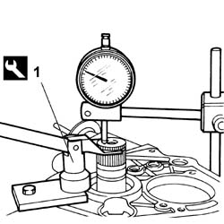
| [symbol: TOOLS 19.jpg] | Description | Code | Function |
|---|---|---|---|
| 1 | Fork for measuring main shaft clearance | 1.860.956.000 | Measuring main shaft clearance |
| [symbol: MEASURE 01.jpg] | Subject | Value |
|---|---|---|
| - | endfloat | mm 0.05 - 0.15 |
Engines: 2.0 16V, 2.0 JTD 8V, 2.3 JTD 16V, 2.8 JTD 8V
- Remove the tools and the bellhousing.1. Fit the main and layshafts in position.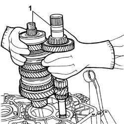
Engines: 2.0 16V, 2.0 JTD 8V, 2.3 JTD 16V, 2.8 JTD 8V
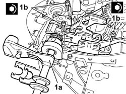
1. Fit the gear selector and engagement lever assembly (1a) and tighten the fixing bolts (1b) to torque.
| [symbol: TORQUE 05.jpg] | Value - daNm | Fastening | Ø |
|---|---|---|---|
| 1b | 1.5 daNm | bolt | - |
Engines: 2.0 16V, 2.0 JTD 8V, 2.3 JTD 16V, 2.8 JTD 8V
1. Fit the reverse gear selector lever complete with fork in position.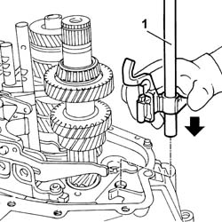
Engines: 2.0 16V, 2.0 JTD 8V, 2.3 JTD 16V, 2.8 JTD 8V
1. Fit the pin fastening the reverse gear selector lever in place.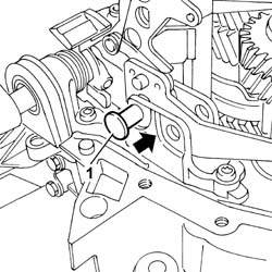
Engines: 2.0 16V, 2.0 JTD 8V, 2.3 JTD 16V, 2.8 JTD 8V
1. Fit the reverse gear and the shaft. 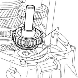
Engines: 2.0 16V, 2.0 JTD 8V, 2.3 JTD 16V, 2.8 JTD 8V
1. Fit the oil duct.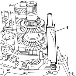
Engines: 2.0 16V, 2.0 JTD 8V, 2.3 JTD 16V, 2.8 JTD 8V
1. Fit the gearbox casing2. Tighten the fixing bolts.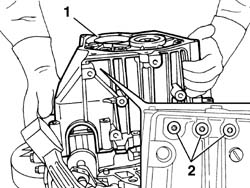
Engines: 2.0 16V, 2.0 JTD 8V, 2.3 JTD 16V, 2.8 JTD 8V
1. Tighten the gearbox casing fixing bolts to torque.
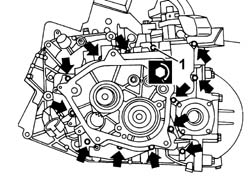
| [symbol: TORQUE 06.jpg] | Value - daNm | Fastening | Ø |
|---|---|---|---|
| 1 | 2 daNm | bolt | - |
Engines: 2.0 16V, 2.0 JTD 8V, 2.3 JTD 16V, 2.8 JTD 8V
1. Tighten the bolts fixing the layshaft bearing stop to torque.
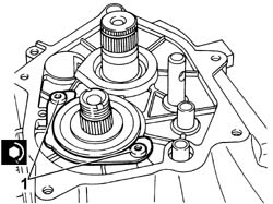
| [symbol: TORQUE 07.jpg] | Value - daNm | Fastening | Ø |
|---|---|---|---|
| 1 | 2 daNm | bolt | - |
Engines: 2.0 16V, 2.0 JTD 8V, 2.3 JTD 16V, 2.8 JTD 8V
- Fit the 5th speed drive gear on the main shaft.- Fit the 5th speed driven gear on the layshaft.1. Tighten the nut (1a) fastening the 5th speed driven gear using the tool (1b).
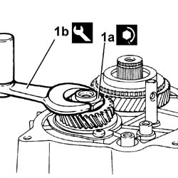
| [symbol: TORQUE 08.jpg] | Value - daNm | Fastening | Ø |
|---|---|---|---|
| 1a | 17 daNm | bolt | - |
| [symbol: TOOLS 20.jpg] | Description | Code | Function |
|---|---|---|---|
| 1b | Spanner for removing/refitting 5th speed gear retaining nut | 1.870.405.000 | Dismantling 5th speed gear retaining nut |
Engines: 2.0 16V, 2.0 JTD 8V, 2.3 JTD 16V, 2.8 JTD 8V
- Stake the nut fixing the 5th speed driven gear.1. Fit the 5th speed synchronizer (1b) and engagement fork on the main shaft using the tool (1a) and secure it using the circlip.
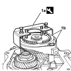
| [symbol: TOOLS 21.jpg] | Description | Code | Function |
|---|---|---|---|
| 1a | Tool for locking 5th speed synchronizer | 1.870.411.000 | locking 5th speed synchronizer |
Engines: 2.0 16V, 2.0 JTD 8V, 2.3 JTD 16V, 2.8 JTD 8V
1. Fit the 5th speed engagement fork retaining pin.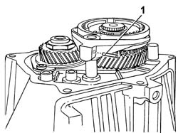
Engines: 2.0 16V, 2.0 JTD 8V, 2.3 JTD 16V, 2.8 JTD 8V
1. Fit the gearbox cover (1a) and tighten the fixing bolts (1 b) to the recommended torque.
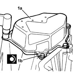
| [symbol: TORQUE 09.jpg] | Value - daNm | Fastening | Ø |
|---|---|---|---|
| 1b | 2 daNm | bolt | - |
Engines: 2.0 16V, 2.0 JTD 8V, 2.3 JTD 16V, 2.8 JTD 8V
1. Tighten the reversing lights switch