Procedures
2110D10 DIFFERENTIAL INNER CASE - R + R WITH MANUAL GEARBOX REMOVED - INCLUDES GEARBOX DISMANTLE AND REBUILD
Engines: 2.0 16V, 2.0 JTD 8V, 2.3 JTD 16V, 2.8 JTD 8V
Removing
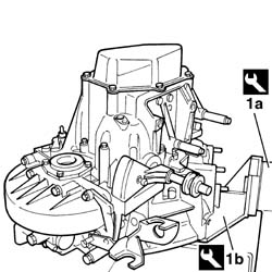
1. Arrange the gearbox on rotary stand (1a) using stand (1b).
| [symbol: TOOLS 01.jpg] | Description | Code | Function |
|---|---|---|---|
| 1a | Rotary stand used to support the gearbox | 1.871.000.000 | Secure the gearbox for dismantling |
| [symbol: TOOLS 02.jpg] | Description | Code | Function |
|---|---|---|---|
| 1b | Stand for 1871000000 | 1.871.001.014 | Stand used to secure the gearbox for dismantling |
Engines: 2.0 16V, 2.0 JTD 8V, 2.3 JTD 16V, 2.8 JTD 8V
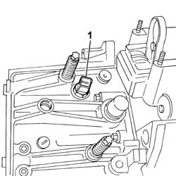
- DISMANTLE THE MANUAL GEARBOX BY CARRYING OUT THE OPERATIONS DESCRIBED BELOW.1. Undo and remove the reversing light switch.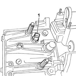
Engines: 2.0 16V, 2.0 JTD 8V, 2.3 JTD 16V, 2.8 JTD 8V
1. Undo the fixing bolts (1a) and remove the gearbox cover (1b).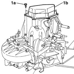
Engines: 2.0 16V, 2.0 JTD 8V, 2.3 JTD 16V, 2.8 JTD 8V
1. Remove the staking on the collar of the nut securing the 5th speed driven gear.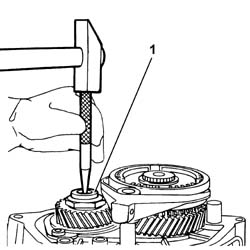
Engines: 2.0 16V, 2.0 JTD 8V, 2.3 JTD 16V, 2.8 JTD 8V
1. Remove the pin securing the 5th speed engagement fork.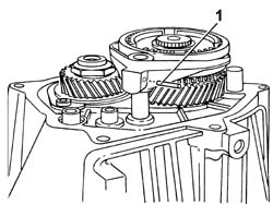
Engines: 2.0 16V, 2.0 JTD 8V, 2.3 JTD 16V, 2.8 JTD 8V
- Insert 5th speed by hand and use the gear selection lever to select any gear.1. Use tool (1a) to unscrew the nut (1b) securnig the 5th speed driven gear.
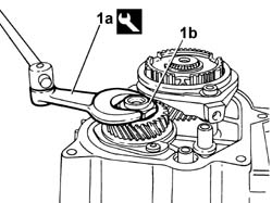
| [symbol: TOOLS 03.jpg] | Description | Code | Function |
|---|---|---|---|
| 1a | Wrench used to remove/refit the 5th speed retaining nut | 1.870.405.000 | Removing the 5th speed gear retaining nut |
Engines: 2.0 16V, 2.0 JTD 8V, 2.3 JTD 16V, 2.8 JTD 8V
1. Use round-nosed pliers to remove the 5th speed synchroniser retaining ring.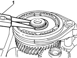
Engines: 2.0 16V, 2.0 JTD 8V, 2.3 JTD 16V, 2.8 JTD 8V
1. Position the tool to lock the 5th speed synchroniser.
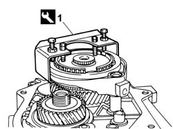
| [symbol: TOOLS 04.jpg] | Description | Code | Function |
|---|---|---|---|
| 1 | Tool used to lock the 5th speed synchroniser | 1.870.411.000 | Lock the 5th speed synchroniser |
Engines: 2.0 16V, 2.0 JTD 8V, 2.3 JTD 16V, 2.8 JTD 8V
- Move the gear selection lever to neutral, then withdraw the synchroniser and 5th speed drive gear with the engagement fork.- Withdraw the 5th speed driven gear.1. Withdraw the bolts securing the layshaft bearing detent.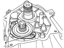
Engines: 2.0 16V, 2.0 JTD 8V, 2.3 JTD 16V, 2.8 JTD 8V
1. Tighten the bolts fixing the gearbox.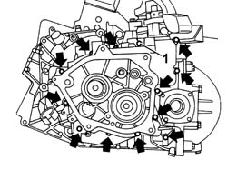
Engines: 2.0 16V, 2.0 JTD 8V, 2.3 JTD 16V, 2.8 JTD 8V
1. Loosen the fixing bolts.2. Withdraw the gear casing and remove.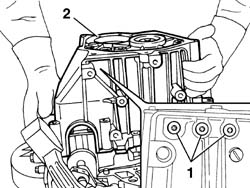
Engines: 2.0 16V, 2.0 JTD 8V, 2.3 JTD 16V, 2.8 JTD 8V
1. Remove the oil channel.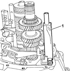
Engines: 2.0 16V, 2.0 JTD 8V, 2.3 JTD 16V, 2.8 JTD 8V
1. Remove the reverse shaft and gear.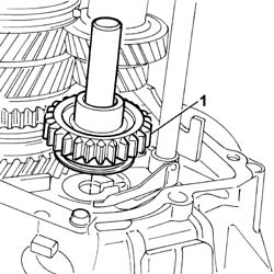
Engines: 2.0 16V, 2.0 JTD 8V, 2.3 JTD 16V, 2.8 JTD 8V
1. Withdraw the gear selection lever pin.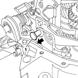
Engines: 2.0 16V, 2.0 JTD 8V, 2.3 JTD 16V, 2.8 JTD 8V
1. Remove the reverse selection lever with fork from its seat by withdrawing in the arrowed direction.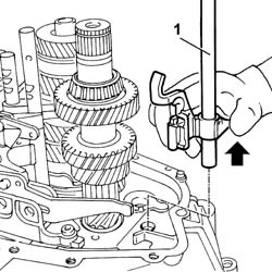
Engines: 2.0 16V, 2.0 JTD 8V, 2.3 JTD 16V, 2.8 JTD 8V
1. Unscrew retaining bolts (1a) and remove the gear selection and engagement lever assembly (1b).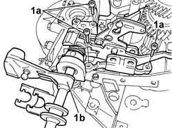
Engines: 2.0 16V, 2.0 JTD 8V, 2.3 JTD 16V, 2.8 JTD 8V
1. Remove the main and layshafts from their seat with gears.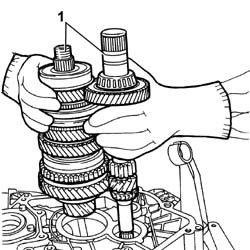
Engines: 2.0 16V, 2.0 JTD 8V, 2.3 JTD 16V, 2.8 JTD 8V
1. Undo the bolts (1a) securing differential flange (1b).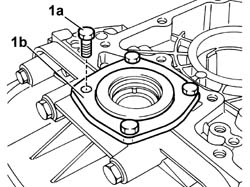
Engines: 2.0 16V, 2.0 JTD 8V, 2.3 JTD 16V, 2.8 JTD 8V
1. Remove the differential flange from its seat and take out the oil seal.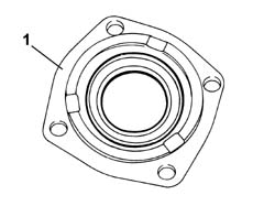
Engines: 2.0 16V, 2.0 JTD 8V, 2.3 JTD 16V, 2.8 JTD 8V
1. Undo the fixing bolt (1a) and remove the detonation sensor mount (1b).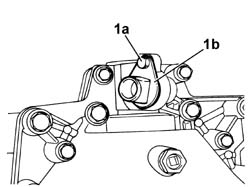
Engines: 2.0 16V, 2.0 JTD 8V, 2.3 JTD 16V, 2.8 JTD 8V
1. Undo the fixing bolts (1a) and remove the differential cover (1b).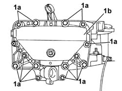
Engines: 2.0 16V, 2.0 JTD 8V, 2.3 JTD 16V, 2.8 JTD 8V
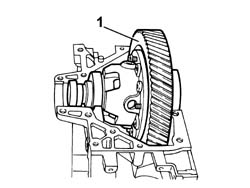
1. Remove the differential unit.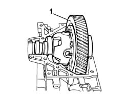
Engines: 2.0 16V, 2.0 JTD 8V, 2.3 JTD 16V, 2.8 JTD 8V
Engines: 2.0 16V, 2.0 JTD 8V, 2.3 JTD 16V, 2.8 JTD 8V
1. Fit the differential cover (1a) and tighten the fixing bolts (1b) to the recommended torque.
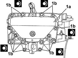
| [symbol: TORQUE 01.jpg] | Value - daNm | Fastening | Component | Ø |
|---|---|---|---|---|
| 1b | 4 daNm | bolt | M10 |
| [symbol: TORQUE 02.jpg] | Value - daNm | Fastening | Component | Ø |
|---|---|---|---|---|
| 1b | 2 daNm | bolt | M8 |
Engines: 2.0 16V, 2.0 JTD 8V, 2.3 JTD 16V, 2.8 JTD 8V
1. Fit speed sensor mount (1a) and tighten bolt (1b).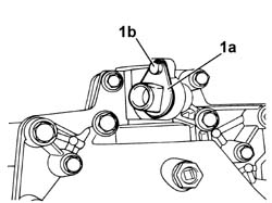
Engines: 2.0 16V, 2.0 JTD 8V, 2.3 JTD 16V, 2.8 JTD 8V
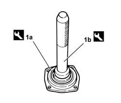
1. Fit the gasket to the differential flange using tools (1a) and (1b).
| [symbol: TOOLS 05.jpg] | Description | Code | Function |
|---|---|---|---|
| 1a | - | 1.870.426.000 | Fitting oil seal to the differential flange |
| [symbol: TOOLS 06.jpg] | Description | Code | Function |
|---|---|---|---|
| 1b | Drift for 1870426000 | 1.870.007.000 | Fitting oil seal to the differential flange |
Engines: 2.0 16V, 2.0 JTD 8V, 2.3 JTD 16V, 2.8 JTD 8V
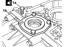
1. tighten the bolts (1a) securing differential flange (1b) to torque.
| [symbol: TORQUE 03.jpg] | Value - daNm | Fastening | Component | Ø |
|---|---|---|---|---|
| 1a | 2 daNm | bolt | - | - |
Engines: 2.0 16V, 2.0 JTD 8V, 2.3 JTD 16V, 2.8 JTD 8V
1. Rest the mainshaft on the gearbox bell housing.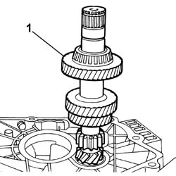
Engines: 2.0 16V, 2.0 JTD 8V, 2.3 JTD 16V, 2.8 JTD 8V
1. Fit the gear casing and secure with half the bolts.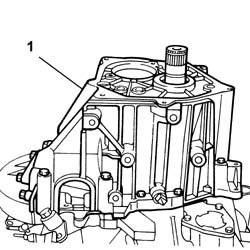
Engines: 2.0 16V, 2.0 JTD 8V, 2.3 JTD 16V, 2.8 JTD 8V
1. Position a dial gauge by resting the magnetic part on the differential flange.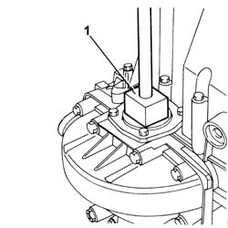
Engines: 2.0 16V, 2.0 JTD 8V, 2.3 JTD 16V, 2.8 JTD 8V
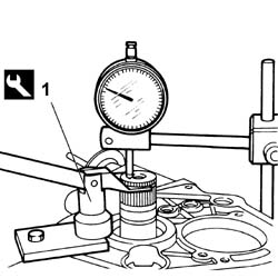
1. Fit the tool and measure the mainshaft end float.
| [symbol: TOOLS 07.jpg] | Description | Code | Function |
|---|---|---|---|
| 1 | Fork for measuring mainshaft end float | 1.860.956.000 | Measuring mainshaft end float. |
| [symbol: MEASURE 01.jpg] | Subject | Value |
|---|---|---|
| - | end float | 0.05 - 0.15 mm |
Engines: 2.0 16V, 2.0 JTD 8V, 2.3 JTD 16V, 2.8 JTD 8V
- Remove the tools and the gearbox bell housing.1. Fit the mainshaft and layshaft in their seats.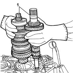
Engines: 2.0 16V, 2.0 JTD 8V, 2.3 JTD 16V, 2.8 JTD 8V
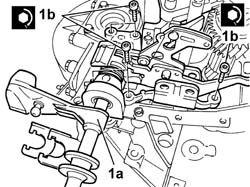
1. Fit the gear selection and engagement lever assembly (1a) and tighten the bolts (1b) to torque.
| [symbol: TORQUE 04.jpg] | Value - daNm | Fastening | Component | Ø |
|---|---|---|---|---|
| 1b | 1.5 daNm | bolt | - | - |
Engines: 2.0 16V, 2.0 JTD 8V, 2.3 JTD 16V, 2.8 JTD 8V
1. Fit the reversing selection lever with fork in its seat.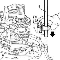
Engines: 2.0 16V, 2.0 JTD 8V, 2.3 JTD 16V, 2.8 JTD 8V
1. Fit the reverse selection lever pin into its seat.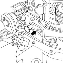
Engines: 2.0 16V, 2.0 JTD 8V, 2.3 JTD 16V, 2.8 JTD 8V
1. Fit the reverse shaft and gear.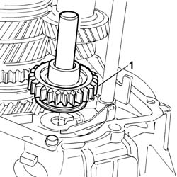
Engines: 2.0 16V, 2.0 JTD 8V, 2.3 JTD 16V, 2.8 JTD 8V
1. Fit the oil channel.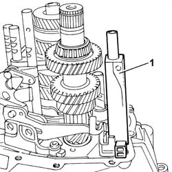
Engines: 2.0 16V, 2.0 JTD 8V, 2.3 JTD 16V, 2.8 JTD 8V
1. Fit the gear casing2. Tighten the fixing bolts.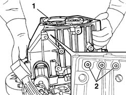
Engines: 2.0 16V, 2.0 JTD 8V, 2.3 JTD 16V, 2.8 JTD 8V
1. Tighten the gear casing retaining bolts to torque.
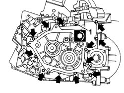
| [symbol: TORQUE 05.jpg] | Value - daNm | Fastening | Component | Ø |
|---|---|---|---|---|
| 1 | 2 daNm | bolt | - | - |
Engines: 2.0 16V, 2.0 JTD 8V, 2.3 JTD 16V, 2.8 JTD 8V
1. Tighten the bolts securing the layshaft bearing detent to torque.
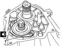
| [symbol: TORQUE 06.jpg] | Value - daNm | Fastening | Component | Ø |
|---|---|---|---|---|
| 1 | 2 daNm | bolt | - | - |
Engines: 2.0 16V, 2.0 JTD 8V, 2.3 JTD 16V, 2.8 JTD 8V
- Fit the 5th speed drive gear to the mainshaft.- Fit the 5th speed driven gear to the layshaft.1. Tighten nut (1a) securing the 5th speed driven gear using tool (1b).
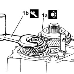
| [symbol: TORQUE 07.jpg] | Value - daNm | Fastening | Component | Ø |
|---|---|---|---|---|
| 1a | 17 daNm | bolt | - | - |
| [symbol: TOOLS 08.jpg] | Description | Code | Function |
|---|---|---|---|
| 1b | Wrench used to remove/refit the 5th speed retaining nut | 1.870.405.000 | Removing the 5th speed gear retaining nut |
Engines: 2.0 16V, 2.0 JTD 8V, 2.3 JTD 16V, 2.8 JTD 8V
- Chamfer the nut securing the 5th driven gear.1. Use tool (1a) to install the 5th speed synchroniser (1b) with its engagement fork to the mainshaft and secure with the retaining ring.
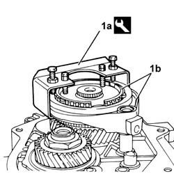
| [symbol: TOOLS 09.jpg] | Description | Code | Function |
|---|---|---|---|
| 1a | Tool used to lock the 5th speed synchroniser | 1.870.411.000 | locking the 5th speed synchroniser |
Engines: 2.0 16V, 2.0 JTD 8V, 2.3 JTD 16V, 2.8 JTD 8V
1. Fit the pin securing the 5th speed engagement fork.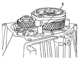
Engines: 2.0 16V, 2.0 JTD 8V, 2.3 JTD 16V, 2.8 JTD 8V
1. Fit the gearbox cover (1a) and tighten the fixing bolts (1b) to the recommended torque.
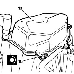
| [symbol: TORQUE 08.jpg] | Value - daNm | Fastening | Component | Ø |
|---|---|---|---|---|
| 1b | 2 daNm | bolt | - | - |
Engines: 2.0 16V, 2.0 JTD 8V, 2.3 JTD 16V, 2.8 JTD 8V
1. Tighten the brake light switch