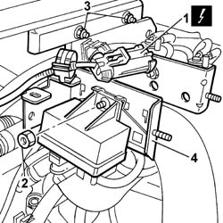
2. Undo the nut fixing the heater plugs control unit.3. Undo the nuts fixing the bracket to the partition.4. Move the bracket complete with solenoid valves and heater plugs control unit to the side.
Engines: 2.0 JTD 8V
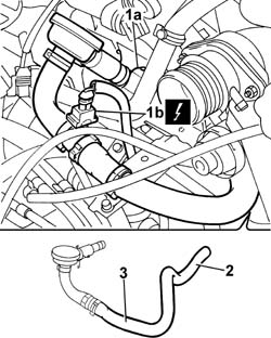
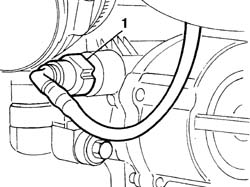
1. Press the retaining spring (1a) and disconnect the electrical connection (1b) for the engine oil vapour pipe.
Description
Connector
1b
Oil vapour heating resistance
O007A
2. Disconnect the engine oil vapour pipe from the air intake pipe between the filter and the turbocharger.3. Remove the oil vapour pipe.
Engines: 2.0 JTD 8V
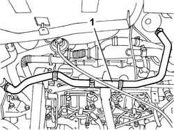
1. Open the bands and release the heater coolant pipe.
Engines: 2.0 JTD 8V
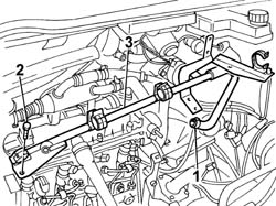
1. Disconnect the recirculation pipe from the thermostat.2. Undo the fixing bolts at the ends of the rigid pipe.- Disconnect the coolant reservoir recirculation pipe from the rigid pipe.3. Remove the rigid pipe from the housing.
Engines: 2.0 JTD 8V
1. Disconnect the vacuum pipe from the brake servo.
Engines: 2.0 JTD 8V
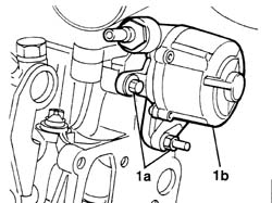
1. Undo the fixing bolts (1a) and remove the vacuum unit (1b) from the housing in the cylinder head.
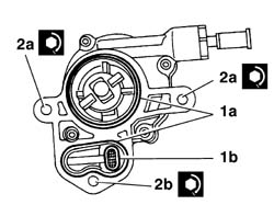
1. Lubricate and, if necessary, replace the seals (1a) and the oil filter (1b).2. Fit the vacuum unit and tighten the bolts (2a) and the nut (2b) to the recommended torque.
Value - daNm
Fastening
Component
Ø
2a
4,3
Bolt
BRAKING SYSTEM BRAKES
-
Value - daNm
Fastening
Component
Ø
2b
4,3
Nut
BRAKING SYSTEM BRAKES
-
Engines: 2.0 JTD 8V
- Connect the vacuum pipe to the brake servo.- Fit the rigid pipe in the housing on the cylinder head.- Connect the coolant reservoir recirculation pipe to the rigid pipe and tighten the fixing bolts.- Connect the recirculation pipe to the thermostat.- Position the heater coolant pipe.- Connect the electrical connection for the engine oil vapour pipe.
Description
Connector
.
Oil vapour heating resistance
O007A
- Connect the engine oil vapour pipe to the air intake pipe between the filter and the turbocharger and to the tappet cover.- Fit the bracket complete with solenoid valves and heater plugs control unit.- Tighten the nut fixing the heater plugs control unit.- Connect the electrical connection for the heater plugs control unit.
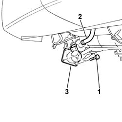
Op. 7055B54 UNDER-ENGINE GUARD - R R1. Undo the fixing bolts.2. Open the band and disconnect the pipe from the vacuum unit.3. Remove the vacuum unit from the lower part of the engine compartment.