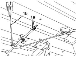
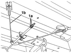
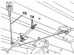
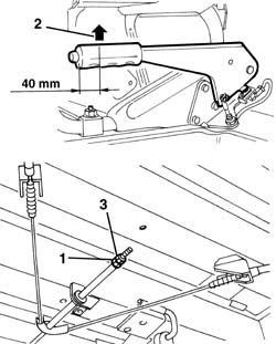
Position the vehicle on the lift.Remove both the rear wheels.1. Working underneath the vehicle, loosen the handbrake adjustment nuts (1a), until the cable (1b) is slack.
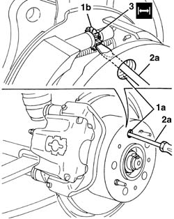
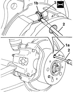
Carry out the following three stages on both sides of the vehicle.1. Rotate the brake disc manually until one of the openings (1a) is in line with the toothed pin (1b) for the clearance recovery device.2. Insert a screwdriver (2a) and, with the assistance of an electric torch, rotate the toothed pin upwards until the end of travel position (a condition in which the shoes are touching the brake drum).3. Rotate the toothed pin (1b) by about 10 teeth in the opposite direction (downwards). This operation allows the correct clearance between the shoes and the drum to be re-established (the rotation of one of the teeth for the clearance recovery device toothed pin corresponds to a variation of 0.035 mm in the shoe diameter).
[symbol: MEASURE 01.jpg]
Subject
Value
3
Rear shoe adjustment device (Clearance between shoes and drum)
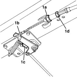
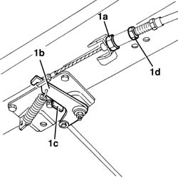
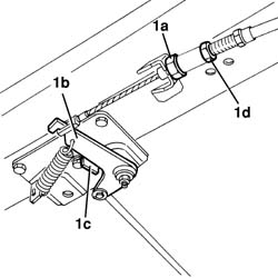
1. With the handbrake lever in the rest position, work underneath the vehicle and tighten the adjustment nut (1a) until the lever (1b) slowly becomes detached from the end of travel position on the bracket (1c); then lock the locknut (1d).
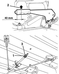
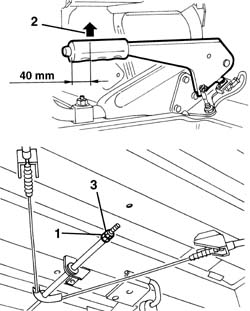
Place the handbrake lever at the third notch starting from the rest position.1. Working underneath the vehicle, tighten the adjustment nut.
[symbol: 774.jpg]
Value - daNm
Fastening
Component
Ø
1
0.25
Nut
HANDBRAKE CABLE ADJUSTMENT DEVICE
-
2. Check that when the handbrake lever is at the fourth notch the load on the grip is about 25 Kg, otherwise adjust the adjustment nut (1a) until the load is correct.3. Tighten the locknut.
Position the vehicle on the lift.Remove both the rear wheels.1. Working underneath the vehicle, loosen the handbrake adjustment nuts (1a), until the cable (1b) is slack.
1. With the handbrake lever in the rest position, work underneath the vehicle and tighten the adjustment nut (1a) until the lever (1b) slowly becomes detached from the end of travel position on the bracket (1c); then lock the locknut (1d).
Place the handbrake lever at the third notch starting from the rest position.1. Working underneath the vehicle, tighten the adjustment nut.
[symbol: 774_1.jpg]
Value - daNm
Fastening
Component
Ø
1
0.25
Nut
HANDBRAKE CABLE ADJUSTMENT DEVICE
-
2. Check that when the handbrake lever is at the fourth notch the load on the grip is about 25 Kg, otherwise adjust the adjustment nut (1a) until the load is correct.3. Tighten the locknut.
- Position the vehicle on the lift.- Remove both the rear wheels1. Working underneath the vehicle, loosen the handbrake adjustment nuts (1a), until the cable (1b) is slack.
- Carry out the following three stages on both sides of the vehicle.1. Rotate the brake disc manually until one of the openings (1a) is in line with the toothed pin (1b) for the clearance recovery device.2. Insert a screwdriver and, with the assistance of an electric torch, rotate the toothed pin upwards until the end of travel position (a condition in which the shoes are touching the brake drum).3. Rotate the toothed wheel (1b) by about 5 teeth in the opposite direction (downwards). This operation makes it possible to re-establish the recommended clearance between the shoes and the drum (the rotation of five teeth of the adjustment wheel corresponds to a variation in the shoe diameter of 0.15 mm). The disc thereby rotates without sticking but can produce a certain resistance.
1. With the handbrake lever in the rest position, work underneath the vehicle and tighten the adjustment nut (1a) until the lever (1b) slowly becomes detached from the end of travel position on the bracket (1c); then lock the locknut (1d).
- Place the handbrake lever at the third notch starting from the rest position.1. Working underneath the vehicle, tighten the adjustment nut.
[symbol: TORQUE 01.jpg]
Value - daNm
Fastening
Component
Ø
1
0.25
nut
2. Check that when the handbrake lever is at the fourth notch the load on the grip is about 33 Kg, otherwise adjust the adjustment nut (1a) until the load is correct.3. Tighten the locknut.