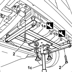
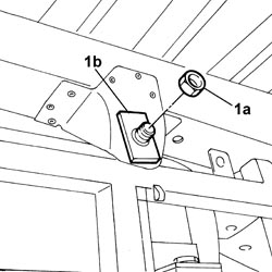
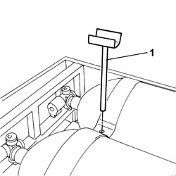
1. Undo the front fixing nuts (1a) and keep the special washers (1b).
Engines: 2.0 16V
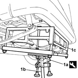
Bend the connecting pipe between the rear canisters and the rear connector inwards.1. Working on the tool (1a) and the hydraulic lift (1b), retract the frame complete with canisters (1c) and tilt it backwards until it is removed from the vehicle.
[symbol: attrezzi.tif]
Description
Code
Function
1a
Adjustable plate
1.870.856.000
Removing-refitting additional canisters
Engines: 2.0 16V
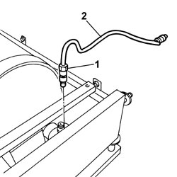
1. Undo the connector on the solenoid valve.2. Remove the connecting pipe between the additional canister and the rear connector.
Engines: 2.0 16V
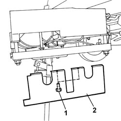
1. Undo the retaining bolts.2. Remove the shield.
Engines: 2.0 16V
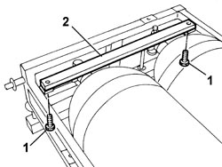
1. Undo the retaining bolts.2. Remove the shield mounting bracket.
Engines: 2.0 16V
1. Undo the connectors on the solenoid valves.2. Remove the additional canisters connecting pipe.
Engines: 2.0 16V
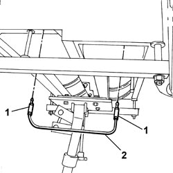
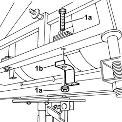
1. Remove the lower nuts fixing belt anchorage rods and the washers.2. Keep the canister guard mounting brackets.
Engines: 2.0 16V
1. Remove the belt anchorage rods.
Engines: 2.0 16V
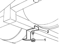
1. Undo the fixing bolts (1a) and keep the canister guard mounting brackets (1b).
Engines: 2.0 16V
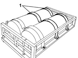
1. Remove the upper belts securing the centre and solenoid valve side canisters.
Engines: 2.0 16V
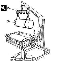
1. Release the upper belt at the side.2. Using the special tool and suitable cables, secure the canister.
[symbol: attrezzi.tif]
Description
Code
Function
2
Tool for balancing
1.871.001.700
Removing-refitting additional canisters from frame
3. Using the hydraulic lift, remove the canister from the support frame.Carry out similar operations to remove the remaining canister.Remove the remaining upper belt and the lower belts.Remove the frame from the support tool.
Position the canister support frame on the tools secured to the hydraulic lift.
[symbol: attrezzi.tif]
Description
Code
Function
-
Frame for removing-refitting additional canisters
2.000.000.000
Removing-refitting additional canisters
[symbol: attrezzi.tif]
Description
Code
Function
-
Adjustable plate
1.870.856.000
Removing-refitting additional canisters
Position the lower fixing belts.Position the upper belt on the support frame to allow the positioning of the canisters.Using the special tool and suitable cables, secure the canister.
[symbol: attrezzi.tif]
Description
Code
Function
2
Tool for balancing
1.871.001.700
Removing-refitting additional canisters from frame
Using the hydraulic lift, position the canister on the support frame.Carry out similar operations to position the remaining canister.Position the additional canisters connecting pipe and tighten the connectors on the solenoid valves to the recommended torque.
[symbol: coppie.tif]
Value daNm
Fastening
Component
Ø
-
2.8
Connector
-
-
Position the remaining fixing belts.Fit the canister guard mounting brackets making sure they are in the position marked on their removal and tighten the fixing bolts.Fit the belt anchorage rods.Fit the canister guard mounting brackets making sure they are in the position marked on their removal and tighten the nuts with washers.Position the guard mounting bracket and tighten the fixing bolts.Position the guard and tighten the fixing bolts.Position the connecting pipe between the additional canister and the rear connector and tighten the connector on the solenoid valve to the recommended torque.
[symbol: coppie.tif]
Value daNm
Fastening
Component
Ø
-
2.8
Connector
-
-
Working on the support ool and the hydraulic lift, place the frame complete with canisters in position on the vehicle taking care not to damage the connecting pipe between the canisters and the rear connector.
[symbol: attrezzi.tif]
Description
Code
Function
-
Frame for removing-refitting additional canisters
2.000.000.000
Removing-refitting additional canisters
[symbol: attrezzi.tif]
Description
Code
Function
-
Adjustable plate
1.870.856.000
Removing-refitting additional canisters
Position the washers and tighten the front retaining nuts.Tighten the rear fixing bolts.Remove the hydraulic lift and the support tools.