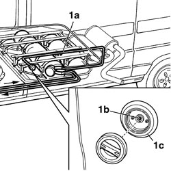
In the case of LPG system components maintenance or replacement operations that involve disconnecting the pipes, the section of the circuit involved must be bled following the instructions below.Take the vehicle outside the workshop to an open area and position at a minimum safety distance of 4 metres from other vehicles and from electrical systems and equipment.Wear the special helmet with visor and heavy-duty gloves illustrated previously that meet the UNI standards listed (see ASSEMBLY 10 index).Wait for the engine to cool down.1. In the case of operations to the components in section (1a) (from the filler to the tank) of the LPG circuit, drain the pipe by pressing at the single-acting valve (1b) on the LPG filler (1c).
Engines: 2.0 16V
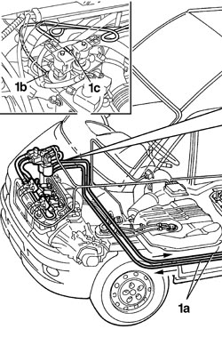
1. In the case of repairs to section (1a) (from the tank to the solenoid valve assembly / G4-G5) of the LPG circuit, drain the LPG in the supply and return pipes to the solenoid valve assembly / G4-G5 using the connectors (1b) and (1c).
Engines: 2.0 16V
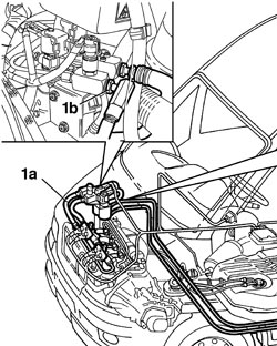
1. In the case of repairs to components in section (1a) (from the solenoid valve assembly / G4-G5 to the injectors) of the LPG circuit, drain the LPG in the supply pipe to the injectors via the connector (1b).
Engines: 2.0 16V
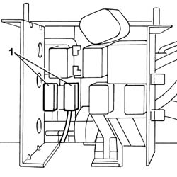
Once the section of pipe concerned has been drained, wait for at least 5 minutes before returning the vehicle to the workshop.1. Disconnect 5A fuse F01 and 15A fuse F03 protecting the solenoid valves and the LPG pump (taking great care over the original position) to prevent the engine from being started up in LPG mode with the consequent filling of the pipes.
Engines: 2.0 16V
Return the vehicle to the workshop (in petrol operating mode) and proceed with the necessary removal operations.