1004E20 ENGINE - DISMANTLE AND RE-BUILD FOLLOWING OPERATION 1004E10 - WASH AND CHECK DISMANTLED PARTS - RE-FIT CYLINDER HEAD AND OIL SUMP - DOES NOT INCLUDE REPAIRS TO CYLINDER HEAD AND AUXILIARY UNIT
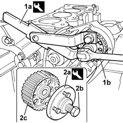
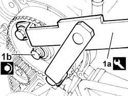
1. Use the tool (1a) with special adaptors and, using an ordinary spanner (1b), undo the nut fixing the pressure pump toothed drive pulley.
[symbol: 64_770]
Description
Code
Function
1a
Counter-torque
1.870.815.000
Timing pulley lock
[symbol: 64_770]
Description
Code
Function
1a
Pins for counter-torque
1.870.836.000
Timing pulley lock
2. Position the tool (2a), tighten the bolt (2b) and remove the pressure pump toothed drive pulley (2c).
[symbol: 64_770]
Description
Code
Function
2a
Extractor
1.870.855.000
Pressure pump control pulley removal
Engines: 2.3 JTD 16V
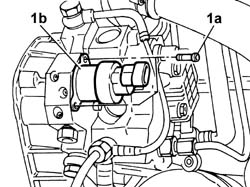
1. Undo the bolts (1a) and remove the pressure regulator (1b).
Engines: 2.3 JTD 16V
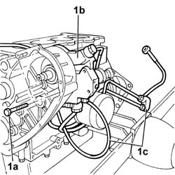
1. Undo the bolts (1a) and remove the pressure pump (1b) complete with fuel pipes and return manifold (1c).
Engines: 2.3 JTD 16V
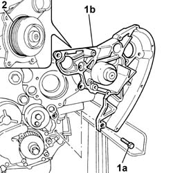
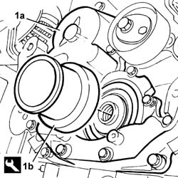
1. Undo the bolts (1a) and remove the support for the pressure pump (1b) with the water pump incorporated.2. Remove the seal from the water pump.
Engines: 2.3 JTD 16V
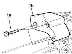
1. Undo the bolts (1a) and remove the rigid power unit support (1b).
Engines: 2.3 JTD 16V
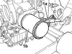
1. Using an ordinary tool (1a), undo the cartridge engine oil filter (1b) and remove it.
Engines: 2.3 JTD 16V
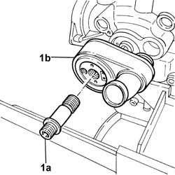
1. Undo the engine oil filter connector (1a) and remove the engine oil heat exchanger (1b).
Engines: 2.3 JTD 16V
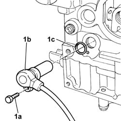
1. Undo the bolt (1a) and remove the rpm sensor (1b) and seal (1c).
Engines: 2.3 JTD 16V
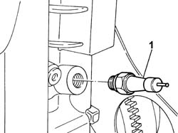
1. Undo and remove the engine oil pressure switch.
Engines: 2.3 JTD 16V
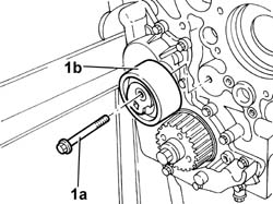
1. Undo the bolt (1a) and remove the automatic timing belt tensioner (1b).
Engines: 2.3 JTD 16V
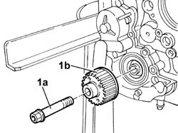
1. Undo the bolt (1a) and remove the timing belt toothed drive wheel (1b).
Engines: 2.3 JTD 16V
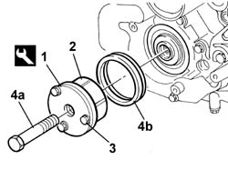
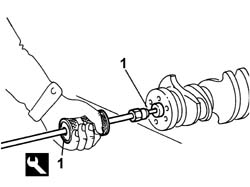
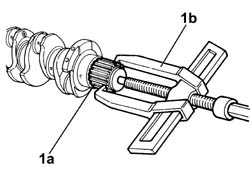
1. Use the tool described below to fit the oil sealing ring.2. Position the extraction jaws for the tool in the oil seal splining.3. Secure the extraction pincers in position using retaining bolts.4. Tighten the tool pin (4a) to remove the oil sealing ring(4b) from its seat.
[symbol: 64_770]
Description
Code
Function
1
Extractor
99340057
Extracting timig side crankshaft element
Engines: 2.3 JTD 16V
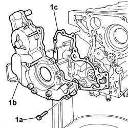
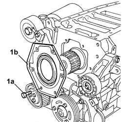
1. Undo the bolts (1a) and remove the crankshaft front cover (1b) with vacuum unit, oil pump and gasket (1c) incorporated.
Engines: 2.3 JTD 16V
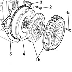
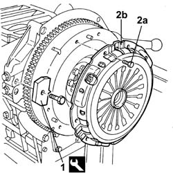
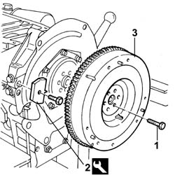
1. Undo the bolts (1a) and remove the clutch (1b).2. Undo the flywheel fixing bolts.3. Remove the tool.
[symbol: 64_770]
Description
Code
Function
3
Counter-torque
1.860.846.000
Flywheel lock
4. Remove the flywheel.5. Remove the protective cover.
Engines: 2.3 JTD 16V
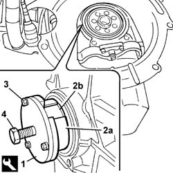
1. Use the tool described below to extract the flywheel side oil seal.2. Position the tool extraction pincers (2a) into oil sealing ring grooves (2b).3. Secure the extraction pincers in position using retaining bolts.4. Tighten the tool pin to remove the oil sealing ring from its seat.
[symbol: 64_770]
Description
Code
Function
1
Extractor
99340058
Extracting flywheel end crankshaft seal
Engines: 2.3 JTD 16V
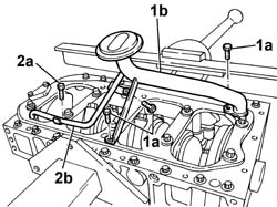
1. Undo the bolts (1a) and remove the oil intake duct (1b).2. Undo the bolt (2a) and remove the pipe (2b).
Engines: 2.3 JTD 16V
1. Fit the tool for rotating the engine.
[symbol: 64_770]
Description
Code
Function
1
Flange
1.860.815.000
Crankshaft rotation
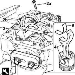
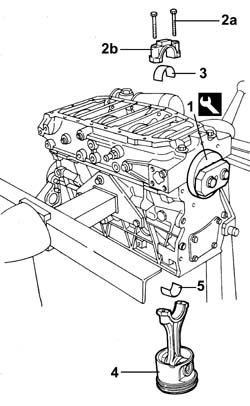
Rotate the crankshaft using the tool fitted previously until the piston concerned is at B.D.C.2. Undo the bolts (2a) and remove the connecting rod cap (2b).3. Remove the lower connecting rod half-bearing.4. Remove the connecting rod-piston assembly.5. Remove the upper connecting rod half-bearing.Carry out the same operations to remove the pistons and connecting rods for the remaining cylinders.Remove the tool.
[symbol: 64_770]
Description
Code
Function
.
Flange
1.860.815.000
Crankshaft rotation
Engines: 2.3 JTD 16V
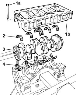
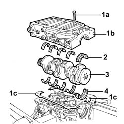
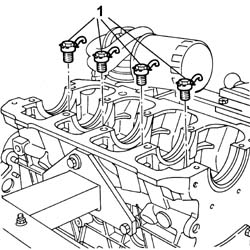
1. Undo the bolts (1a) and remove the lower crankcase (1b).2. Remove the lower main journal half-bearings.3. Remove the crankshaft.4. Remove the upper main journal half-bearings.
Engines: 2.3 JTD 16V
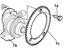
1. Undo the bolts (1a) and remove the flywheel (1c) from the crankshaft (1b).
Engines: 2.3 JTD 16V
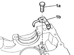
1. Undo the bolts (1a) and remove the piston lubrication jets (1b) from the crankcase.
Engines: 2.3 JTD 16V
Remove the cylinder head centering pins.Remove any damaged or broken studs.Drill and remove the water/oil sealing plugs from the crankcase to allow for washing.Undo the bolts and remove the crankcase from the mounting brackets, then place it on a special workbench.Characteristic of working principle
Wash the dismantled components.Fit the water/oil sealing plugs in the crankcase and tighten them to the recommended torque.
[symbol: 390_774]
Value daNm
Fastening
Component
Ø
.
2.5
Filler
ENGINE CRANKCASE
-
[symbol: 390_774]
Value daNm
Fastening
Component
Ø
.
1.7
Tapered plug
ENGINE CRANKCASE
3/8" X 10
[symbol: 390_774]
Value daNm
Fastening
Component
Ø
.
4.2
Male plug
ENGINE CRANKCASE
M14 X 1.5
[symbol: 390_774]
Value daNm
Fastening
Component
Ø
.
(Draining water) 2.0
Plug
ENGINE CRANKCASE
M14 X 1.5
[symbol: 390_774]
Value daNm
Fastening
Component
Ø
.
(Level sensor) 1.0
Plug
ENGINE CRANKCASE
M12 X 1.25
Lubricate all the mechanical components with engine oil.Check that the cylinder head support surface does not have cracks or superficial grooves.Check that the planarity of the cylinder head support surface corresponds to the recommended figure; if this is not the case, regrind the cylinder head support surface.
[symbol: 55_772]
Subject
Value
.
Crankcase and components
mm
-
Cylinder support surface flatness
< 0,10
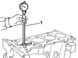
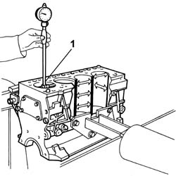
1. Measure the cylinder bore/liner diameter.
[symbol: 55_772]
Subject
Value
1
CRANKCASE AND COMPONENTS
mm
-
Cylinder liner bore
88.002 - 88.022
Check that the taper of the cylinder liners is within the recommended limits.
[symbol: 55_772]
Subject
Value
.
Crankcase and components
mm
-
Cylinder liner taper
< 0,05
Check that the ovality of the cylinder liners is within the recommended limits.
[symbol: 55_772]
Subject
Value
.
Crankcase and components
mm
-
Cylinder liner ovality
< 0,05
If the cylinder bore measurements are not within the recommended limits, ream the cylinder bores following the recommended oversizes.
Engines: 2.3 JTD 16V
Position the jets on the crankcase and secure them using the fixing bolts.Check that there are no deposits or blockages in the crankshaft lubrication ducts.Check the static balance of the crankshaft resting the main journals on suitable parallels.Check that the diameter of the main journals is within specified limits.
[symbol: 55_772]
Subject
Value
.
CRANKSHAFT
mm
-
Main journal diameter
71.182 - 71.202
-(76.182 - 76.208*)
-
If the diameter of the main journals is not correct, they should be reground to the recommended undersize.
[symbol: 55_772]
Subject
Value
.
Crankshaft
mm
-
Main journal undersize
0,254 - 0,508
The undersize should be marked by a special stamp on the side of the no. 1 crank arm.For undersize main journals: the letter M.For undersize main journals and crankpins: the letters MB.Check that the diameter of the crankpins corresponds to the recommended figures.
[symbol: 55_772]
Subject
Value
.
CRANKSHAFT
mm
-
Crankpin diameter
59.015 - 59.038
If the diameter of the crankpins is not correct, they should be reground to the recommended undersize.
[symbol: 55_772]
Subject
Value
.
Crankshaft
mm
-
Crankpin undersize
0,254 - 0,508
The undersize should be marked by a special stamp on the side of the no. 1 crank arm.For undersize crankpins: the letter B.For undersize main journals and crankpins: the letters MB.
[symbol: 55_772]
Subject
Value
.
Crankshaft
mm
-
Ovality
0,005
-
Taper
0,005
[symbol: 55_772]
Subject
Value
.
Crankshaft
mm
-
Main journal misalignment
0,05
-
Crankpin misalignment
0,125
Regrind the shaft following the recommended figures.Check that the thickness of the half-bearings corresponds to the recommended figures; if not, replace them.
[symbol: 55_772]
Subject
Value
.
MAIN BEARINGS
-
Main bearing half thickness
mm
-
Category A
2.155 - 2.164
-
Category B
2.165 - 2.174
[symbol: 55_772]
Subject
Value
.
MAIN BEARINGS
-
Main bearing half thickness
mm
-
Category C
2.175 - 2.184
-
Category D
2.185 - 2.194
Check that the thickness of the connecting rod half-bearings is within specified limits; if not, replace them.
[symbol: 55_772]
Subject
Value
.
BIG END BEARINGS
-
Connecting rod side big end half-bearing size
mm
-
Category A
1.875 - 1.884
-
Category B
1.883 - 1.892
[symbol: 55_772]
Subject
Value
.
BIG END BEARINGS
-
Connecting rod side big end half-bearing size
mm
-
Category C
1.891 - 1.900
[symbol: 55_772]
Subject
Value
.
BIG END BEARINGS
-
Cap side big end half-bearing size
mm
-
Category A
1.877 - 1.883
-
Category B
1.885 - 1.891
[symbol: 55_772]
Subject
Value
.
BIG END BEARINGS
-
Cap side big end half-bearing size
mm
-
Category C
1.893 - 1.899
Position the flywheel on the crankshaft and secure it by tightening the fixing bolts to the recommended torque.
[symbol: 390_774]
Value daNm
Fastening
Component
Ø
.
1.5
Bolt
PHONIC WHEEL ON CRANKSHAFT
M6 X 1
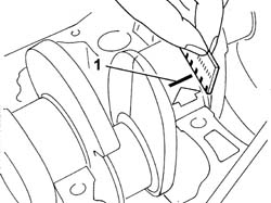
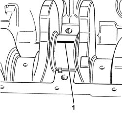
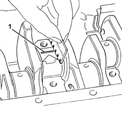
Fit the upper main journal half-bearings in the cylinder block/crankcase.Fit the crankshaft in the crankcase.1. Fit the calibrated wire (plastigate) for measuring the bearing clearance.
Engines: 2.3 JTD 16V
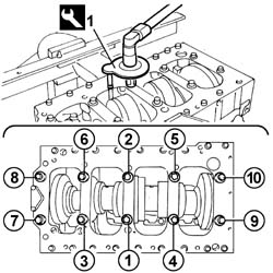
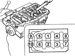
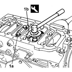
Position the gaskets and the lower main journal half-bearings on the lower crankcase.Fit the lower crankcase.1. Using the special tool and a torque wrench, tighten the lower crankcase fixing bolts to the recommended torque in the order given.
[symbol: 64_770]
Description
Code
Function
1
Torque wrench
1.860.942.000
Angular tightening of lower crankcase bolts
[symbol: 390_774]
Value daNm
Fastening
Component
Ø
1
(Inner side) 5 + 60° + 60°
Bolt
ENGINE CRANKCASE
-
[symbol: 390_774]
Value daNm
Fastening
Component
Ø
1
(Outer side) 3
Bolt
ENGINE CRANKCASE
-
Engines: 2.3 JTD 16V
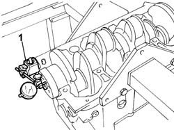
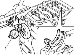
1. Check that the crankshaft endfloat corresponds to the recommended figures using a magnetic base and dial gauge.
[symbol: 55_772]
Subject
Value
.
CRANKSHAFT
mm
-
End float
0.010 - 0.240
Engines: 2.3 JTD 16V
If the crankshaft endfloat does not correspond to the recommended figure, the crankshaft must be reground and the crankshaft half-bearings replaced as a result.1. Remove the lower crankcase and the half-bearings and measure the bearing clearance using the special gauge.
[symbol: 55_772]
Subject
Value
.
MAIN BEARINGS
mm
-
Radial clearance
0.044 - 0.075
Engines: 2.3 JTD 16V
Check that the internal diameter of the piston bushes is within the recommended limits; if not, replace the piston.
[symbol: 55_772]
Subject
Value
.
PISTON SET
mm
-
Piston bush internal diameter
31.003 - 31.009
Check that the outer diameter of the gudgeon pins is within the recommended limits; if not, replace the gudgeon pins.
[symbol: 55_772]
Subject
Value
.
GUDGEON PIN
mm
-
Outer diameter
30.990 - 30,996
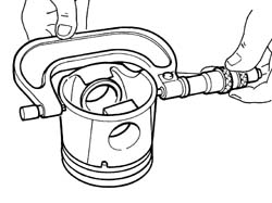
Check that the outer diameter of the pistons corresponds to the recommended figures; if not, replace the piston complete with piston rings and gudgeon pin.
[symbol: 55_772]
Subject
Value
.
PISTON SET
mm
-
Outer diameter
87.903 - 87.937
Engines: 2.3 JTD 16V
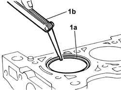
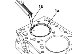
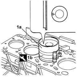
1. If the bore has to be reamed, fit the piston rings (1a) and the oil scraper ring in the cylinder bore and using a feeler gauge (1b) check that the gap between the end of each ring corresponds to the recommended figures; if not, replace the piston rings.
[symbol: 55_772]
Subject
Value
1
PISTON RING SET
mm
-
First ring gap
0.200 - 0.350
-
Second ring gap
0.600 - 0.800
-
Oil scraper ring gap
0.250 - 0.500
Engines: 2.3 JTD 16V
Check that the thickness of the piston rings and the oil scraper ring is within the recommended limits.
[symbol: 55_772]
Subject
Value
PISTON RING SET
mm
-
First ring size
2.068 - 2.097 (*)
-
Second ring size
1.970 - 1.990
-
Oil scraper ring size
2.470 - 2.490
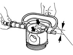
Check that the axial clearance between each ring and the housing in the piston corresponds to the recommeded figures.
[symbol: 55_772]
Subject
Value
1a
PISTON RING SET
mm
-
First ring end float
-
-
Second ring clearance
0.015 - 0.037
-
Oil scraper ring clearance
0.050 - 0.090
Characteristic of working principle Fit the crankcase on the overhaul stand and secure it using the bolts.Fit the upper main journal half-bearings in the cylinder block/crankcase.Fit the crankshaft in the crankcase.1. Position a bead of sealant about 1.5 mm thick on the crankcase.
[symbol: 14_773]
Description
Q.ty
Component
Type
Classification
1
LOCTITE 5205
-
ENGINE CRANKCASE
Sealant
-
Engines: 2.3 JTD 16V
Fit the lower crankcase.Tighten the bolts fixing the lower crankcase to torque in the order given.
[symbol: 390_774]
Value daNm
Fastening
Component
Ø
1
(Inner side) 5 + 60° + 60°
Bolt
ENGINE CRANKCASE
-
[symbol: 390_774]
Value daNm
Fastening
Component
Ø
1
(Outer side) 3
Bolt
ENGINE CRANKCASE
-
Fit the tool for rotating the crankshaft.
[symbol: 64_770]
Description
Code
Function
.
Flange
1.860.815.000
Crankshaft rotation
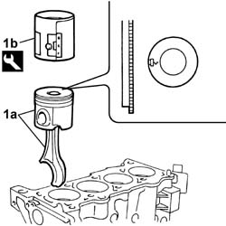
Rotate the crankcase through 90° on the overhaul stand.Rotate the crankshaft until the cylinder concerned is at B.D.C.1. Fit the piston-connecting rod assembly (1a) complete with half-bearing using the tool (1b).
[symbol: 64_770]
Description
Code
Function
.
Fitting tool
1.860.700.000
Fitting tool
Engines: 2.3 JTD 16V
Rotate the crankcase through 90° on the overhaul stand.Fit the connecting rod cap complete with half-bearing and secure it without tightening the bolts.Proceed in the same way for the remaining pistons and connecting rods.Tighten the connecting rod cap bolts to the recommended torque using the angular tightening tool.
[symbol: 390_774]
Value daNm
Fastening
Component
Ø
.
4 + 60°
Bolt
CONNECTING ROD CAP FASTENERS
-
[symbol: 64_770]
Description
Code
Function
1
Torque wrench
1.860.942.000
Connecting rod cap bolt angular tightening
Position the engine oil intake and the pipe and secure them using the bolts.
[symbol: 390_774]
Value daNm
Fastening
Component
Ø
.
1.0
Bolt
OIL SECTION PUMP
M6 X 1
Position the oil sump with the gasket and ring gear and secure it tightening the bolts to the recommended torque.
[symbol: 390_774]
Value daNm
Fastening
Component
Ø
.
2.5
Bolt
ENGINE OIL SUMP
M8 X 1.25
[symbol: 390_774]
Value daNm
Fastening
Component
Ø
.
1.0
Bolt
ENGINE OIL SUMP
M6 X 1
Fit a new front crankshaft cover gasket.Position the crankshaft front cover with the vacuum unit and oil pump incorporated and screw in the fixing bolts without tightening them.1. Centre the crankshaft front cover with the vacuum unit and oil pump (1a) incorporated using the tool (1b).
[symbol: 64_770]
Description
Code
Function
1b
Locator
99396037
Tool for locating front crankshaft cover
Engines: 2.3 JTD 16V
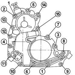
1. Tighten the crankshaft front cover fixing bolts in the order given.
[symbol: 390_774]
Value daNm
Fastening
Component
Ø
.
1.0
Bolt
ENGINE OIL PUMP
M6 X 1
Engines: 2.3 JTD 16V
1. Use the tool described below to fit the timing side oil seal.
[symbol: 64_770]
Description
Code
Function
1
Fitting tool
99346254
Front cover gasket fitting
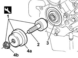
2. Tighten the threaded tool pin until it comes into contact with the crankshaft drive gear seat.3. Position a new oil seal in its seat.4. Position the fitting tool (4a) in contact with the oil sealing ring and tighten the nut (4b) to fully fit the oil sealing ring into its seat on the front cover.
Engines: 2.3 JTD 16V
Position the rigid power unit support and tighten the fixing bolts to the recommended torque.
[symbol: 390_774]
Value daNm
Fastening
Component
Ø
.
5
Bolt
RIGID ENGINE MOUNT, TIMING SIDE
M10X1.5
Position the water pump with a new seal.Tighten the fixing bolts to the recommended torque.
[symbol: 390_774]
Value daNm
Fastening
Component
Ø
.
2.5
Bolt
COOLANT PUMP
M8 X 1.25
[symbol: 390_774]
Value daNm
Fastening
Component
Ø
.
1.0
Bolt
COOLANT PUMP
M6 X 1
Position the engine coolant inlet pipe and tighten the bolt fixing it ot the crankcase.Position the engine oil heat exchanger with a new gasket and tighten the engine oil filter connector to the recommended torque.
[symbol: 390_774]
Value daNm
Fastening
Component
Ø
.
8.0
Connector
ENGINE OIL HEAT EXCHANGER
M22 X 1.5
Position the engine oil filter and tighten it by hand to the torque given in the table.
[symbol: 390_774]
Value daNm
Fastening
Component
Ø
.
2.5
-
CARTRIDGE OIL FILTER
M22 X 1.5
Position the rpm sensor with a new seal and secure it using the special bolt.Position the pressure pump complete with fuel pipes and secure it tightening the special bolt to the recommended torque.
[symbol: 390_774]
Value daNm
Fastening
Component
Ø
.
2.5
Bolt
INJECTION PUMP TIMING
M8 X 1.25
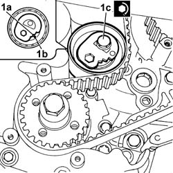
Position the pressure regulator and tighten the fixing bolts.Position the pressure pump toothed drive pulley.1. Use the tool (1a) with special adaptors and, using an ordinary spanner (1b), tighten the nut fixing the pressure pump toothed drive pulley (1c) to the recommended torque.
[symbol: 64_770]
Description
Code
Function
1a
Counter-torque
1.870.815.000
Timing pulley lock
[symbol: 64_770]
Description
Code
Function
1a
Pins for counter-torque
1.870.836.000
Timing pulley lock
[symbol: 390_774]
Value daNm
Fastening
Component
Ø
.
7.0
Nut
PRESSURE PUMP CONTROL PULLEY
M14 X 1.5
Engines: 2.3 JTD 16V
Remove the tool.
[symbol: 64_770]
Description
Code
Function
.
Flange
1.860.815.000
Crankshaft rotation
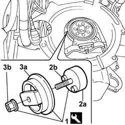
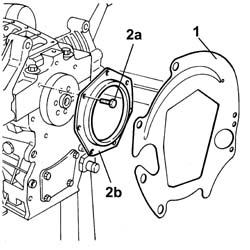
Tilt the engine 90° on the overhaul stand.Fit the protective cover.1. Use the tool described below to fit the flywheel side oil seal.2. Apply plate (2a) to the crankshaft and secure using retaining bolts (2b).Position a new oil seal in its seat.3. Position the fitting tool (3) in contact with the oil sealing ring and tighten the nut (3b) to fully fit the oil seal into its seat on the crankshaft.
[symbol: 64_770]
Description
Code
Function
1
Fitting tool
99346255
Flywheel end crankshaft seal fitting
Engines: 2.3 JTD 16V
Position the flywheel and secure it tightening the bolts to the recommended torque.
[symbol: 390_774]
Value daNm
Fastening
Component
Ø
.
3.0
Bolt
FLYWHEEL (MECH.)
M12 X 1.25
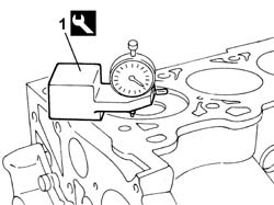
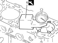
Return the engine to its original position.1. Rotate the crankshaft and measure the projection of the pistons at two points 180° on the gudgeon pin axis using the tool.
[symbol: 64_770]
Description
Code
Function
1
Dial gauge support
1.870.404.000
Piston projection from cylinder head support plane check
[symbol: 55_772]
Subject
Value
.
ENGINE PISTON
mm
-
Piston projection
0.300-0,600
Engines: 2.3 JTD 16V
Measure the piston projection or recess.
[symbol: 55_772]
Subject
Value
.
CYLINDER HEAD GASKET
mm
-
Size
1.100
-
Maximum piston projection
0.300 - 0.400
[symbol: 55_772]
Subject
Value
.
CYLINDER HEAD GASKET
mm
-
Size
1.200
-
Maximum piston projection
0.400 - 0.500
[symbol: 55_772]
Subject
Value
.
CYLINDER HEAD GASKET
mm
-
Size
1.300
-
Maximum piston projection
0.500 - 0.600
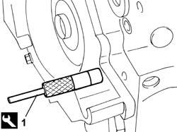
Position the first and fourth pistons close to T.D.C.1. Undo the plug in the crankcase and, rotating the crankshaft using small movements, position the tool for detecting T.D.C. in the housing for the plug.
[symbol: 64_770]
Description
Code
Function
1
Pin
99360615
TDC positioning
Engines: 2.3 JTD 16V
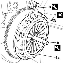
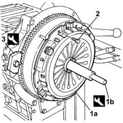
1. Fit the clutch (1a) using the tool (1b).
[symbol: 64_770]
Description
Code
Function
1b
Clutch locating tool
1.875.029.000
Driven plate locating
2. Tighten the fixing bolts to the recommended torque.
[symbol: 390_774]
Value daNm
Fastening
Component
Ø
2
2.7
Bolt
CLUTCH ASSEMBLY
M8 X 1.25
3. Fit the tool.
[symbol: 64_770]
Description
Code
Function
3
Counter-torque
1.860.846.000
Flywheel lock
Engines: 2.3 JTD 16V
Fit the toothed drive pulley and tighten the fixing bolt to the recommended torque.
[symbol: 390_774]
Value daNm
Fastening
Component
Ø
.
35
Bolt
ENGINE ASSEMBLY
M18 X 1.5
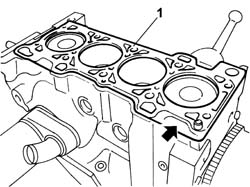
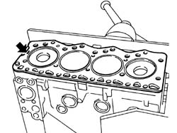
Position the cylinder head locating bushes on the engine block.1. Fit the cylinder head gasket with the word "ALTO" facing the flywheel side.
Engines: 2.3 JTD 16V
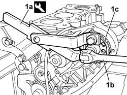
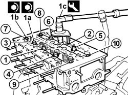
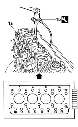
Position the cylinder head on the cylinder block/crankcase.1. Tighten the centre fixing bolts (1a) and the side fixing bolts (1b) to the recommended torque using the angular tightening tool (1c).
[symbol: 390_774]
Value daNm
Fastening
Component
Ø
1a
(Centre fastening) 10 + 90° + 90°
Bolt
CYLINDER HEAD
-
[symbol: 390_774]
Value daNm
Fastening
Component
Ø
1b
(Side fastening) 5 +60° +60°
Bolt
CYLINDER HEAD
-
[symbol: 64_770]
Description
Code
Function
1c
Torque wrench
1.860.942.000
Tightening cylinder head bolts to cylinder block
Engines: 2.3 JTD 16V
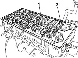
1. Position the tappets and the rocker arms in their housings.Position the camshaft housing locating dowels.2. Position the upper cylinder head gasket on the locating dowels.
Engines: 2.3 JTD 16V
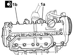
1. Position the camshaft housing (1a) on the cylinder head and tighten the bolts (1b) to the recommended torque.
[symbol: 390_774]
Value daNm
Fastening
Component
Ø
1b
11,5
Bolt
CYLINDER HEAD EXTENSION
M12X1.25
Engines: 2.3 JTD 16V
Fit the fixed timing belt tensioner and tighten the retaining bolt to the recommended torque.
[symbol: 390_774]
Value daNm
Fastening
Component
Ø
.
2.5
Bolt
FIXED TENSIONER
M8 X 1.25
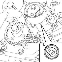
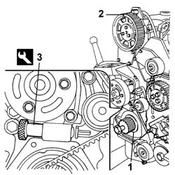
Fit the moving timing belt tensioner and screw in the retaining bolt without tightening it.1. Rotate the moving tensioner to the position illustrated to facilitate the fitting of the timing belt.
Engines: 2.3 JTD 16V
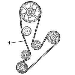
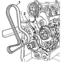
1. Fit the timing belt onto the pulleys and gears.
Engines: 2.3 JTD 16V
Remove the timing pin for the timing pulley in relation to the timing sensor.
[symbol: 64_770]
Description
Code
Function
.
Pin for timing adjustment
1.860.617.000
Positioning of timing pulley with timing sensor
1. Using the reaction tool (1a) fitted with pins, tighten the bolt fixing the timing drive pulley (1b) to torque.
[symbol: 64_770]
Description
Code
Function
1a
Counter-torque
1.870.815.000
Timing pulley lock
[symbol: 64_770]
Description
Code
Function
1a
Pins for counter-torque
1.870.836.000
Timing pulley lock
Engines: 2.3 JTD 16V
1. Acting on the hexagonal bolt (1a), rotate the semi-automatic tensioner in an anti-clockwise direction, placing the tensioner (1b) moving reference in the position illustrated, i.e. about 20°-22° to the right of the position indicated by the reference (1c), then lock the fixing nut (1d).
Engines: 2.3 JTD 16V
Tighten the bolt fixing the automatic tensioner.Remove the tools used for timing the camshafts and for positioning the crankshaft close to T.D.C.
[symbol: 64_770]
Description
Code
Function
.
Templates
99360614
Camshaft timing adjustment
[symbol: 64_770]
Description
Code
Function
.
Pin
99360615
TDC positioning
Rotate the crankshaft through eight revolutions in its direction of rotation.1. Loosen the bolt fixing the tensioner and, working carefully, position the tensioner (1a) reference in line with the reference opening (1b), then tighten the nut (1c) fixing the belt tensioner to torque.
[symbol: 390_774]
Value daNm
Fastening
Component
Ø
1c
3.6
Bolt
MOBILE TIMING TENSIONER
M8
Engines: 2.3 JTD 16V
Rotate the crankshaft through two further revolutions in its direction of rotation.Check that the position of the references remains unchanged, then temporarily refit the tools for timing the camshafts and the crankshaft for a final check.If the tools do not fit perfectly in the housings or the references on the tensioner have moved, carry out the belt tension adjustment procedure again.Fit the studs on the camshaft housing for the timing tools.Fit the mounting bracket on the camshaft housing and tighten the fixing bolt and nut.Fit the thermostat and tighten the fixing bolts.Position the oil dipstick pipe.Position the intake manifold and tighten the fixing bolts to the recommended torque.
[symbol: 390_774]
Value daNm
Fastening
Component
Ø
.
2.5
Bolt
INLET MANIFOLD
M8 X 1.25
Tighten the heater plugs.Position the injectors and the seals and tighten the fixing bolts to the recommended torque.
[symbol: 390_774]
Value daNm
Fastening
Component
Ø
.
2.5
Bolt
INJECTORS(DIESEL)
M8 X 1.25
Position the fuel manifold and tighten the fixing bolts to the recommended torque.
[symbol: 390_774]
Value daNm
Fastening
Component
Ø
.
2.5
Bolt
INJECTOR FUEL MANIFOLD (DIESEL)
M8 X 1.25
Position the pipes from the fuel manifold to the injectors and tighten the connectors to the recommended torque.
[symbol: 390_774]
Value daNm
Fastening
Component
Ø
.
2.3
Connector
PIPE FUEL MANIFOLD TO INJECTORS
M12 X 1.5
Position the pipe from the fuel manifold to the pressure pump and tighten the connectors to the recommended torque.
[symbol: 390_774]
Value daNm
Fastening
Component
Ø
.
2.3
Connector
PRESSURE PUMP LINE TO FUEL MANIFOLD
M14X1.5
Position the fuel return pipe connector and tighten it to the recommended torque.
[symbol: 390_774]
Value daNm
Fastening
Component
Ø
.
4
Connector
INJECTOR FUEL MANIFOLD (DIESEL)
M16
Position the fuel return pipe from the injectors and secure it using the special springs.Position the engine oil pressure sensor and tighten it.Position the pipe from the thermostat to the radiator and the pipe from the engine oil heat exchanger to the radiator and secure them using the bolts and the retaining bands.Position the timing sensor in its housing and secure it using the bolts.Position the oil vapour separator and tighten the fixing bolts to the recommended torque.
[symbol: 390_774]
Value daNm
Fastening
Component
Ø
.
1.0
Bolt
ENGINE OIL VAPOUR SEPARATOR
M6 X 1
Position the timing cover and tighten the fixing bolts to the recommended torque.
[symbol: 390_774]
Value daNm
Fastening
Component
Ø
.
1.0
Bolt
TIMING BELT PROTECTIVE COVER(S)
M6 X 1
Position the crankshaft pulley and tighten the fixing bolts to the recommended torque.Position the injection wiring and the heater plugs wiring.Connect the heater plug connections.
[symbol: 394_771]
Description
Connector
.
Heater plugs
A040A
[symbol: 394_771]
Description
Connector
.
Heater plugs
A040B
[symbol: 394_771]
Description
Connector
.
Heater plugs
A040C
[symbol: 394_771]
Description
Connector
.
Heater plugs
A040D
Connect the electrical connections for the injection wiring.
[symbol: 394_771]
Description
Connector
.
Injector
N070A
[symbol: 394_771]
Description
Connector
.
Injector
N070B
[symbol: 394_771]
Description
Connector
.
Injector
N070C
[symbol: 394_771]
Description
Connector
.
Fuel pressure sensor
K083
[symbol: 394_771]
Description
Connector
.
Timing sensor
K047
[symbol: 394_771]
Description
Connector
.
Injector
N070D
[symbol: 394_771]
Description
Connector
.
Coolant temperature sending unit (for instrument panel)
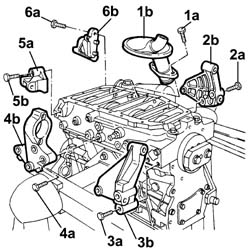
1. Undo the bolts (1a) and remove the engine oil intake duct (1b) releasing it from its housing.2. Undo the fixing bolts (2a) and remove the front manifold side bracket (2b).3. Undo the fixing bolts (3a) and remove the pressure pump side front bracket (3b) complete with engine rpm sensor.4. Undo the fixing bolts (4a) and remove the intermediate driveshaft mounting bracket (4b).5. Undo the fixing bolts (5a) and remove the pressure pump side rear bracket (5b).6. Undo the fixing bolts (6a) and remove the rear manifold side bracket (6b).
Rotate the crankshaft using the tool fitted previously until the cylinder concerned is at B.D.C.2. Undo the bolts (2a) and remove the connecting rod cap (2b).3. Remove the lower connecting rod half-bearing.4. Remove the connecting rod-piston assembly.5. Remove the upper connecting rod half-bearing.Carry out the same operations to remove the pistons and connecting rods for the remaining cylinders.Remove the tool.
1. Undo the bolts (1a) and remove the lower crankcase (1b) and the gasket (1c).2. Remove the lower main journal half-bearings.3. Remove the crankshaft.4. Remove the upper main journal half-bearings.
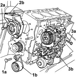
Rotate the crankcase through 180° on the overhaul stand.1. Undo the bolts (1a) and remove the fixed timing belt tensioner (1b).2. Undo the bolts (2a) and remove the front engine support complete with water pump (2b).3. Undo the bolts (3a) and remove the auxiliary unit (3b).
Remove the cylinder head centering pins.Remove any damaged or broken studs.Drill and remove the water/oil sealing plugs from the crankcase to allow for washing.Undo the bolts and remove the crankcase from the mounting brackets, then place it on a special workbench.Characteristic of working principle Proceed with the reassembly.Wash the dismantled components.Fit the water/oil sealing plugs in the crankcase using suitable fitting tools.Lubricate all the mechanical components with engine oil.Check that the cylinder head support surface does not have cracks or superficial grooves.Check that the planarity of the cylinder head support surface corresponds to the recommended figure; if this is not the case, regrind the cylinder head support surface.
[symbol: 55_772]
Subject
Value
.
Crankcase and components
mm
-
Cylinder support surface flatness
< 0,10
1. Measure the cylinder bore/liner diameter.
[symbol: 55_772]
Subject
Value
1
Cylinder liner bore
mm
-
Category A
94,402 - 94,412
-
Category B
94,413 - 94,422
-
Category C,
94,423 - 94,432
Check that the taper of the cylinder liners is within the recommended limits.
[symbol: 55_772]
Subject
Value
.
Crankcase and components
mm
-
Cylinder liner taper
< 0,05
Check that the ovality of the cylinder liners is within the recommended limits.
[symbol: 55_772]
Subject
Value
.
Crankcase and components
mm
-
Cylinder liner ovality
< 0,05
If the cylinder bore measurements are not within the recommended limits, ream the cylinder bores following the recommended oversizes.
Check that there are no deposits or blockages in the crankshaft lubrication ducts.Check the static balance of the crankshaft resting the main journals on suitable parallels.Check that the diameter of the main journals is within specified limits.
[symbol: 55_772]
Subject
Value
.
Crankshaft
mm
-
Main journal diameter
80,182 - 80,208
-
Main journal diameter
86,182- 86,208 (*)
(*) main journal n°5If the diameter of the main journals is not correct, they should be reground to the recommended undersize.
[symbol: 55_772]
Subject
Value
.
Crankshaft
mm
-
Main journal undersize
0,254 - 0,508
Check that the diameter of the crankpins corresponds to the recommended figures.
[symbol: 55_772]
Subject
Value
.
Crankshaft
mm
-
Crankpin diameter
56,515 - 56,538
If the diameter of the crankpins is not correct, they should be reground to the recommended undersize.
[symbol: 55_772]
Subject
Value
.
Crankshaft
mm
-
Main journal undersize
0,254 - 0,508
[symbol: 55_772]
Subject
Value
.
Crankshaft
mm
-
Ovality
0,005
-
Taper
0,005
[symbol: 55_772]
Subject
Value
.
Crankshaft
mm
-
Main journal misalignment
0,05
-
Crankpin misalignment
0,125
1. Regrind the shaft following the recommended figures.Check that the thickness of the half-bearings corresponds to the recommended figures; if not, replace them.
[symbol: 55_772]
Subject
Value
.
Main bearing half thickness
mm
-
Category A
2,165 - 2,174
-
Category B
2,319 - 2,428
-
Category C
2,573 - 2,682
Check that the thickness of the connecting rod half-bearings is within specified limits; if not, replace them.
[symbol: 55_772]
Subject
Value
.
Connecting rod bearing half thickness
mm
-
Category A
1,875 - 1,884
-
Category B
2,129 - 2,138
-
Category C
2,483 - 2,492
Fit the upper main journal half-bearings in the cylinder block/crankcase.Fit the crankshaft in the crankcase1. Fit the calibrated wire (plastigate) for measuring the bearing clearance.
Position the gaskets and the lower main journal half-bearings on the lower crankcase.Fit the lower crankcase.1. Tighten the bolts fixing the lower crankcase to the recommended torque in the order given.
If the crankshaft endfloat does not correspond to the recommended figure, the crankshaft must be reground and the crankshaft half-bearings replaced as a result.1. Remove the lower crankcase and the half-bearings and measure the bearing clearance using the special gauge.
1. If the bore has to be reamed, fit the piston rings (1a) and the oil scraper ring in the cylinder bore and check that the gap (1b) between the end of each ring corresponds to the recommended figures; if not, replace the piston rings.
Check that the thickness of the piston rings and the oil scraper ring is within the recommended limits.
[symbol: 55_772]
Subject
Value
.
Piston ring set
mm
-
First ring size
2,068 - 2,097 (*)
-
Second ring size
1,970 - 1,995
-
Oil scraper ring size
2.470 - 2.490, mm
(*) measured at the 91.4 mm diameter1. Check that the axial clearance (1a) between each ring (1b) and the housing in the piston (1c) corresponds to the recommeded figure.
Characteristic of working principle Fit the crankcase on the overhaul stand and secure it using the bolts.Fit the upper main journal half-bearings in the cylinder block/crankcase.Fit the crankshaft in the crankcase.Position the gaskets and the lower main journal half-bearings on the lower crankcase.Fit the lower crankcase.Tighten the bolts fixing the lower crankcase to the recommended torque in the order given.
[symbol: 390_774]
Value daNm
Fastening
Component
Ø
.
(engine crankcase side) 4.5 -5.5
Bolt
LOWER CRANKCASE
M14
1. Fit the tool.
[symbol: 64_770]
Description
Code
Function
1
Flange
1.860.815.000
Crankshaft rotation
Rotate the crankcase through 90° on the overhaul stand.Rotate the crankshaft until the cylinder concerned is at B.D.C.1. Fit the piston-connecting rod assembly (1a) complete with half-bearing using the tool (1b).
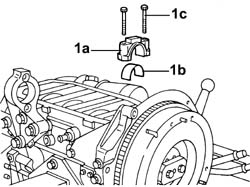
Rotate the crankcase through 90° on the overhaul stand.1. Fit the connecting rod cap (1a) complete with half-bearing (1b) and secure it without tightening the bolts (1c).Carry out the same operations to refit the pistons and connecting rods for the remaining cylinders.
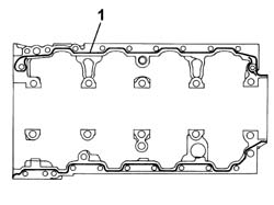
Fit the engine oil intake and tighten the fixing bolts.Fit the brackets on the lower crankcase securing them using the bolts.Apply sealant to the entire perimeter of the crankcase sump.
[symbol: 14_773]
Description
Q.ty
Component
Type
Classification
.
Dow Corning 7091
-
ENGINE OIL SUMP
Silicon sealant
-
Fit the crankcase sump.Tighten the bolts securing the crankcase sump to the recommended torque.
[symbol: 390_774]
Value daNm
Fastening
Component
Ø
.
1,8
Bolt
ENGINE OIL SUMP
M8
Fit the auxiliary unit and screw in the bolts without tightening them to torque.Fit the front engine support complete with water pump after having applied the sealant and tighten the bolts to the recommended torque.
[symbol: 390_774]
Value daNm
Fastening
Component
Ø
.
(injector side) 5.0
Bolt
COOLANT PUMP
M10
[symbol: 14_773]
Description
Q.ty
Component
Type
Classification
.
Dow Corning 7091
-
COOLANT PUMP
Silicon sealant
-
Fit the lower fixed tensioner and secure it tightening the fixing bolt to the recommended torque.
[symbol: 390_774]
Value daNm
Fastening
Component
Ø
.
2.5
Bolt
FIXED TENSIONER
M8
Fit the guard and the upper fixed tensioner tightening the fixing bolts to the recommended torque.
[symbol: 390_774]
Value daNm
Fastening
Component
Ø
.
2.5
Bolt
FIXED TENSIONER
M8
1. Measure the piston projection in two places at 180° on the gudgeon pin axis using the tool and take the average of the two values measured for each piston.
[symbol: 64_770]
Description
Code
Function
1
Dial gauge support
1.870.404.000
Piston projection from cylinder head support plane check
Position the cylinder head on the cylinder block/crankcase.1. Tighten the cylinder head bolts (1a) to the recommended torque using the angular tightening tool (1b).
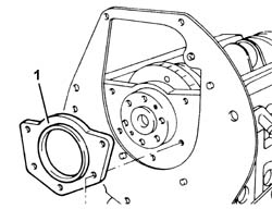
Fit the protective cover.Fit the crankcase rear cover with the oil seal incorporated and tighten the fixing bolts to the recommended torque.
[symbol: 390_774]
Value daNm
Fastening
Component
Ø
.
(engine crankcase side) 2.5
Bolt
REAR COVER CRANKSHAFT
M8
1. Fit the tool.
[symbol: 64_770]
Description
Code
Function
1
Counter-torque
1.860.741.000
Tool for preventing crankshaft rotation
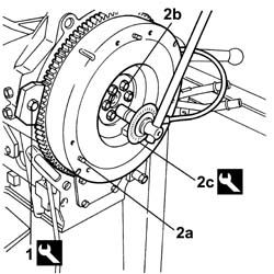
2. Fit the flywheel (2a), apply thread-locking agent to the bolts (2b) and tighten them to the recommended torque using the angular tightening tool (2c).
Fit the crankcase front cover with the oil seal incorporated and tighten the fixing bolts to the recommended torque.
[symbol: 390_774]
Value daNm
Fastening
Component
Ø
.
(engine crankcase side) 2.3
Bolt
FRONT COVER CRANKSHAFT
M8
Rotate the engine through 180° on the overhaul stand.1. Check that the reference on the timing gear is in a vertical position.2. Check that the camshaft references are aligned.3. Fit the tool.
1. Fully fit the toothed timing drive belt.Remove the tool.
[symbol: 64_770]
Description
Code
Function
.
Calibrated shim
1.860.638.000
Timing belt tensioning
Rotate the crankshaft through two revolutions.Check once again that the timing references on the crankshaft and the camshaft are aligned.2. Tighten the belt tensioner nut to the recommended torque.
Fit the timing belt covers and secure them using the bolts.Fit the oil filler plug.Fit the tool.
[symbol: 64_770]
Description
Code
Function
.
Counter-torque
1.860.741.000
Tool for preventing crankshaft rotation
Fit the crankshaft pulley and tighten the bolt to the recommended torque.
[symbol: 390_774]
Value daNm
Fastening
Component
Ø
.
(crankshaft side) 20
Bolt
CRANKSHAFT PULLEY
M20
Remove the tool.
[symbol: 64_770]
Description
Code
Function
.
Counter-torque
1.860.741.000
Tool for preventing crankshaft rotation
Fit the camshaft cover and the gasket underneath and tighten the fixing bolts to the recommended torque.
[symbol: 390_774]
Value daNm
Fastening
Component
Ø
.
1,0
Bolt
CAM COVER
M6
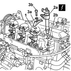
1. Fit the injector bracket support pads.2. Fit the injectors (2a) complete with gasket (2b).3. Fit the injector brackets (3a) and tighten the bolts (3b) to the recommended torque.
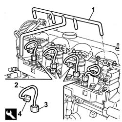
1. Position the connectors for the pipe from the injectors to the fuel recovery manifold in the injector housings and connect the pipe to the fuel manifold.2. Fit the pipes from the fuel manifold to the injectors.3. Tighten the connectors for the pipes from the fuel manifold to the manifold side injectors to the recommended torque.
[symbol: 390_774]
Value daNm
Fastening
Component
Ø
3
(Manifold end) 2.6 - 3.2
Connector
PIPE FUEL MANIFOLD TO INJECTORS
M14
4. Tighten the connectors for the pipes from the fuel manifold to the injector side injectors to the recommended torque.
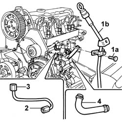
1. Fit the oil dipstick assembly and secure it using the bolt.2. Place the pipe from the pressure pump to the single fuel manifold back in its housing, then tighten the connector for the pipe from the pressure pump to the fuel manifold, pump side, to the recommended torque.
[symbol: 390_774]
Value daNm
Fastening
Component
Ø
2
(Pressure pump end) 1.9 - 2.3
Connector
PRESSURE PUMP LINE TO FUEL MANIFOLD
M12
3. Tighten the connector for the pipe from the pressure pump to the fuel manifold, fuel manifold side, to the recommended torque.
[symbol: 390_774]
Value daNm
Fastening
Component
Ø
3
(Fuel manifold end) 2.6 - 3.2
Connector
PRESSURE PUMP LINE TO FUEL MANIFOLD
M14
4. Fit the pipe from the fuel supply connector to the pressure pump.
Fit the intake manifold and the gasket underneath and tighten the fixing bolts to the recommended torque.
[symbol: 390_774]
Value daNm
Fastening
Component
Ø
3
2,5
Nut
INLET MANIFOLD
M8
Connect the thermal starter fuel pipe connector to the fuel manifold.Connect the electrical connectors for the wiring to the sensors/actuators.Fit the wiring mounting brackets and secure them using the bolts.Fit the injector cover.Characteristic of working principle