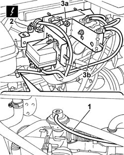
3. Undo the fixing nuts (3a) and move the mounting bracket (3b) complete with solenoid valve and heater plugs control unit aside.
Engines: 2.0 JTD 8V
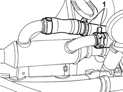
1. Disconnect the two engine coolant pipes on the exhaust gas heat exchanger.
Engines: 2.0 JTD 8V
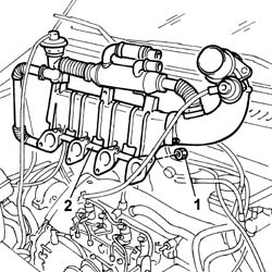
1. Undo the lower nuts and the upper bolts fixing the intake manifold to the cylinder head.- Lower the lift.2. Remove the intake assembly from the upper part of the engine compartment.
- Fit the intake assembly to the upper part of the engine compartment.- Raise the vehicle.- Tighten the lower nuts and the upper bolts fixing the intake manifold to the cylinder head to torque.
Value - daNm
Fastening
Component
Ø
.
2,3
Bolt
INLET MANIFOLD
-
Value - daNm
Fastening
Component
Ø
.
2,3
Nut
INLET MANIFOLD
-
- Connect the engine coolant pipes on the exhaust gas heat exchanger.- Fit the mounting bracket complete with solenoid valves and heater plugs control unit in the housing.- Tighten the bulkhead fixing nuts.- Connect the electrical connection for the heater plugs control unit.
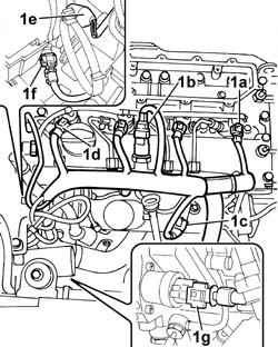
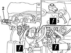
See in Op. 1060F201. Disconnect the electrical connections:
Description
Connector
1a
Injector
N070A
Description
Connector
1a
Injector
N070B
Description
Connector
1a
Injector
N070C
Description
Connector
1a
Injector
N070D
Description
Connector
1b
Fuel pressure sensor
K083
Description
Connector
1c
Air pressure - temperature sensor
K044
Description
Connector
.
Heater plugs
A040A
Description
Connector
.
Heater plugs
A040B
Description
Connector
.
Heater plugs
A040C
Description
Connector
.
Heater plugs
A040D
Description
Connector
1d
Timing sensor
K047
Description
Connector
1e
Coolant temperature sending unit (for instrument panel)
K035
Description
Connector
1f
Engine coolant temperature sensor/sender unit
K036
Description
Connector
1g
Fuel pressure regulator
N077
- Release the wiring from the bands and move it to the side.
Engines: 2.3 JTD 16V
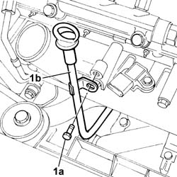
1. Undo the fixing bolt (1a) and remove the engine oil dipstick pipe (1b).
Engines: 2.3 JTD 16V
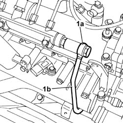
1. Undo the connector (1a) and disconnect the fuel pipe (1b) from the fuel manifold.
Engines: 2.3 JTD 16V
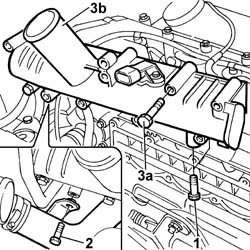
1. Undo the lower fixing bolts (1a) joining the intake manifold to the bracket for the rigid water supply pipes (1b) from the thermostat.2. Undo the bolt fixing the water supply pipe to the pump.3. Undo the fixing bolts (3a) and remove the air intake manifold (1b).- Recover the underlying gasket.
- Fit the new metal rubber intlet manifold gasket.- Fit the intake manifold.- Tighten the bolts fixing the intake manifold to the cylinder head to torque.
Value - daNm
Fastening
Component
Ø
.
2.5
Bolts
INLET MANIFOLD
M8
- Tighten the bolt fixing the pump water supply rigid pipe bracket to the intake manifold.- Tighten the bolt fixing the engine oil dipstick pipe.- Screw in the connector for the return pipe from the single fuel manifold to the return manifold and tighten it to torque.
Value - daNm
Fastening
Component
Ø
.
4
Connector
INJECTOR FUEL MANIFOLD (DIESEL)
M16
- Position the injection wiring and connect the electrical connections disconnected previously.
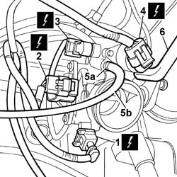
1. Disconnect the connection for the air temperature sensor.2. Disconnect the connection for the throttle opening sensor.3. Disconnect the connection for the idle air heater.4. Disconnect the connection for the idle speed adjustment stepping motor.5. Working on the retaining band (5a), release the petrol vapour recovery pipe (5b).6. Release the oil vapour recovery pipe.
Engines: 2.0 16V
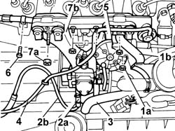
1. Undo the fixing nut (1a) and move the mounting bracket for the oil vapour separator (1b) aside.2. Work on the band (2a) and release the petrol vapour recovery pipe (2b).3. Release the oil vapour recovery pipe.4. Release the absolute pressure sensor pipe.5. Release the accelerator control cable and move it aside.6. Undo the bolt fixing the mounting bracket for the fuel supply pipe connector.7. Undo the fixing nuts (7a) and remove the intake manifold (7b).
- Fit the intake manifold.- Tighten the bolts fixing the intake manifold.- Tighten the bolt fixing the mounting bracket for the fuel supply pipe connector.- Position the accelerator control cable.- Position the absolute pressure sensor pipe.- Position the oil vapour recovery pipe.- Position the petrol vapour recovery pipe.- Tighten the band securing the petrol vapour recovery pipe.- Position the oil vapour separator mounting bracket.- Tighten the nut fixing the oil vapour separator mounting bracket.- Position the oil vapour recovery pipe.- Connect the electrical connection for the idle speed adjustment stepping motor.- Connect the electrical connection to the idle air heater.- Connect the electrical connection for the throttle opening sensor.- Connect the electrical connection for the air temperature sensor.- Connect the electrical connection for the detonation sensor.- Working on the connector, connect the coupling for the fuel supply pipe to the single manifold.- Connect the electrical connections for the injectors. Op. 1048A31 RIGID PIPE CONNECTING AIR CLEANER TO INLET MANIFOLD RIGID PIPE R R