FIAT / DUCATO 244eLearn workshop manual · English · Offline edition
Procedures

1088C30 THERMOSTAT UNIT - R+R

Engines: 2.0 16V, 2.0 JTD 8V, 2.3 JTD 16V
Engines: 2.0 JTD 8V

RemovingManual illustration 20

RefittingManual illustration 21
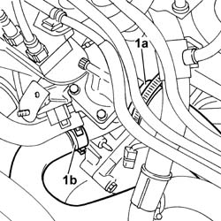
- Position the vehicle on the lift. Op. 7055B54 UNDER-ENGINE GUARD - R R See in Op. 1048A21 See in Op. 1048A50 Op. 1048B16 PIPES AND/OR ELBOW BETWEEN TURBOCHARGER AND THROTTLE CASING - R.R. Op. 1048B12 RIGID PIPE CARRYING AIR BETWEEN TURBOCHARGER AND INLET MANIFOLD - R+R- Position a suitable container for collecting the coolant.1. Disconnect the upper hose (1a) and the lower hose (1b) from the thermostat.
Manual illustration 244003115
Engines: 2.0 JTD 8V
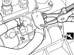
1. Using suitable pliers, open the bands retaining the coolant supply and return pipes to the engine oil heat exchanger.
Manual illustration 244000499DescriptionCodeFunction
.Caliper1.831.138.000Band opening
Manual illustration 244003116
Engines: 2.0 JTD 8V
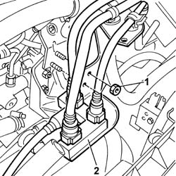
1. Undo the bolts fixing the fuel return manifold mounting bracket.2. Release the return manifold from the housing and place it outside of the work area.
Manual illustration 244003117
Engines: 2.0 JTD 8V
1. Disconnect the electrical connection for the water temperature sensor.
Manual illustration 244000463DescriptionConnector
1Engine coolant temperature sensor/sender unitK036
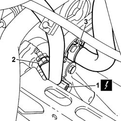
2. Disconnect the recirculation pipe.3. Disconnect the water pipe to the exhaust gas heat exchanger from the thermostat.
Manual illustration 244003118
Engines: 2.0 JTD 8V
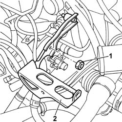
1. Undo the fixing nuts.2. Remove the turbocharger air outlet rigid pipe mounting bracket.
Manual illustration 244003119
Engines: 2.0 JTD 8V
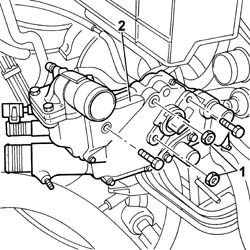
1. Undo the fixing nuts and bolts.2. Remove the thermostat unit from the housing in the cylinder head.
Manual illustration 244003120
Engines: 2.0 JTD 8V

RefittingManual illustration 21

RemovingManual illustration 20
- Fit the thermostat in the housing in the cylinderhead checking that it is correctly engaged with the rigid coolant pipe and tighten the fixing nuts and bolts to torque.
Manual illustration 244000559Value - daNmFasteningComponentØ  
.2boltCONTAINER GR. THERMOSTAT-
Manual illustration 244000559Value - daNmFasteningComponentØ  
.2NutCONTAINER GR. THERMOSTAT-
- Fit the turbocharger rigid air outlet pipe mounting bracket and tighten the fixing nuts.- Connect the water pipe to the exhaust gas heat exchanger to the thermostat.- Connect the recirculation pipe.- Connect the electrical connection for the water temperature sensor.
Manual illustration 244000463DescriptionConnector
.Engine coolant temperature sensor/sender unitK036
- Place the return manifold in position and tighten the fixing bolts.- Using suitable pliers, close the bands retaining the coolant supply and return pipes to the engine oil heat exchanger.
Manual illustration 244000499DescriptionCodeFunction
.Caliper1.831.138.000Band opening
- Connect the upper hose and the lower hose to the thermostat. Op. 1048B12 RIGID PIPE CARRYING AIR BETWEEN TURBOCHARGER AND INLET MANIFOLD - R+R Op. 1048B16 PIPES AND/OR ELBOW BETWEEN TURBOCHARGER AND THROTTLE CASING - R.R. See in Op. 1048A50 See in Op. 1048A21 Op. 0010T20 COOLANT CHECK DENSITY AND TOP UP IF NECESSARY Op. 7055B54 UNDER-ENGINE GUARD - R R- Remove the vehicle from the lift.
Engines: 2.3 JTD 16V

RemovingManual illustration 20

RefittingManual illustration 21
Op. 7055B54 UNDER-ENGINE GUARD - R R See in Op. 1088D181. Undo the upper and side bolts securing the timing belt protective cover.
Manual illustration 244003121
Engines: 2.3 JTD 16V
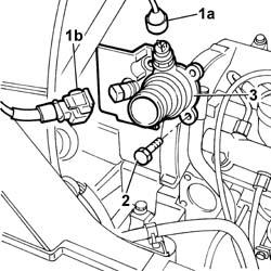
1. Disconnect thermostat electrical connections (1a) and (1b).
Manual illustration 244000463DescriptionConnector
1aCoolant temperature sending unit (for instrument panel)K035
Manual illustration 244000463DescriptionConnector
1bEngine coolant temperature sensor/sender unitK036
2. Undo the bolts securing the thermostat to the cylinder head.3. Remove the thermostat unit from the cylinder head.
Manual illustration 244003122
Engines: 2.3 JTD 16V

RefittingManual illustration 21

RemovingManual illustration 20
- Change the thermostat o-ring.- Fit the thermostat unit in its seat on the cylinder head.- Tighten the bolts securing the thermostat to the cylinder head to torque.
Manual illustration 244000559Value - daNmFasteningComponentØ  
.-BoltsTHERMOSTAT-
- Connect the electrical connections for the thermostat.
Manual illustration 244000463DescriptionConnector
.Coolant temperature sending unit (for instrument panel)K035
Manual illustration 244000463DescriptionConnector
.Engine coolant temperature sensor/sender unitK036
- Tighten the upper and side bolts securing the timing belt protective cover. See in Op. 1088D18 Op. 0010T20 COOLANT CHECK DENSITY AND TOP UP IF NECESSARY Op. 0010T21 COOLANT CHECK DENSITY AND TOP UP IF NECESSARY Op. 7055B54 UNDER-ENGINE GUARD - R R
Engines: 2.0 16V

RemovingManual illustration 20

RefittingManual illustration 21
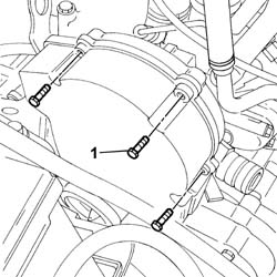
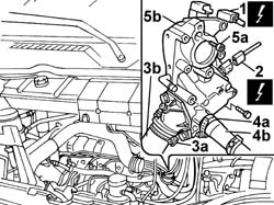
- Disconnect the negative battery terminal. See in Op. 1048A21 Op. 1048A39 SLEEVE FROM AIR CLEANER TO RIGID PIPE - R R Op. 5510C10 IGNITION COIL/S - R+R Op. 7055B54 UNDER-ENGINE GUARD - R R- Position a suitable container for collecting the coolant.- Lower the vehicle.1. Disconnect the electrical connection for the cam angle sensor.2. Disconnect the electrical connection for the engine coolant temperature sensor.3. Remove the band (3a) and relese the coolant oulet hose from the thermostat (3b).4. Remove the band (4a) and release the heater coolant supply pipe (4b).5. Undo the retaining bolts (5a) and remove the thermostat unit (5b).
Manual illustration 244003123
Engines: 2.0 16V

RefittingManual illustration 21

RemovingManual illustration 20
- Fit the thermostat unit in place.- Tighten the fixing bolts to the recommended torque.- Fit the thermostat unit inlet and outlet hoses and restore the bands removed previously.- Connect the electrical connection for the cam angle sensor.- Connect the engine coolant temperature sensor electrical connection. Op. 7055B54 UNDER-ENGINE GUARD - R R See in Op. 1048A21 Op. 1048A39 SLEEVE FROM AIR CLEANER TO RIGID PIPE - R R Op. 5510C10 IGNITION COIL/S - R+R Op. 0010T21 COOLANT CHECK DENSITY AND TOP UP IF NECESSARY- Connect the negative battery terminal.