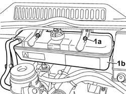
Drain the return pipe from the injectors to the return solenoid valve, following the instructions in the procedure:Op. 1043A02 LPG SYSTEM LINES PIPE DRAINING OPERATIONSDisconnect the negative battery terminal.1. Undo the nuts (1a) and move the engine coolant reservoir (1a) away from the work area, leaving the pipes connected.
Engines: 2.0 16V
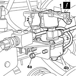
1. Disconnect the return solenoid valve electrical connector.
[symbol: elettrico.tif]
Description
Connector
1
LPG cut out solenoid valves
L063
2. Disconnect the connector for the rigid return pipe to the intermediate block.3. Disconnect the connector for the LPG rigid return pipe to the tank to the solenoid valve.4. Undo the nuts (4a) and remove the solenoid valve (4b) complete with rigid pipe.At the bench, separate the rigid pipe from the solenoid valve.
At the bench, screw in the connector for the rigid pipe on the solenoid valve without tightening it.Position the solenoid valve on the mounting bracket and fit the connector for the rigid pipe on the intermediate block.Tighten the nuts fixing the solenoid valve to the mounting bracket to torque.
[symbol: coppie.tif]
Value daNm
Fastening
Component
Ø
-
0.9
Nut
mounting bracket
M6
Tighten the connector for the rigid return pipe to the solenoid valve to the recommended torque.
[symbol: coppie.tif]
Value daNm
Fastening
Component
Ø
-
1.5
Connector
on the return solenoid valve
M10 X 1
Tighten the connector for the rigid return pipe to the intermediate block to the recommended torque.
[symbol: coppie.tif]
Value daNm
Fastening
Component
Ø
-
2.5
Connector
on the intermediate block
M12 X 1
Screw in and tighten the connector for the LPG rigid return pipe to the tank to the recommended torque.
[symbol: coppie.tif]
Value daNm
Fastening
Component
Ø
-
1.5
Connector
on the solenoid valve
M10 X 1
Connect the return solenoid valve electrical connector.