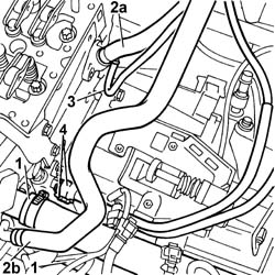
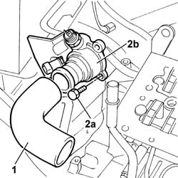
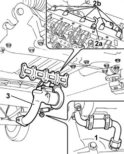
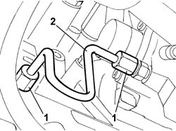
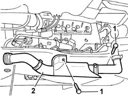
1. Disconnect the sleeve from the thermostat and from the rigid pipe, then remove.2. Undo retaining bolts (2a) and remove thermostat (2b).
Engines: 2.3 JTD 16V
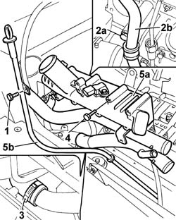
1. Undo the bolt securing the engine oil dipstick tube.2. Undo bolt (2a) securing the rigid outlet pipe to pump (2b).3. Disconnect the coolant outlet sleeve to the engine oil heat exchanger.4. Undo the bolts securing the exhaust manifold to the cylinder head.5. Remove intake manifold (5a) together with the engine oil dipstick pipe (5b).
Engines: 2.3 JTD 16V
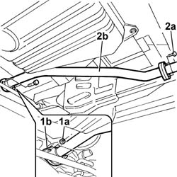
Raise the vehicle.1. Undo retaining nuts (1a) and separate rigid intermediate section (1b) of the exhaust pipe from the turbocharger sleeve flange.2. Undo the bolts fixing the rear flange (2a) and remove the rigid middle section (2b) of the exhaust pipe.
Engines: 2.3 JTD 16V
1. Disconnect the connector for the turbocharger sump oil return pipe.Lower the vehicle.2. Undo fitting (2a) and disconnecft the rigid oil delivery pipe to the turbocharger. Also unscrew nuts (2b) securing the exhaust manifold to the cylinder head.3. Remove the exhaust manifold complete with turbocharger from the lower part of the vehicle from the compartment between the suspension beam and body.
Engines: 2.3 JTD 16V
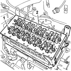
1. Undo the retaining bolts.2. Remove the cylinder head from its seat on the engine block.Recover the cylinder head gasket on the engine block.
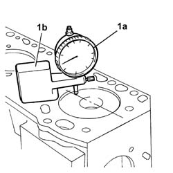
1. Measure piston protrusion from the upper engine block surface in order to determine the thickness of gasket to be used. For this purpose, use dial gauge (1a) supported by magnetic base (1b), previously zeroed on the engine block surface. Measure piston protrusion by taking a measurement at the piston pin centre line.After checking piston recess or protrusion from the upper engine block surface, fit an appropriate gasket to maintain the compression ratio within permitted tolerances.
Engines: 2.3 JTD 16V
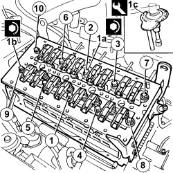
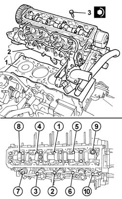
Keep the gasket sealed in its plastic bag and do not remove from its protection until ready to fit.Do not lubricate the gasket or contaminate with oil or grease.Position the cylinder head on the cylinder block/crankcase.Undo the support clips and remove the bracket.1. Tighten bolts (1a) and (1b) retaining the cylinder head to the engine block to the specified torque in the sequence shown in the figure and using tool (1c) for angular tightening.- For positions numbered from 1 to 6, tighten to the torque values indicated below:
Value daNm
Fastening
Component
Ø
1a
10±0,5+90°±5°+90°±5°
Bolt
CYLINDER HEAD
M14
- For positions numbered from 7 to 10, tighten to the torque values indicated below:
Value daNm
Fastening
Component
Ø
1b
5±0,25+60°±3°+60°±3°
Bolts
CYLINDER HEAD
M14
Description
Code
Function
1c
Torque wrench
1.860.942.000
Cylinder head bolts angular tightening
Engines: 2.3 JTD 16V
Lift the vehicle and fit the exhaust manifold complete with turbocharger.Tighten the nuts securing the exhaust manifold to the cylinder head to torque.
Value daNm
Fastening
Component
Ø
.
2.2
Nut
EXHAUST MANIFOLD/S
M8
Connect the rigid oil supply pipe to the turbocharger to the crankcase and tighten the connector.Lower the vehicle.Connect the rigid oil supply pipe to the turbocharger to the crankcase and tighten the connector.Connect the connector for the turbocharger sump oil return pipe.Fit the exhaust pipe intermediate rigid pipe section.Tighten the retaining nuts on the turbocharger flange to torque.
Value daNm
Fastening
Component
Ø
.
2.6
Nuts
EXHAUST PIPE TO ENGINE
M8
Tighten the exhaust pipe intermediate section retaining bolts to the rear flange.
Value daNm
Fastening
Component
Ø
.
2.6
Bolt
REAR SILENCER EXHAUST
M8
Lower the lift.Fit the intake manifold and the engine oil dipstick tube.Tighten the bolts fixing the intake manifold to the cylinder head to torque.
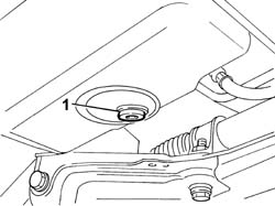
Op. 7055B54 UNDER-ENGINE GUARD - R R- Arrange a container beneath the engine to recover the engine oil.1. Undo the plug on the oil sump and drain the oil.
Engines: 2.0 JTD 8V
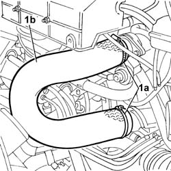
Op. 4130B10 POWER STEERING FLUID RESEVOIR R RCharacteristic of working principle 1. Open the retaining band (1a) and disconnect the pipe (1b) joining the turbocharger to the ntake manifold.
Engines: 2.0 JTD 8V
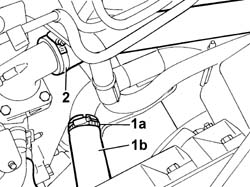
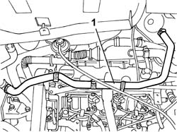
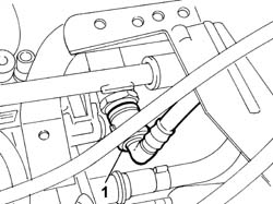
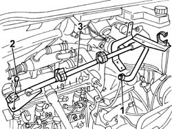
- Arrange a container beneath the engine to recover the engine coolant.1. Disconnect band (1a) and disconnnect the lower radiator pipe from rigid section (1b).2. Disconnect the upper pipe from the thermostat.
Engines: 2.0 JTD 8V
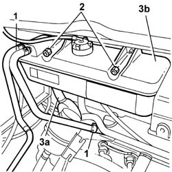
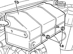
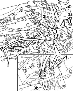
1. Disconnect the band retaining the coolant pipe to the cylinder head.2. Undo the nuts securing the reservoir to the bodyshell.3. Disconnect sleeve (3a) from the rigid pipe and remove expansion tank (3b).
Engines: 2.0 JTD 8V
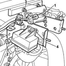
1. Undo bolts (1a) and remove the protective cover (1b) for the glow plug control unit.
Engines: 2.0 JTD 8V
1. Disconnect the electrical connection for the glow plug control unit.
Description
Connector
1
Heater plugs control unit
M015C
2. Undo the nut securing the glow plug control unit to the bracket.- Release the wiring from the bands and replace the control unit on the engine.
Engines: 2.0 JTD 8V
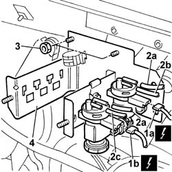
1. Disconnect the electrical connections of the exhaust gas recirculation regulation solenoid (1a) and the throttle body solenoid (1b).
Description
Connector
1a
EGR solenoid valve
L030
Description
Connector
1b
Throttle body solenoid valve
L062
2. Remove vacuum pipes (2a), vacuum pipe to the EGR (2b) and the vacuum pipe to the pneumatic valve on the throttle body (2c) from the solenoids.3. Undo the retaining nuts.- . Remove the bracket from the engine compartment.
Engines: 2.0 JTD 8V
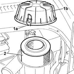
1. Open retaining clips (1a) and remove protective cover (1b) from the filter element.2. Remove the filter element from the filter casing.
Engines: 2.0 JTD 8V
1. Disconnect the electrical connection for the air flow meter.
Description
Connector
1
Air flow meter
K041
2. Undo the nuts securing the filter casing to the bracket.3. Disconnect the band securing the air flow meter to the air delivery pipe to the turbo.4. Remove the air filter casing.
Engines: 2.0 JTD 8V
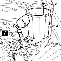
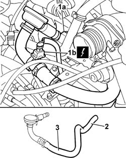
1. Press the retaining spring (1a) and disconnect the electrical connection (1b) for the engine oil vapour pipe.
Description
Connector
1b
Oil vapour heating resistance
O007A
2. Disconnect the engine oil vapour pipe from the air intake pipe between the filter and the turbocharger.3. Remove the oil vapour pipe.
Engines: 2.0 JTD 8V
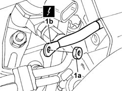
1. Undo the retaining nut (1a) and disconnect the supply lead from the glow plugs (1b).
Description
Connector
1b
Heater plugs
A040
Engines: 2.0 JTD 8V
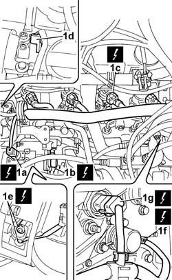
1. Disconnect the electrical connections:
Description
Connector
1a
Injection pump third piston deactivation solenoid valve
L005
Description
Connector
1b
Fuel pressure regulator
N077
Description
Connector
.
Fuel pressure sensor
K083
Description
Connector
1c
Injector
N070A
Description
Connector
1c
Injector
N070B
Description
Connector
1c
Injector
N070C
Description
Connector
1c
Injector
N070D
Description
Connector
1d
Timing sensor
K047
Description
Connector
.
Engine oil pressure sensor
K028
Description
Connector
1e
Alternator
A010A
Description
Connector
1e
Alternator
A010B
Description
Connector
1f
Rpm sensor
K046
Description
Connector
1g
Engine coolant temperature sensor/sender unit
K036
Description
Connector
.
Starter motor
A020A
Description
Connector
.
Starter motor
A020B
- Release the wiring from the bands and move it to the side.
Engines: 2.0 JTD 8V
1. Disconnect the three quick-release connectors on the fuel lines from the fuel return manifold.2. Disconnect the quick-release connectors on both fuel lines from the pressure pump.3. Undo retaining bolt (I3a), disconnect injector recirculation pipe (3b) and remove return manifold (3c) complete with pipes.
Engines: 2.0 JTD 8V
1. Remove the water supply pipe from the heater.
Engines: 2.0 JTD 8V
1. Disconnect the quick-release connector from the vacuum pump.
Engines: 2.0 JTD 8V
1. Disconnect the recirculation hose from the thermostat.2. Undo the retaining bolt.3. Remove the rigid section of the water recirculation pipe from the cylinder head.
Engines: 2.0 JTD 8V
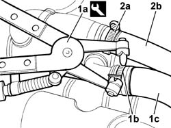
1. Use tool (1a) to open undo band (1b) and disconnect the water pipe (1c) to the thermostat.
Description
Code
Function
.
Spanner
1.881.138.000
cylinder head - r + r and replace gasket
2. Open band (2a) and disconnect pipe (1b) from the EGR exhaust gas heat exchanger.
Engines: 2.0 JTD 8V
1. Use an appropriate wrench to open the bands and disconnect both coolant delivery and return pipes to the engine oil heat exchanger.
Description
Code
Function
.
Spanner
1.881.138.000
cylinder head - r + r and replace gasket
2. Remove the rubber hose from the cam cover to the engine oil vapour separator.3. Remove the flexible section of the lower engine coolant pipe.
Engines: 2.0 JTD 8V
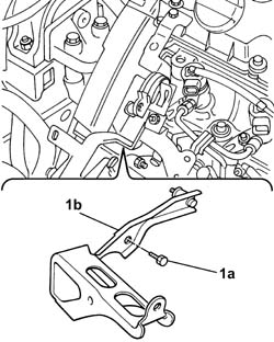
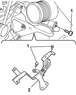
1. Undo retaining bolts (1a) and remove bracket (1b).
Engines: 2.0 JTD 8V
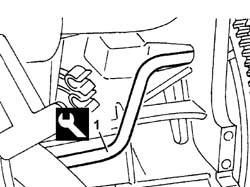
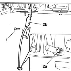
1. Undo the upper bolts securing the engine oil dipstick tube.2. Undo the lower bolt (2a) and remove the engine oil dipstick tube (2b).
Engines: 2.0 JTD 8V
1. Undo the connectors on the fuel manifold and pressure pump.2. Remove the fuel delivery pipe from pressure pump to fuel manifold.
Engines: 2.0 JTD 8V
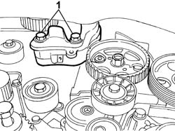
1. Undo the retaining bolts.2. Remove the bracket on the thermostat.
Engines: 2.0 JTD 8V
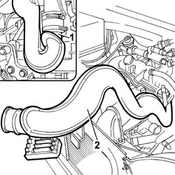
- Raise the vehicle.Characteristic of working principle 1. Open the band securing the pipe to the turbocharger.2. Remove the rigid pipe from the upper part of the engine bay.
Engines: 2.0 JTD 8V
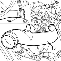
1. Open retaining band (1a) and remove rigid pipe (1b) from the upper part of the engine bay.
Engines: 2.0 JTD 8V
1. Remve the press-fitted EGR pipe heat shield.
Engines: 2.0 JTD 8V
1. Undo the bolt securing the lower reaction rod to the suspension crossmember.2. Undo the bolt securing the lower reaction rod to the mounting bracket on the gearbox.- Move the power unit slightly forward to make enough room to remove the reaction link.- Remove the lower reaction link.
Engines: 2.0 JTD 8V
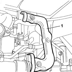
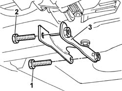
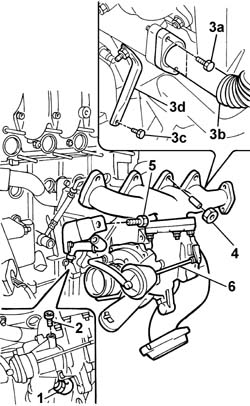
1. Disconnect the band for the turbocharger sump oil return pipe.2. Undo the connector and disconnect the turbocharger rigid oil supply pipe.3. Undo retaining bolts (3a) and disconnect the EGR exhaust gas delivery pipe from the turbocharger (3B).4. Undo the nuts securing the exhaust manifold to the cylinder head.5. Undo the bolt securing the turbocharger to the mounting bracket.- Move the power unit forward.6. Remove the exhaust manifold complete with turbocharger from the lower part of the vehicle from the compartment between the suspension beam and body.
Engines: 2.0 JTD 8V
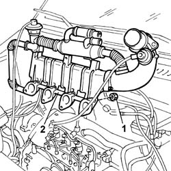
1. Unscrew the lower and upper bolts securing the intake manifold to the cylinder head.- Lower the lift.2. Remove the intake manifold from the upper part of the engine compartment.
Engines: 2.0 JTD 8V
- Refit the reaction link in its seat and screw in the retaining bolts without tightening.1. Undo the bolts securing the rigid water inlet pipe to the pump.2. Remove the rigid water intake pipe to the pump.
Engines: 2.0 JTD 8V
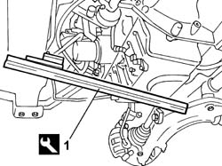
1. Position the tool for supporting the power unit fastened to the crossmember for the suspension and to the lower crossmember under the engine oil sump.
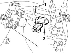
1. Undo the retaining bolt.2. Remove the rpm sensor.
Engines: 2.0 JTD 8V
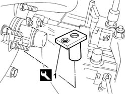
1. Fit the flyhwheel lock into its seat on the rpm sensor.
Description
Code
Function
1
Flywheel lock
1.870.765.001
Prevent flywheel rotation
Engines: 2.0 JTD 8V
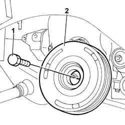
1. Undo bolts (1a) and remove the auxiliary shaft drive pulley (1b).
Engines: 2.0 JTD 8V
- Remove the flywheel lock fitted previously.
Description
Code
Function
.
Flywheel lock
1.870.765.001
Prevent flywheel rotation
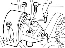
1. Undo the nuts securing the block to the bodyshell.2. Undo the bolts securing the flexible block to the rigid mounting on the engine.3. Remove the flexible mounting from the engine compartment.
Engines: 2.0 JTD 8V
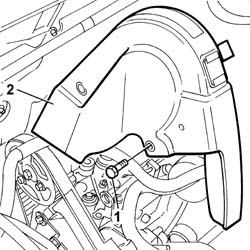
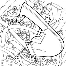
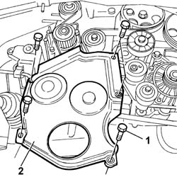
1. Undo the retaining bolts.2. Remove the timing belt upper guard.
Engines: 2.0 JTD 8V
1. Undo the retaining bolts.2. Remove the timing belt side guard.
Engines: 2.0 JTD 8V
- Raise the lift.1. Undo the retaining bolts.2. Remove the timing belt lower guard.
Engines: 2.0 JTD 8V
1. Slowly turn the crankshaft until the TDC positioning tool fits into the seat on the flywheel.
Description
Code
Function
1
Pin
1.860.863.000
Positioning engine at TDC
Engines: 2.0 JTD 8V
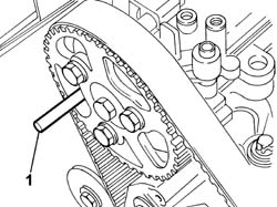
- Lower the vehicle.1. Fit an 8 mm diameter camshaft timing adjustment pin nto its seat on the cylinder head.
Engines: 2.0 JTD 8V
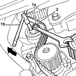
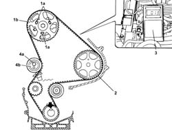
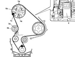
1. Loosen bolt (1a) and use a ¼" box wrench (1b) to slacken belt tension. Then tighten the nut unscrewed previously.2. Remove the timing belt.
Engines: 2.0 JTD 8V
1. Unscrew the power unit rigid lower mount bolts.
Engines: 2.0 JTD 8V
1. Undo the bolt (1a) and remove the timing sensor (1b)
Engines: 2.0 JTD 8V
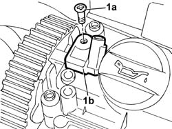
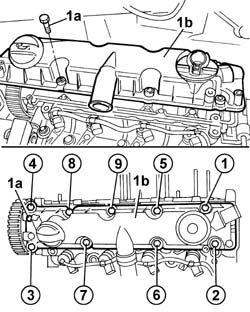
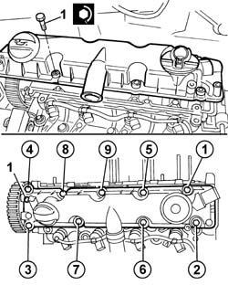
1. Undo bolts (1a) in the order shown and remove cam cover (1b).
Engines: 2.0 JTD 8V
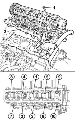
1. Undo the bolts securing the cylinder head to the crankase in the order shown.2. Remove the cylinder head assembly.3. Recover the underlying gasket.
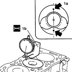
1. Measure piston projection (1a) in two places 180° apart on the piston pin centre line using tool (1b) and take the average of the two values measured for each piston.
Description
Code
Function
1b
Dial gauge support
1.870.404.000
Injector projection from cylinder head plane measurement
Engines: 2.0 JTD 8V
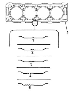
1. Select the correct size cylinder head gasket depending on the maximum average protrusions for each individual piston.
Subject
Value
1
CYLINDER HEAD GASKET
mm
-
Size
1,30
-
Average protrusion
0,470 - 0,605
Subject
Value
1
CYLINDER HEAD GASKET
mm
-
Size
1,35
-
Average protrusion
0,605 - 0,655
Subject
Value
1
CYLINDER HEAD GASKET
mm
-
Size
1,40
-
Average protrusion
0,655 - 0,705
Subject
Value
1
CYLINDER HEAD GASKET
mm
-
Size
1,45
-
Average protrusion
0,705 - 0,755
Subject
Value
1
CYLINDER HEAD GASKET
mm
-
Size
1,50
-
Average protrusion
0,755 - 0,830
Engines: 2.0 JTD 8V
- Keep the gasket sealed in its plastic bag and do not remove from its protection until ready to fit.- Do not lubricate the gasket or contaminate with oil or grease.- Position the cylinder head on the cylinder block/crankcase.- Undo the support clips and remove the bracket.1. Tighten the bolts fixing the cylinder head to the cylinder block to the recommended torque following the order illustrated and using the angular tightening tool.
Value - daNm
Fastening
Component
Ø
.
2+6+220°
Bolts
CYLINDER HEAD
-
Description
Code
Function
.
Torque wrench
1.860.942.000
Connecting rod cap bolt tightening
Engines: 2.0 JTD 8V
- Fit the tappet cover in its housing on the cylinder head.1. Tighten the bolts fixing the tappet cover to torque in the order given below.
Value - daNm
Fastening
Component
Ø
.
1,0
Bolt
CAM COVER
-
Engines: 2.0 JTD 8V
- Fit the timing sensor into its housing in the cam cover.- Tighten the power unit rigid mount lower bolts.1. Loosen bolts (1a) securing the camshaft pulley (1b).2. Fit the timing belt over the pulleys in order.- Check that the engine is at TDC and the camshaft reference is aligned.3. Fit the C-TRONIC - 105.5 tool facing downward.4. Unscrew bolt (4a) securing tensioner (4b) and use a ¼" box wrench to tension the belt to the specified value.
Subject
Value
.
Timing belt/s
unità seem
-
Timing belt tension
108
- Tighten the tensioner bolt and the pulley bolts.- Remove the C-TRONIC - 105.5 tool.- Fit the timing belt pulley bolt provisionally so that the crankshaft can be turned.- Crank the engine through 8 revolutions without going backward.
Engines: 2.0 JTD 8V
- Turn the engine clockwise without going back until the TDC reference tool fits into its seat on the flywheel.
Description
Code
Function
.
Pin
1.860.863.000
Crankshaft TDC reference
1. Loosen bolts (1a) securing the pulley (1b), then position the 8 mm timing reference pin (1c) through the pulley into its seat on the cylinder head.2. Fit the C-TRONIC - 105.5 tool facing downward.3. Unscrew bolt (3a) securing tensioner (3b) and use a ¼" box wrench to tension the belt to the specified value.
Subject
Value
.
Timing belt/s
unità seem
-
Timing belt tension
54
Engines: 2.0 JTD 8V
- Tighten the tensioner bolt and the timing pulley bolts.- Remove the C-TRONIC - 105.5 tool.- Refit the C-TRONIC - 105.5 too and check that the belt tension is within specified values.
Subject
Value
.
Timing belt/s
unità seem
-
Timing belt tension
51 - 57
- Remove the C-TRONIC - 105.5 tool.- Remove the TDC reference tool.
Description
Code
Function
.
Pin
1.860.863.000
Crankshaft TDC reference
- Remove the 8 mm diameter timing reference tool.- Turn the engine through two revolutions clockwise without going back until the TDC reference tool fits into its seat on the flywheel.
Description
Code
Function
.
Pin
1.860.863.000
Crankshaft TDC reference
- Check that the 8 mm diameter timing reference pin fits through the pulley into its seat on the cylinder head extension.- If not, loosen the pulley bolts and turn the camshaft anticlockwise until the 8 mm diameter timing reference pin fits through the pulley into its seat on the cylinder head extension.- Tighten the pulley retaining bolts.- Repeat the check.- Remove the TDC reference tool.
Description
Code
Function
.
Pin
1.860.863.000
Crankshaft TDC reference
- Remove the 8 mm diameter timing reference tool.- Tighten the bolts securing the pulley to the recommended torque.
Value - daNm
Fastening
Component
Ø
.
2,0
Bolt
TIMING DRIVEN PULLIES
-
- Tighten the tensioner retaining bolt to the recommended torque.
Value - daNm
Fastening
Component
Ø
.
2,3
Bolt
MOBILE TIMING TENSIONER
-
- Position the timing belt lower guard and tighten the retaining bolts.- Position the timing belt side guard and tighten the retaining bolts.- Position the timing belt upper guard and tighten the retaining bolts.- Fit the flexible mounting in the housing in the engine compartment.- Tighten the nuts securing the flexible mounting to the bodyshell.
Value - daNm
Fastening
Component
Ø
.
(body block) 5
Nuts
FRONT FLEXIBLE MOUNTING BLOCKS, POWER UNIT
M10
- Tighten the nut and the two bolts fixing the flexible mounting to the timing side rigid power unit support to torque.
Value - daNm
Fastening
Component
Ø
.
(Rigid mount on engine) 5
Bolt
FRONT FLEXIBLE MOUNTING BLOCKS, POWER UNIT
M10
Value - daNm
Fastening
Component
Ø
.
(Rigid mount on engine) 8
Nut
FRONT FLEXIBLE MOUNTING BLOCKS, POWER UNIT
M12
- Fit the flywheel lock.
Description
Code
Function
.
Flywheel lock
1.870.765.001
Prevent flywheel rotation
- Fit the auxiliary drivebelt pulley and tighten the retaining bolt to torque using the angular tightening tool.
Value - daNm
Fastening
Component
Ø
.
4+51°
Bolt
CRANKSHAFT PULLEY
-
Description
Code
Function
.
Torque wrench
1.860.942.000
Connecting rod cap bolt angular tightening
- Remove the flywheel lock fitted previously.
Description
Code
Function
.
Counter-torque
1.860.765.001
Loosen/tighten toothed timing drive pulley bolt
- Fit the rpm sensor in its housing on the gearbox bell housing and tighten the retaining bolt.- Connect the electrical connection for the rpm sensor.
- Fit the rigid inlet water pipe on the pump.- Remove the reaction link from its seat again.- Fit the intake manifold from the upper part of the engine compartment.- Raise the vehicle.- Tighten the lower nuts and upper bolts securing the intake manifold to the cylinder head to torque.
Value - daNm
Fastening
Component
Ø
.
2,3
Bolt
INLET MANIFOLD
-
- Fit the exhaust manifold complete with turbocharger from the lower part of the vehicle from the compartment between the suspension beam and body.- Tighten the bolt securing the turbocharger to the mounting bracket.- Tighten the nuts securing the exhaust manifold to the cylinder head.
Value - daNm
Fastening
Component
Ø
.
2,0
Nut
EXHAUST MANIFOLD/S
-
- Connect the EGR exhaust gas delivery pipe from the turbocharger and tighten the retaining bolts.- Connect the rigid oil supply pipe to the turbocharger and tighten the connector.- Connect the band for the turbocharger sump oil return pipe.- Fit the lower reaction rod in the housing and tighten the bolt fixing the suspension crossmember to torque.- Tighten the nut fixing the reaction rod to the gearbox to torque.- Fit the press-fitted EGR pipe heat shield.- Fit the rigid air intake pipe to the turbo from the upper part of the engine bay and do up the retaining band.- Fit the rigid air outlet pipe from the turbocharger from the upper part of the engine bay and do up the lower band on the turbocharger.Characteristic of working principle - Lower the vehicle.- Fit the bracket on the thermostat and tighten the fixing bolts.- Fit the new pipe from the pressure pump to the fuel manifold.- Tighten the connectors on the pressure pump and on the return manifold to torque.
Value - daNm
Fastening
Component
Ø
.
2
Connector
PRESSURE PUMP LINE TO FUEL MANIFOLD
-
- Fit the engine oil dipstick tube and tighten the retaining bolts.- Fit the bracket located near the pressure pump mounting and tighten the bolts.- Fit the flexible section of the lower engine coolant pipe.- Fit the rubber hose from the cam cover to the engine oil vapour separator.- Connect the two supply and return pipes to the thermostat from the engine oil oil heat exchanger.- Connect the supplementary heater coolant pipe and the thermostat pipe to the EGR exhaust gas heat exchanger.- Fit the rigid section of the water recirculation pipe to the cylinder head and tighten the retaining bolts.- Connect the water recirculation hose from the thermostat.- Connect the quick-release connector of the vacuum pump pipe.- Fit the heater water supply pipe.- Fit the fuel return manifold and connect the fuel recirculation pipe from the injectors.- Tighten the retaining bolt and connect the quick release fittings of both fuel pipes from the pressure pump.- Connect the three quick-release connectors on the fuel lines to the fuel return manifold.- Position the injection wiring and connect the electrical connections.
Description
Connector
.
Injection pump third piston deactivation solenoid valve
L005
Description
Connector
.
Fuel pressure regulator
N077
Description
Connector
.
Fuel pressure sensor
K083
Description
Connector
.
Injector
N070A
Description
Connector
.
Injector
N070B
Description
Connector
.
Injector
N070C
Description
Connector
.
Injector
N070D
Description
Connector
.
Timing sensor
K047
Description
Connector
.
Engine oil pressure sensor
K028
Description
Connector
.
Alternator
A010A
Description
Connector
.
Alternator
A010B
Description
Connector
.
Rpm sensor
K046
Description
Connector
.
Engine coolant temperature sensor/sender unit
K036
Description
Connector
.
Starter motor
A020A
Description
Connector
.
Starter motor
A020B
- Tighten the nut securing the spark plug supply lead.- Fit the engine oil vapour pipe and connect to the air intake pipe between the filter and the turbocharger.- Connect the electrical connection for the engine oil vapour pipe.
Description
Connector
.
Oil vapour heating resistance
O007A
- Secure the oil vapour pipe to the cam cover.- Fit the air filter casing and connect the air flow meter retaining band to the air delivery pipe to the turbo.- Tighten the nuts securing the filter casing to the bracket.- Connect the electrical connection for the air flow meter.
Description
Connector
.
Air flow meter
K041
- Fit the filter element between the filter case and the cover. Secure with clips.- Fit the support bracket located near the thermostat and tighten the nuts.- Connect the vacuum pipes, vacuum pipe to the EGR and the vacuum pipe to the pneumatic valve on the throttle body to the solenoids.- Connect the electrical connections of the exhaust gas recirculation regulation solenoid and the throttle body solenoid (1b).
Description
Connector
.
Throttle body solenoid valve
L062
Description
Connector
.
EGR solenoid valve
L030
- Fit the glow plug control unit into its seat on the bracket and tighten the retaining nut.- Connect the electrical connection for the glow plug control unit.
Description
Connector
.
Heater plugs control unit
M015C
- Fit the protective cover for the heater plugs control unit and tighten the fixing bolts.- Fit the engine coolant reservoir and connect the engine coolant sleeves to this.- Tighten the nuts securing the reservoir to the bodyshell.- Connect the upper coolant pipe from the thermostat.- Connect the lower radiator hose to the rigid section of the pipe.- Fit the intake manifold turbocharger connection pipe.Characteristic of working principle Op. 4130B10 POWER STEERING FLUID RESEVOIR R ROp. 0010T20 COOLANT CHECK DENSITY AND TOP UP IF NECESSARYOp. 0010T10 ENGINE OIL CHECK LEVEL AND TOP UP