FIAT / DUCATO 244eLearn workshop manual · English · Offline edition
Procedures

7040A97 FACIA TRIM SUPPORT BEAM - R R

Engines: 2.0 16V, 2.0 JTD 8V, 2.3 JTD 16V, 2.8 JTD 8V

RemovingManual illustration 20

RefittingManual illustration 21
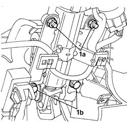
- Disconnect the negative battery terminal. Op. 5580C18 AIR BAG MODULE - R+R Op. 4110A10 STEERING WHEEL - R+R FOR REPLACEMENT OR CHECKS Op. 7040A26 STEERING COLUMN TRIM - R+R Op. 7040A23 FRAME OF INSTRUMENT PANEL ON FACIA - R R Op. 7040A18 GLOVE COMPARTMENT ON FACIA - ARRANGE Op. 7040A19 CUSHION PADDING - R R Op. 7040A20 LEFT DASHBOARD LOWER TRIM - R.R. Op. 7040A07 UPPER COMPARTMENT ON FACIA - R R Op. 7040A78 RADIO COMPARTMENT BOX R R Op. 7040A72 UPPER CENTRAL DOCUMENT HOLDER ON DASHBOARD - R.R . Op. 7065C42 ASHTRAY (ONE) R+R Op. 7065C10 AIR CONDITIONING CONTROL PANEL - R+R Op. 7065C53 ASHTRAY COMPARTMENT FLAP-R R Op. 7040A28 TRIM ON GEARBOX CONTROL PANEL - R.R. Op. 5560C22 TACHOGRAPH - R.R. Op. 7040A60 UNDER FACIA TRIM - R+R Op. 7040A04 FACIA LOWER TRIM-R R Op. 5010C12 WINDSCREEN DEMISING VENT - R.R.- Op. 7040A39 DEVICE FOR DRIVER`S SEAT SQUAB LUMBAR ADJUSTMENT - R R- < R1 > [All] Op. 7040A10 L/H OR R/H FRONT SEAT (ONE) - R+R- < R1 > [All]-1. Undo the nuts (1a) and the bolts (1b) fixing the steering column to the crossmember.
Manual illustration 244004705
Engines: 2.0 16V, 2.0 JTD 8V, 2.3 JTD 16V, 2.8 JTD 8V
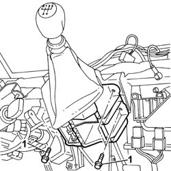
- Remove the bonnet release lever.1. Undo the bolts fixing the gearbox control lever support.- Move the support aside.
Manual illustration 244004706
Engines: 2.0 16V, 2.0 JTD 8V, 2.3 JTD 16V, 2.8 JTD 8V
- Disconnect the electrical connectors from the CODE control unit located under the gear lever.
Manual illustration 244000463DescriptionConnector
.CODE control unitM020A
Manual illustration 244000463DescriptionConnector
.CODE control unitM020B
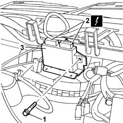
1. Undo the bolts fixing the electric windows and central locking control unit.2. Disconnect the electrical connectors from the electric windows and central locking control unit.
Manual illustration 244000463DescriptionConnector
2Electric windows/central locking control unitM135A
Manual illustration 244000463DescriptionConnector
2Electric windows/central locking control unitM135B
3. Remove the electric windows and central locking control unit.
Manual illustration 244004707
Engines: 2.0 16V, 2.0 JTD 8V, 2.3 JTD 16V, 2.8 JTD 8V
- Undo the bolts fixing the climate control unit to the crossmember.- Disconnect the relays for the air conditioning fan.
Manual illustration 244000463DescriptionConnector
.Passenger compartment air fan speed relay 1J034
Manual illustration 244000463DescriptionConnector
.Passenger compartment air fan maximum speed relayJ041
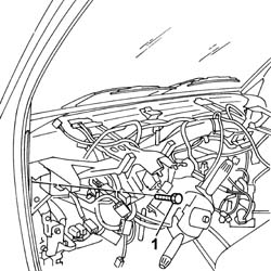
- Open the dashboard wiring retaining bands.1. Undo the bolts fixing the crossmember to the bodyshell.
Manual illustration 244004708
Engines: 2.0 16V, 2.0 JTD 8V, 2.3 JTD 16V, 2.8 JTD 8V

RefittingManual illustration 21

RemovingManual illustration 20
- Fasten the crossmember to the bodyshell tightening the fixing bolts to the recommended torque.
Manual illustration 244000559Value - daNmFasteningComponentØ  
.3,6BoltCROSSMEMBER SUPPORTING DASHBOARD TRIMM10 X 1.25
- Fasten the climate control unit tightening the bolts fixing it to the crossmember.- Connect the relays for the air conditioning fan.
Manual illustration 244000463DescriptionConnector
.Passenger compartment air fan speed relay 1J034
Manual illustration 244000463DescriptionConnector
.Passenger compartment air fan maximum speed relayJ041
- Fasten the electric windows/central locking control unit to the crossmember tightening the fixing bolts.- Connect the electrical connectors to the electric windows and central locking control unit.
Manual illustration 244000463DescriptionConnector
2Electric windows/central locking control unitM135A
Manual illustration 244000463DescriptionConnector
2Electric windows/central locking control unitM135B
- Connect the electrical connectors to the CODE control unit
Manual illustration 244000463DescriptionConnector
.CODE control unitM020A
Manual illustration 244000463DescriptionConnector
.CODE control unitM020B
- Fasten the gear lever support to the crossmember tightening the fixing bolts.- Fit the bonnet release lever.- Fasten the support and steering control shafts to the dashboard supporting crossmember tighten the nuts and bolts to the recommended torque.
Manual illustration 244000559Value - daNmFasteningComponentØ  
.1,5NutSTEERING SHAFT MOUNTINGM8
Manual illustration 244000559Value - daNmFasteningComponentØ  
.1,5BoltSTEERING SHAFT MOUNTINGM8
Op. 7040A10 L/H OR R/H FRONT SEAT (ONE) - R+R Op. 7040A39 DEVICE FOR DRIVER`S SEAT SQUAB LUMBAR ADJUSTMENT - R R- < R1 > [All] Op. 5010C12 WINDSCREEN DEMISING VENT - R.R.- < R1 > [All] Op. 7040A04 FACIA LOWER TRIM-R R Op. 7040A60 UNDER FACIA TRIM - R+R Op. 5560C22 TACHOGRAPH - R.R. Op. 7040A28 TRIM ON GEARBOX CONTROL PANEL - R.R. Op. 7065C53 ASHTRAY COMPARTMENT FLAP-R R Op. 7065C10 AIR CONDITIONING CONTROL PANEL - R+R Op. 7065C42 ASHTRAY (ONE) R+R Op. 7040A72 UPPER CENTRAL DOCUMENT HOLDER ON DASHBOARD - R.R . Op. 7040A78 RADIO COMPARTMENT BOX R R Op. 7040A07 UPPER COMPARTMENT ON FACIA - R R Op. 7040A20 LEFT DASHBOARD LOWER TRIM - R.R. Op. 7040A19 CUSHION PADDING - R R Op. 7040A18 GLOVE COMPARTMENT ON FACIA - ARRANGE Op. 7040A23 FRAME OF INSTRUMENT PANEL ON FACIA - R R Op. 7040A26 STEERING COLUMN TRIM - R+R Op. 4110A10 STEERING WHEEL - R+R FOR REPLACEMENT OR CHECKS Op. 5580C18 AIR BAG MODULE - R+R- Connect the negative battery terminal.