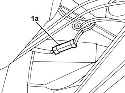
Drain the section of pipe from the repressurizing filler to the tank and the LPG supply and return pipes from the tank to the solenoid valve assembly / G4-G5, following the procedure and the instructions described below:Op. 1043A02 LPG SYSTEM LINES PIPE DRAINING OPERATIONSReturn the vehicle to the workshop and place on a lift.Disconnect the negative battery terminal.Op. 1043E12 GPL TANK GUARD PROTECTION R R1. Disconnect the electrical connector for the tank supply device (1a).
[symbol: elettrico.tif]
Description
Connector
1a
Device for electric supply of LPG tank
M017
Engines: 2.0 16V
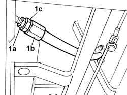
1. Undo the connector (2a) for the LPG filler pipe (2b) keeping the connector (2c) locked.
Engines: 2.0 16V
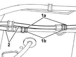
1. Undo the connectors (1a) keeping the connectors (1b) locked.2. Disconnect the LPG supply and return pipes.
Engines: 2.0 16V
Position the tool for supporting the tank on a hydraulic lift designed to support the weight of the tank and suitably protected so as not to spoil the paintwork; place the tool under the LPG canister.
[symbol: attrezzi.tif]
Description
Code
Function
-
Support
1.870.833.000
LPG tank removal
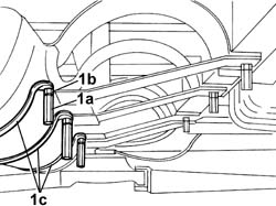
1. Undo the bushes (1a) housing the guard fixing bolts and the fixing nuts (1b), keep the bushes and the nuts and remove the collars (1c).Lower the hydraulic lift and remove the tank complete with supply and return pipes and electrical wiring.
Engines: 2.0 16V
With the help of a second operator, remove the tank complete with supply and return pipes and electrical wiring; position the tank on suitable supports.