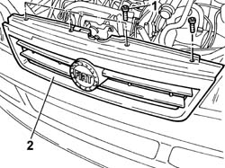
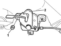
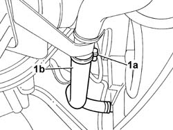
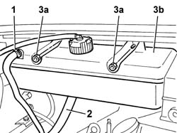
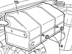
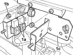
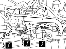
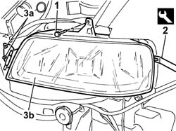
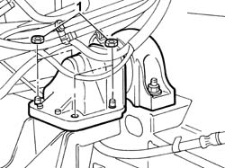
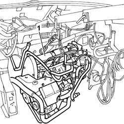
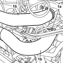
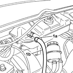
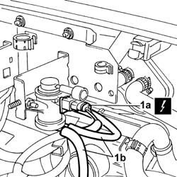
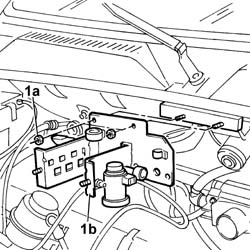
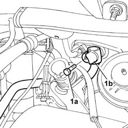
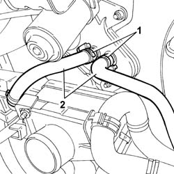
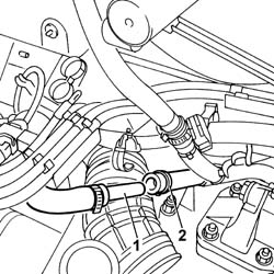
- Lower the vehicle.1. Disconnect the retaining band and release the coolant pipe on the reservoir.2. Work on the band and disconnect the water pump fluid supply pipe.3. Undo the fixing nuts (3a) and remove the expansion tank (3b).
Engines: 2.0 16V
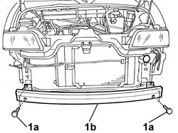
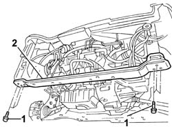
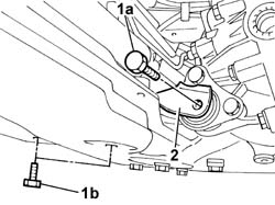
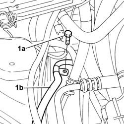
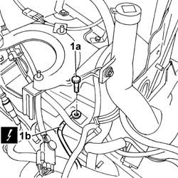
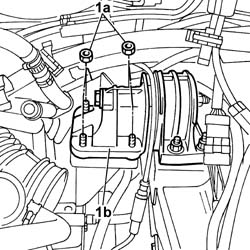
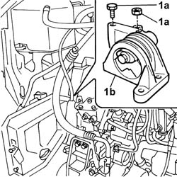
1. Undo the fixing bolts (1a) and remove the crossmember (1b).
Engines: 2.0 16V
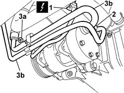
- Raise the vehicle.1. Disconnect the electrical connection.2. Undo the bolt fixing the pipes to the compressor.3. Undo the nut fixing the bracket (3a) and move the pipes (3b) aside.
Engines: 2.0 16V
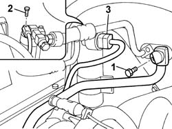
1. Undo the bolt fixing the connector to the expansion valve.2. Undo the bolt fixing the connector to the drier filter.- Release the pipes from the fastenings.
Engines: 2.0 16V
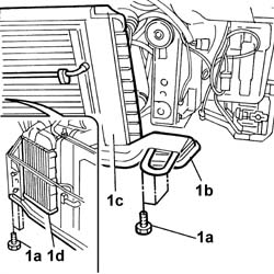
1. Undo the fixing bolts (1a) and the nut (1b) and remove the side plastic shield (1c).2. Undo the fixing bolts and disconnect the connectors from the condenser.3. Release the pipes from the retaining springs and remove it.
Engines: 2.0 16V
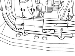
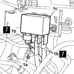
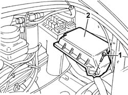
1. Undo the fixing bolts (1a) and remove the protective cover (1b) for the relays.
Engines: 2.0 16V
1. Release the relays from the bracket and move them aside.2. Undo the fixing nuts (2a) and remove the bracket (2b).
Engines: 2.0 16V
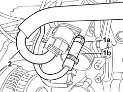
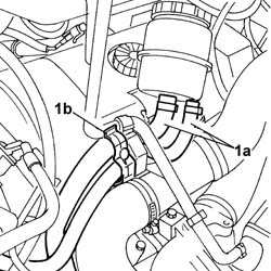
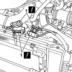
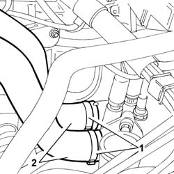
1. Remove the retaining band (1a) and release the hose from the thermostat (1b).2. Disconnect the electrical connections for the fans.3. Disconnect the electrical connections from the resistor.4. Remove the plastic fastening bands and move the electrical lead aside.
Engines: 2.0 16V
- Disconnect the left and right front light cluster electrical connection.
Description
Connector
.
Left headlamp
F010
Description
Connector
.
Right headlamp
F011
1. Unscrew the upper light cluster retaining bolt.2. Use a suitable tool (2a) to prise light cluster from its seat, while releasing the pin from the opening in the wing.
Description
Code
Function
2a
Knife
1.078.077.000
Prise light cluster out of beam
3. Undo the nuts fixing the hinges for the left light cluster (3a) and remove the left front light cluster (3b).- Repeat the same operation on the right front light cluster.
Description
Code
Function
2a
Knife
1.078.077.000
Prise light cluster out of beam
Engines: 2.0 16V
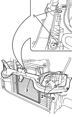
1. Unscrew the nuts and bolts securing the upper beam located inside the light cluster seats.2. Remove the upper crossmember from the engine compartment.
Engines: 2.0 16V
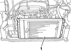
1. Remove the radiator and condenser assembly.
Engines: 2.0 16V
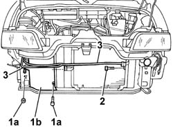
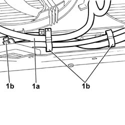
1. Undo the fixing nuts (1a) for the cable mounting bracket (1b) and move it aside.2. Release the leads from the fastenings on the radiator supporting crossmember and move them aside.
Engines: 2.0 16V
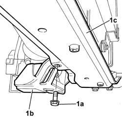
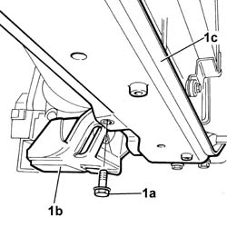
1. Undo the bolt (1a) fixing the ABS control unit (1b) mounting bracket to the mass supporting crossmember (1c).
Engines: 2.0 16V
- Partly raise the lift.1. Undo the fixing bolts.2. Remove the radiator supporting crossmember.
Engines: 2.0 16V
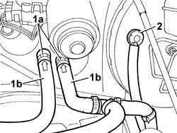
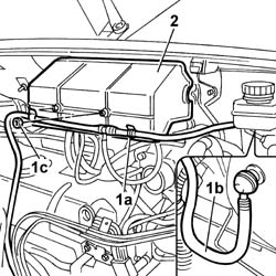
1. Remove the bands (1a) and release the pipes (1b).2. Disconnect the brake servo vacuum pipe.
Engines: 2.0 16V
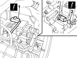
- Disconnect the electrical connection for the multi-stage valve.1. Disconnect the electrical connection for the cam angle sensor.2. Disconnect the electrical connection for the air temperature sensor.
Engines: 2.0 16V
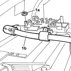
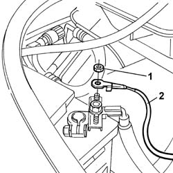
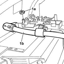
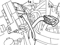
1. Undo the fixing nut (1a) and disconnect the positive lead (1b) from battery control unit.
Engines: 2.0 16V
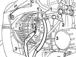
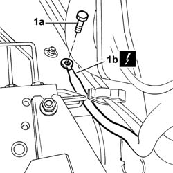
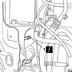
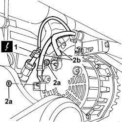
- Undo the bolt fixing the negative lead to the side member.- Disconnect the connection for the ABS sensor.1. Remove the plastic protective caps.2. Undo the fixing nuts.3. Disconnect the cables and move them aside.
Description
Connector
3
Alternator
A010A
Description
Connector
3
Alternator
A010B
Engines: 2.0 16V
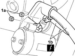
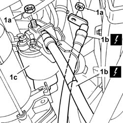
1. Remove the protective boot, undo the fixing nuts (1a) and disconnect the electrical wiring for the starter mtor (1b).
Description
Connector
1b
Starter motor
A020A
Description
Connector
1b
Starter motor
A020B
Engines: 2.0 16V
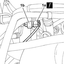
1. Remove the retaining band (1a) and disconnect the petrol vapour recovery pipe (1b) from the throttle casing.2. Disconnect the pipe on the throttle casing coming from the oil vapour heater.
Engines: 2.0 16V
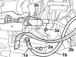
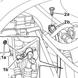
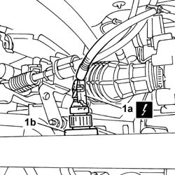
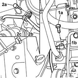
1. Disconnect the electrical connection for the reversing lights switch (1a) and move the electrical wiring (1b) aside.2. Undo the bolt (2a) and move the earth lead (2b) fastened to the gearbox aside.3. Undo the fixing nuts (3a) and move the clutch actuator cylinder (3b) aside.
Engines: 2.0 16V
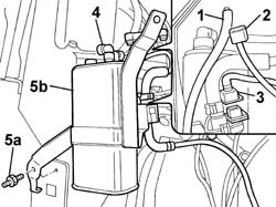
1. Disconnect the small pipe from the absolute pressure sensor.2. Disconnect the electrical connection frrom the pressure sensor.3. Disconnect the electrical connection from the fuel vapour enablement solenoid valve.4. Disconnect the rapid connector for the pipe coming from the petrol vapour separator from the active charcoal filter.5. Undo the bolt fixing the active charcoal filter mounting bracket (5a) and remove the active charcoal filter complete with bracket.
Engines: 2.0 16V
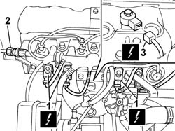
1. Disconnect the electrical connections for the injectors.2. Working on the nut, disconnect the coupling for the fuel supply pipe and the single manifold.3. Disconnect the electrical connection from the detonation sensor.
Engines: 2.0 16V
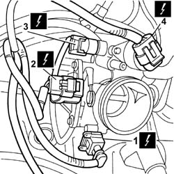
1. Disconnect the electrical connection for the air temperature sensor.2. Disconnect the electrical connection for the throttle position sensor.3. Disconnect the electrical connection for the idle air heater.4. Disconnect the electrical connection for the stepping actuator on the throttle casing.
Engines: 2.0 16V
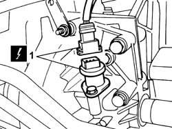
- Raise the vehicle.1. Disconnect the electrical connections for the Lambda sensors.
Engines: 2.0 16V
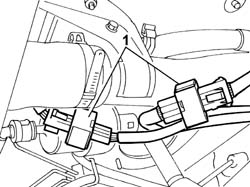
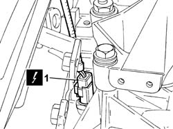
1. Disconnect the electrical connection for the speedometer sensor.
Engines: 2.0 16V
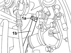
- Lower the vehicle.1. Remove the band (1a) and disconnect the fuel return pipe (1b) from the single fuel manifold.
Engines: 2.0 16V
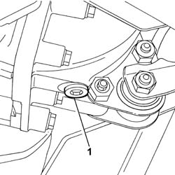
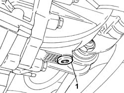
- Raise the vehicle.- Have a suitable container for collecting the transmission fluid ready.1. Undo the plug, using a suitable spanner, and drain the transmission fluid.
Description
Code
Function
.
Spanner
1.850.182.000
Wrench for slackening/tightening differential fluid plug
Engines: 2.0 16V
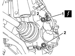
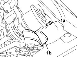
1. Disconnect the electrical connection for the left front brake pad wear sensor cable.2. Undo the bolts fixing the brake caliper to the bracket and move it aside without disconnecting the oil pipe.
Engines: 2.0 16V
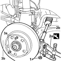
1. Undo the nut fixing the track rod end to the steering knuckle.2. Extract the track rod end (2b) from the housing in the steering knuckle using the tool (2a).3. Undo the centering pins (3a) and remove the brake disc (3b).
Description
Code
Function
2a
Head extractor
1.847.038.000
Ball joint removal
Engines: 2.0 16V
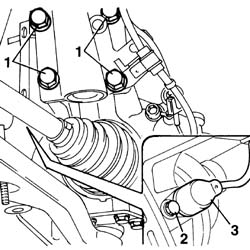
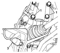
1. Undo the bolts fixing the steering knuckle to the shock absorber.2. Undo the fixing bolt.3. Remove the left ABS sensor from the housing and place it outside the work area.
Engines: 2.0 16V
1. Undo the bolts fixing the stub axle to the steering knuckle.
Engines: 2.0 16V
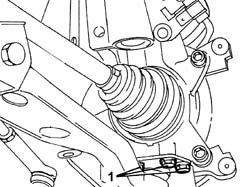
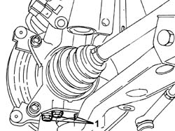
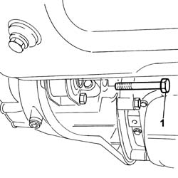
1. Undo the fixing bolt (1a) and remove the casing (1b).
Engines: 2.0 16V
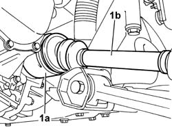
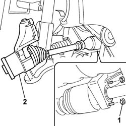
1. Release the inner driveshaft (1a) from the housing on the differential, then remove the driveshaft - steering knuckle assembly (1b).
Engines: 2.0 16V
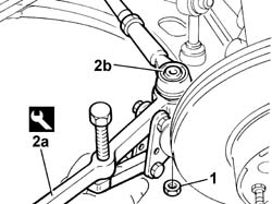
1. Undo the nut fixing the track rod end to the steering knuckle.2. Extract the track rod end (2b) from the housing in the steering knuckle using the tool (2a).
Description
Code
Function
2a
Head extractor
1.847.038.000
Ball joint removal
Engines: 2.0 16V
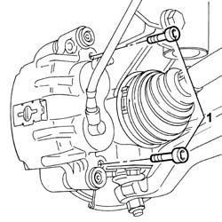
1. Undo the bolts fixing the brake caliper to the bracket and move it aside without disconnecting the oil pipe.
Engines: 2.0 16V
1. Undo the bolts fixing the steering knuckle to the shock absorber.2. Undo the fixing bolt.3. Remove the right ABS sensor from the housing and place it outside the work area.
Engines: 2.0 16V
1. Undo the bolts fixing the stub axle to the steering knuckle.
Engines: 2.0 16V
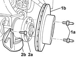
1. Undo the fastening pins (1a) and remove the brake disc (1b).2. Undo the fixing bolt (2a) and remove the casing (2b).
Engines: 2.0 16V
1. Undo the nuts fixing the intermediate driveshaft to the support.2. Remove the intermediate driveshaft - right driveshaft assembly complete with steering knuckle.
Engines: 2.0 16V
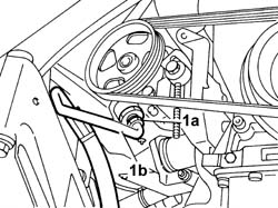
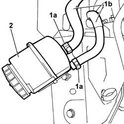
- Position a suitable container for collecting the power assisted steering fluid.1. Undo the connector (1a) fastening the rigid pipe to the pump and move the pipe (1b) aside.
Engines: 2.0 16V
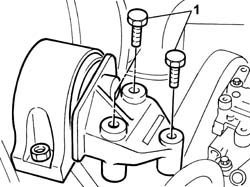
1. Undo the bolt fixing the lower engine support (1a) and undo the bolts fixing the lower engine mounting bracket (1b).2. Move the engine mounting bracket aside.
Engines: 2.0 16V
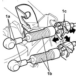
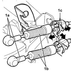
1. Release the two ends (1a), move the two gear selector and engagement flexible cables (1b) out of the slot in the bracket (1c) and place them outside of the work area.
Engines: 2.0 16V
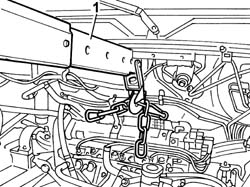
1. Secure the power unit to a hydraulic lift for its removal.
Engines: 2.0 16V
- Place a support under the power unit to rest the power unit on later on.1. Undo the bolts fixing the flexible mounting to the timing side rigid power unit support.
Engines: 2.0 16V
1. Undo the nuts fixing the gearbox side flexible mounting to the rigid support.
Engines: 2.0 16V
1. Manoeuvre the power unit acting on the hydraulic lift and lower it slowly until it is resting on the support.- Raise the vehicle and extract the support placing it away from the actual vehicle.
- Support the power unit by means of a hydraulic lift with chains and position the power unit in its compartment on the vehicle.- Tighten the nuts fixing the gearbox side flexible mounting to the rigid support.
Value - daNm
Fastening
Component
Ø
.
(Rigid mount) 5
Nuts
GEARBOX SIDE RUBBER MOUNT
M10
- Tighten the nut and the two bolts fixing the flexible mounting to the timing side rigid power unit support to torque.
Value - daNm
Fastening
Component
Ø
.
(Rigid mount on engine) 5
Bolt
FRONT FLEXIBLE MOUNTING BLOCKS, POWER UNIT
M10
Value - daNm
Fastening
Component
Ø
.
(Rigid mount on engine) 8
Nut
FRONT FLEXIBLE MOUNTING BLOCKS, POWER UNIT
M12
- Remove the hydraulic lift for removing the power unit.- Remove the hydraulic lift for removing the power unit.- Connect both ends of the gear selection and engagement cables and secure them to the mounting bracket.- Position the engine mounting bracket.- Tighten the bolts fixing the lower engine mounting bracket to torque.
Value - daNm
Fastening
Component
Ø
.
0,4 - 0,8
Bolt
ENGINE ASSEMBLY
M6
- Fit the lower reaction rod in the housing and tighten the bolt fixing it to the engine support to torque.- Fit the intermediate driveshaft - right driveshaft assembly complete with steering knuckle and brake disc.- Tighten the nuts fixing the intermediate driveshaft to the support to torque.- Tighten the bolts fixing the stub axle to the steering knuckle to torque.- Fit the right ABS sensor in its housing and tighten the retaining bolt.- Tighten the bolts fixing the steering knuckle to the shock absorber to torque.
Value - daNm
Fastening
Component
Ø
.
damper to shock absorber) 19
Bolts
FRONT HUB STRUT
M16
- Fit the brake caliper - bracket assembly and tighten the bolts fixing the bracket to the left disc to torque.
Value - daNm
Fastening
Component
Ø
.
21
Bolt
FRONT BRAKE CALIPER BRACKET
M16
- Tighten the nut fixing the ball joint to the steering rod to torque.
Value - daNm
Fastening
Component
Ø
.
6.9
Nut
ADJUSTABLE LINK BALL JOINTS
M16
- Fit the left driveshaft assembly and press fit the inner driveshaft in the housing on the left differential.- Tighten the bolts fixing the stub axle to the left hub to torque.- Fit the right ABS sensor in its housing and tighten the retaining bolt.- Tighten the bolts fixing the steering knuckle to the shock absorber to torque.
Value - daNm
Fastening
Component
Ø
.
damper to shock absorber) 19
Bolts
FRONT HUB STRUT
M16
- Tighten the nut fixing the ball joint to the steering rod to torque.
Value - daNm
Fastening
Component
Ø
.
6.9
Nut
ADJUSTABLE LINK BALL JOINTS
M16
- Fit the brake caliper - bracket assembly and tighten the bolts fixing the bracket to the left disc to torque.
Value - daNm
Fastening
Component
Ø
.
21
Bolt
FRONT BRAKE CALIPER BRACKET
M16
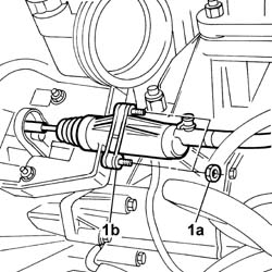
- Connect the engine coolant return pipe to the heater.- Connect the fluid supply pipe to the power assisted steering box and tighten the connector.- Connect the fuel pipes to the return manifold, securing them to the retaining bands.- Connect the gearbox earth lead to the bodyshell.- Connect the electrical connections and reposition the junction unit in the casing.- Fit the engine compartment junction unit protective cover and tighten the fixing bolt.- Connect the electrical connection for the speedometer sensor.- Connect the electrical connection for the reversing light switch.- Connect the electrical connections for the engine management control unit.- Place the clutch release cylinder in the housing and tighten the fixing bolts.- Fit the lower radiator pipe, tighten the bolts fixing it to the bellhousing and connect the hose to the thermostat.- Fit the air filter casing.- Tighten the nuts fixing the filter casing to the mounting bracket.- Connect the electrical connection for the air flow meter.- Fit the filter element in the filter casing and fit the protective cover securing it using the fastenings.- Connect the single-acting valve to the brake servo.- Fit the junctiton unit and solenoid valve mounting bracket and tighten the fixing nuts.- Fit the engine coolant reservoir and connect the coolant hoses.- Fit the radiator supporting crossmember and tighten the fixing bolts to torque.
Value - daNm
Fastening
Component
Ø
.
8.5
Bolt
COOLANT RADIATOR SUPPORT BEAM
M12
- Connect the electrical wiring for the starter motor.- Connect the alternator electrical wiring.- Connect the electrical connection for the right front wheel A.B.S. sensor.- Tighten the fixing bolt and connect the earth lead to the bodyshell.- Fit the radiator assembly complete with fans.- Fit the engine coolant reservoir and connect the coolant hoses.- Connect the electrical connections for the fans.- Tighten the bolt fixing the side plastic shield.- Fit the upper radiator pipe and connect it to the thermostat and to the radiator.- Connect the lower radiator hose to the rigid section of the pipe.- Fit the upper crossmember in the engine bay complete with front light clusters.- Tighten the retaining bolts and nuts to torque.
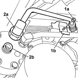
1. Undo the nut (1a) fixing the air conditioning pipes mounting bracket (1b).2. Undo the air conditioning pipe connector (2a) from the compressor (2b).
1. Undo the nut (1a) fixing the air conditioning pipes mounting bracket (1b).2. Undo the fixing bolt (2a) and remove the return pipe (2b) from the evaporator to the drier filter.
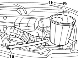
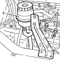
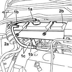
1. Disconnect the breather pipe (1a) from the expansion tank and open the bands (1b) and disconnect the pipes (1c).2. Undo the fixing nuts (2a) and remove the expansion tank (2b).
1. Open the retaining springs (1a) and disconnect the single-acting valve (1b) on the brake servo, then undo the nuts (1c).2. Remove the protective cover.
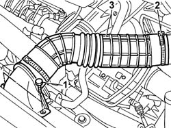
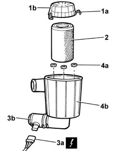
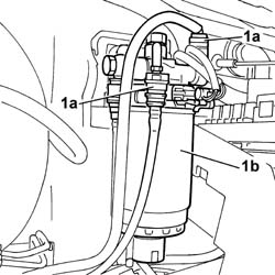
1. Open the retaining springs (1a) and remove the filter casing cover (1b).2. Remove the filter element.3. Disconnect the electrical connection (3a) and open the securing band (3b).
Description
Connector
3a
Air flow meter
K041
4. Undo the fixing nuts (4a) and remove the air filter casing (4b).
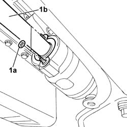
1. Release the two ends (1a), move the two gear selector and engagement flexible cables (1b) out of the slot in the bracket (1c) and place them outside of the work area.
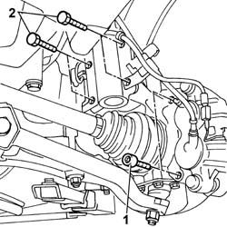
1. Undo the fixing bolts.- Carry out the same operation for both brake calipers and move them outside of the work area.2. Undo the bolts fixing the shock absorber hub.- Carry out the same operation on both shock absorber hubs.
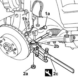
1. Undo the bolt (1a) fixing the ABS sensor (1b) and move it aside.- Carry out the same operation on both front ABS sensors.2. Undo the nut (2a) fixing the track rod end (2b) and extract it using the special tool (2c).- Carry out the same operation on both track rod ends.
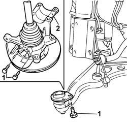
1. Undo the track control arm stub axle fixing bolts.- Carry out the same operation on both track control arms.2. Remove the steering knuckle hub complete with driveshaft.- Carry out the same operation on both hubs complete with driveshaft and right side intermediate driveshaft.
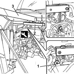
1. Fit the two brackets secured to the engine.2. Position the tool and secure to the brackets positioned previously.3. Secure the tool to a hydraulic lift for supporting and removing the power unit.
- Support the power unit by means of a hydraulic lift with chains and position the power unit in its compartment on the vehicle.- Fit the power unit inside the engine compartment.- Tighten the fastenings securing the flexible mounting to the gearbox side rigid support to torque.
Value - daNm
Fastening
Component
Ø
.
(Flexible block on rigid mount) 5
Nut
GEARBOX SIDE RUBBER MOUNT
M10 X 1.25
- Tighten the fastenings securing the flexible mounting to the timing side rigid support to torque.
Value - daNm
Fastening
Component
Ø
.
(Flexible block on rigid mount) 8
Bolt
FRONT FLEXIBLE MOUNTING BLOCKS, POWER UNIT
M12 X 1.25
- Remove the tool and hydraulic lift for supporting and removing the power unit.
Description
Code
Function
.
Crossmember
1.860.851.000
Power unit anchorage beam
- Remove the two brackets secured to the engine.- Connect the additional heater pipe and tighten the retaining band.- Connect the rapid connector pipes to the fuel filter.- Fit the steering knuckle hub complete with driveshaft for both hubs in position.- Tighten the bolts fixing the track control arm stub axle for both track control arms.- Tighten the nuts fixing the intermediate driveshaft to the support to torque.- Fit the steering track rod ends in position and tighten the nut for both to torque.
Value - daNm
Fastening
Component
Ø
.
6.9
Nut
ADJUSTABLE LINK BALL JOINTS
M16
- Fit the ABS sensor in place and tighten the fixing bolt, carry out the same operation on both sides.- Tighten the bolt fixing the steering knuckle to the shock absorber to torque and carry out the same operation on both hubs.
Value - daNm
Fastening
Component
Ø
.
(damper strut) 19
Bolt
FRONT HUB STRUT
M16
- Fit the brake caliper-bracket assembly and tighten the bolts fixing the bracket to the disc to torque and carry out the same operation for both brake calipers.
Value - daNm
Fastening
Component
Ø
.
21
Bolt
FRONT BRAKE CALIPER BRACKET
M16
- Tighten the bolt fixing the reaction rod to the differential to torque.- Tighten the bolt fixing the power assisted steering rigid pipe connector to the power assisted steering pump to torque.- Tighten the bolt fixing the retaining bracket for the power assisted steering fluid rigid pipe.- Connect the electrical connection for the oil pressure sensor.
Description
Connector
.
Engine oil pressure sensor
K028
- Tighten the fixing nuts and connect the leads to the alternator. Op. 1080B62 CATALYTIC CONVERTER - R + R- Connect the electrical connection for the speedometer sensor on the gearbox.
Description
Connector
.
Speedometer sensor
K084
- Fit both heads of the gear selection and engagement cables and secure them to the bracket.- Connect the electrical connector for the right side ABS sensor.
Description
Connector
.
Right front wheel sensor for ABS
K071
- Connect the electrical connection for the multi-stage pressure switch.
Description
Connector
.
4 stage pressure switch
K010
- Connect the electrical connection for the reversing light switch.
Description
Connector
.
Reversing lights switch
I020
- Tighten the fixing bolt and connect the earth on the bodyshell.
Description
Connector
.
Battery earth
C001
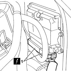
- Connect the electrical connections for the engine management control unit.
Description
Connector
.
Engine management control unit
M010A
Description
Connector
.
Engine management control unit
M010B
- Connect the electrical connections to the junction unit.
Description
Connector
.
Engine compartment junction unit
B001C
Description
Connector
.
Front/facia coupling
D001A
- Position the junction unit in its seat on the mount and fit the protective cover tightening the fixing bolt.- Fit the clutch release cylinder and tighten the retaining bolts to the bracket.- Place the filter casing in position and tighten the fixing nuts.- Fit the filter mass inside the filter casing.- Fit the filter casing cover and close it using the retaining springs.- Connect the electrical connection for the air flow meter.
Description
Connector
.
Air flow meter
K041
- Fit the heater pipes in place and secure them using the retaining bands.- Fit the air conditioning rigid pipe in place and tighten the bolt.- Fit the EGR solenoid valve and heat-flange relay mounting bracket.- Fit the pipes on the EGR solenoid valve and connect the electrical connection.
Description
Connector
.
EGR solenoid valve
L030
- Connect the electrical connections to the heat flange relay.
Description
Connector
Heat-flange relay
J130A
Description
Connector
Heat-flange relay
J130B
Description
Connector
Heat-flange relay
J130C
- Fit the EGR solenoid valve and heater plugs control unit cover and tighten the fixing nuts.- Fit the single-acting valve in place on the brake servo and secure it to the retaining springs.- Place the expansion tank in position and tighten the fixing nuts.- Fit the pipes to the tank and secure them using the retaining bands.- Fit the radiator and heat exchanger (intercooler) supporting crossmember and secure it tightening the fixing bolts to torque.
Value - daNm
Fastening
Component
Ø
.
8.5
Bolt
COOLANT RADIATOR SUPPORT BEAM
M12
- Fit the hoses to the thermostat and secure them with the retaining bands.- Connect the return pipe from the evaporator to the drier filter and secure it using the fixing bolt.- Tighten the fixing bolt and connect the earth on the bodyshell.
Description
Connector
.
Battery earth
C001
- Connect the positive lead ot the battery control unit and secure it using the fixing nut.- Connect the earth lead to the bodyshell and secure it using the fixing bolt.- Connect the starter motor wiring using the nuts.
Description
Connector
.
Starter motor
A020A
Description
Connector
.
Starter motor
A020B
- Fit the wiring on the crossmember and secure it using the retaining springs.- Tighten the connectors for the air conditioning rigid pipes on the compressor.- Secure the compressor rigid pipes to the mounting bracket and tighten the fixing nut.- Tighten the bolt fixing the ABS control unit support to the engine cooling radiator supporting crossmember.- Fasten the earth lead to the bodyshell using the bolt.