FIAT / DUCATO 244eLearn workshop manual · English · Offline edition
Procedures

1036B10 OVERHEAD CAMSHAFT - R R ON VEHICLE

Engines: 2.0 16V, 2.0 JTD 8V, 2.8 JTD 8V
Engines: 2.0 16V

RemovingManual illustration 20

RefittingManual illustration 21
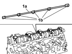
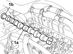
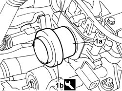
See in Op. 1048A21 Op. 1048A39 SLEEVE FROM AIR CLEANER TO RIGID PIPE - R R Op. 5510C10 IGNITION COIL/S - R+R Op. 7055B54 UNDER-ENGINE GUARD - R R See in Op. 1088C30 Op. 1048A31 RIGID PIPE CONNECTING AIR CLEANER TO INLET MANIFOLD RIGID PIPE R R See in Op. 1016A20 Op. 1092C11 POWER STEERING PUMP DRIVE BELT - R R FOR VERSIONS WITH AIR CONDITIONER Op. 1092B40 AIR CONDITIONER COMPRESSOR/ALTERNATOR DRIVE BELT - R + R See in Op. 1092A12 See in Op. 1032D12 See in Op. 1032B14 Op. 1032B53 DRIVEN TOOTHED PULLEY (ONE) - R R FOR VERSIONS WITH AIR CONDITIONER1. Remove the lubrication pipe (1a) which is a press fit and the seals (1b).
Manual illustration 244002477
Engines: 2.0 16V
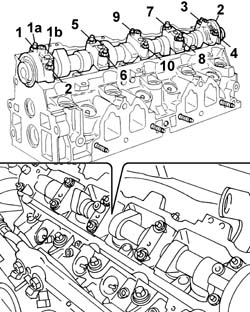
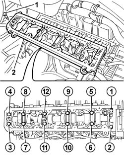
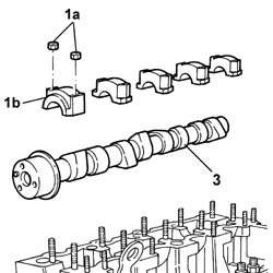
1. Undo the nuts (1a) fixing the camshaft caps in the order indicated and remove the caps (1b).2. Remove the camshaft.- Remove the camshaft front oil seal.
Manual illustration 244002478
Engines: 2.0 16V

RefittingManual illustration 21

RemovingManual illustration 20
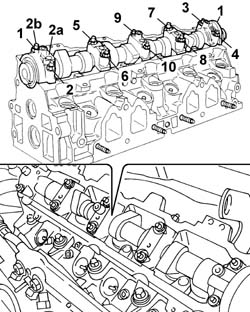
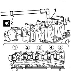
1. Fit the camshaft.2. Fit the camshaft caps (2a) and tighten the nuts (2b) to the recommended torque following the order given.
Manual illustration 244000559Value - daNmFasteningComponentØ  
2b1,6NutCAMSHAFT CAPS-
Manual illustration 244002479
Engines: 2.0 16V
- Press fit the lubrication pipe and the seals. See in Op. 1036B36 Op. 1032B53 DRIVEN TOOTHED PULLEY (ONE) - R R FOR VERSIONS WITH AIR CONDITIONER See in Op. 1032B14 See in Op. 1032D12 See in Op. 1092A12 Op. 1092B40 AIR CONDITIONER COMPRESSOR/ALTERNATOR DRIVE BELT - R + R Op. 1092C11 POWER STEERING PUMP DRIVE BELT - R R FOR VERSIONS WITH AIR CONDITIONER See in Op. 1016A20 Op. 1048A39 SLEEVE FROM AIR CLEANER TO RIGID PIPE - R R Op. 5510C10 IGNITION COIL/S - R+R Op. 7055B54 UNDER-ENGINE GUARD - R R See in Op. 1088C30 Op. 1048A31 RIGID PIPE CONNECTING AIR CLEANER TO INLET MANIFOLD RIGID PIPE R R Op. 0010T21 COOLANT CHECK DENSITY AND TOP UP IF NECESSARY
Engines: 2.0 JTD 8V

RemovingManual illustration 20

RefittingManual illustration 21
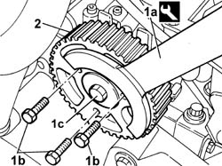
Op. 7055B54 UNDER-ENGINE GUARD - R R Op. 4450B04 RIGHT FRONT WHEEL R R Op. 1092G10 SINGLE ENGINE BELT R R See in Op. 1092A10 See in Op. 1032D12 See in Op. 1032B101. Using the tool (1a), undo the bolts fixing the timing drive pulley (1b) and loosen the bolt (1c) fixing the flywheel underneath.
Manual illustration 244000499DescriptionCodeFunction
1aCounter-torque1.860.776.000Timing pulley lock
2. Remove the toothed camshaft pulley
Manual illustration 244002480
Engines: 2.0 JTD 8V
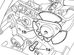
1. Undo the bolt (1a) loosened previously and remove the flywheel (1b).
Manual illustration 244002481
Engines: 2.0 JTD 8V
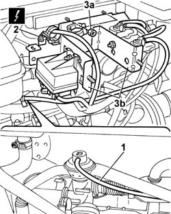
See in Op. 1048A21- Op. 1048B16 PIPES AND/OR ELBOW BETWEEN TURBOCHARGER AND THROTTLE CASING - R.R. See in Op. 1080C17-1. Disconnect the vacuum pipe from the EGR valve.
Manual illustration 244000463DescriptionConnector
2Heater plugs control unitM015C
2. Disconnect the electrical connection for the heater plugs control unit.
Manual illustration 244002482
Engines: 2.0 JTD 8V
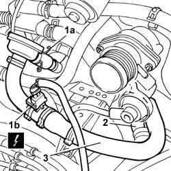
1. Press the retaining spring (1a) and disconnect the electrical connection (1b) for the engine oil vapour heating resistance.
Manual illustration 244000463DescriptionConnector
1bOil vapour heating resistanceO007A
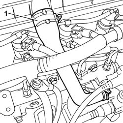
2. Disconnect the engine oil vapour pipe from the air intake pipe between the filter and the turbocharger.3. Remove the oil vapour pipe.
Manual illustration 244002483
Engines: 2.0 JTD 8V
- Disconnect the electrical connection for the timing sensor.
Manual illustration 244000463DescriptionConnector
.Timing sensorK047
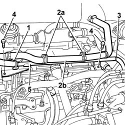
1. Disconnect the engine coolant reservoir recirculation pipe.2. Open the bands (2a) and release the heater water pipe (2b).3. Disconnect the flexible recirculation pipe from the thermostat.4. Undo the fixing bolts.5. Remove the rigid water recirculation pipe.
Manual illustration 244002484
Engines: 2.0 JTD 8V
1. Disconnect the engine oil vapour pipe from the separator.
Manual illustration 244002485
Engines: 2.0 JTD 8V
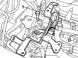
1. Undo the fixing bolts.2. Remove the bracket on the pressure pump mounting.
Manual illustration 244002486
Engines: 2.0 JTD 8V
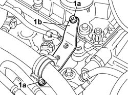
1. Undo the bolts (1a) and move the bracket (1b) from the housing.
Manual illustration 244002487
Engines: 2.0 JTD 8V
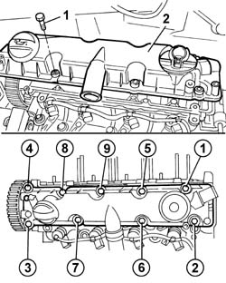
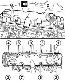
1. Undo the fixing bolts in the order given below.2. Remove the tappet cover.
Manual illustration 244002488
Engines: 2.0 JTD 8V
1. Undo the fixing bolts in the order given below.2. Remove the camshaft housing.
Manual illustration 244002489
Engines: 2.0 JTD 8V
1. Remove the camshaft (1a) complete with oil seal (1b).
Manual illustration 244002490
Engines: 2.0 JTD 8V

RefittingManual illustration 21

RemovingManual illustration 20
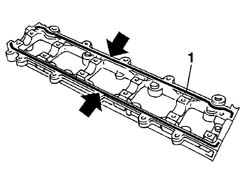
- Fit the camshaft in the housing in the cylinder head.1. Apply silicon sealant to the camshaft housing fitting surface.
Manual illustration 244000495DescriptionQty.ComponentTypeClassification
1DOW CORNING, 7091-CYLINDER HEAD EXTENSIONSilicone sealant-
Manual illustration 244002491
Engines: 2.0 JTD 8V
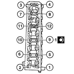
- Fit the camshaft housing.- Tighten the twelve bolts to the recommended torque following the order given.
Manual illustration 244000559Value - daNmFasteningComponentØ  
11,0BoltCYLINDER HEAD EXTENSION FASTENERS-
Manual illustration 244002492
Engines: 2.0 JTD 8V
- Fit the tappet cover in the housing on the cylinder head.1. Tighten the bolts fixing the tappet cover to torque in the order given.
Manual illustration 244000559Value - daNmFasteningComponentØ  
.1,0BoltCAM COVER-
Manual illustration 244002493
Engines: 2.0 JTD 8V
1. Fit the new oil seal (1b) on the camshaft using the tool (1a).
Manual illustration 244000499DescriptionCodeFunction
1aFitting tool1.860.990.000Camshaft front oil seal
Manual illustration 244002494
Engines: 2.0 JTD 8V
- Tighten the bolts fixing the thermostat side bracket.- Fit the bracket on the pressure pump mounting and tighten the fixing bolts.- Connect the engine oil vapour pipe to the separator.- Fit the rigid water recirculation pipe and tighten the fixing bolts.- Connect the flexible recirculation pipe to the thermostat.- Secure the heater water pipe to the bands on the rigid pipe.- Connect the engine coolant reservoir recirculation pipe.- Connect the electrical connection for the timing sensor.
Manual illustration 244000463DescriptionConnector
.Timing sensorK047
- Fit the oil vapour pipe.- Connect the engine oil vapour pipe to the air intake pipe between the filter and the turbocharger.- Connect the electrical connection for the engine oil vapour heating resistance.
Manual illustration 244000463DescriptionConnector
.Oil vapour heating resistanceO007A
- Fit the bracket, complete with solenoid valves and heater plugs control unit, and tighten the nuts fixing it to the bodyshell.- Connect the electrical connection for the heater plugs control unit.
Manual illustration 244000463DescriptionConnector
.Heater plugs control unitM015C
- Connect the vacuum pipe from the EGR valve.- Fit the power assisted steering fluid reservoir and tighten the fixing bolts to the crossmember. See in Op. 1080C17 See in Op. 1048A21 Op. 1048B16 PIPES AND/OR ELBOW BETWEEN TURBOCHARGER AND THROTTLE CASING - R.R.- Fit the flywheel on the camshaft and tighten the fixing bolt.- Fit the toothed timing drive pulley and screw in the fixing bolts without tightening them.- Using the tool, stop the rotation of the toothed timing drive pulley and tighten the flywheel fixing bolt to torque.
Manual illustration 244000499DescriptionCodeFunction
.Counter-torque1.860.776.000Timing pulley lock
Manual illustration 244000559Value - daNmFasteningComponentØ  
.4,3BoltTIMING PULLEY FLANGE-
See in Op. 1032B10 See in Op. 1032D12 See in Op. 1092A10 Op. 1092G10 SINGLE ENGINE BELT R R Op. 4450B04 RIGHT FRONT WHEEL R R Op. 7055B54 UNDER-ENGINE GUARD - R R- Remove the vehicle from the lift.
Engines: 2.0 16V, 2.0 JTD 8V, 2.3 JTD 16V, 2.8 JTD 8V

RemovingManual illustration 20

RefittingManual illustration 21
See in Op. 1016A10 See in Op. 1016A20 Op. 4450B04 RIGHT FRONT WHEEL R R Op. 7055B54 UNDER-ENGINE GUARD - R R Op. 7055B54 UNDER-ENGINE GUARD - R R Op. 1092D10 AIR CONDITIONER COMPRESSOR DRIVE BELT - R + R Op. 1092B51 ALTERNATO/WATER PUMP DRIVE BELT - R+R FOR VERSIONS WITH AIR CONDITIONER See in Op. 1092A12 See in Op. 1008B10 See in Op. 1032D12 See in Op. 1032B14 Op. 1032B61 TIMING BELT PULLEY - R R See in Op. 1036B361. Undo the fixing nuts (1a) and remove the camshaft caps (1b).3. Remove the camshaft.
Manual illustration 244002495
Engines: 2.0 16V, 2.0 JTD 8V, 2.3 JTD 16V, 2.8 JTD 8V

RefittingManual illustration 21

RemovingManual illustration 20
- Fit the camshaft in the cylinder head.- Tighten the bolts fixing the caps.- Tighten the nuts fixing the caps to torque.
Manual illustration 244000559Value - daNmFasteningComponentØ  
11,8NutCAMSHAFT CAPSM8
Manual illustration 244002496
Engines: 2.0 16V, 2.0 JTD 8V, 2.3 JTD 16V, 2.8 JTD 8V
See in Op. 1036B36 Op. 1032B61 TIMING BELT PULLEY - R R See in Op. 1032B14 See in Op. 1032D12 See in Op. 1008B10 See in Op. 1092A12 Op. 1092B51 ALTERNATO/WATER PUMP DRIVE BELT - R+R FOR VERSIONS WITH AIR CONDITIONER Op. 1092D10 AIR CONDITIONER COMPRESSOR DRIVE BELT - R + R Op. 7055B54 UNDER-ENGINE GUARD - R R Op. 7055B54 UNDER-ENGINE GUARD - R R Op. 4450B04 RIGHT FRONT WHEEL R R See in Op. 1016A20 See in Op. 1016A10